


Evolución de la fabricación de hierro en altos hornos
Evolución de la fabricación de hierro en altos hornos
El origen de la primera fundición de hierro está oculto en la historia no registrada de la civilización humana. La primera evidencia del uso de implementos de hierro en la antigüedad en realidad proviene de Egipto, donde se encontró una herramienta de hierro en una unión entre dos piedras en una pirámide. El origen de muchos implementos de hierro prehistóricos fue probablemente el hierro meteórico. El hierro meteórico contiene entre un 5 % y un 26 % de níquel (Ni), mientras que el hierro fundido contiene solo trazas de Ni y, por lo tanto, los artefactos de hierro hechos a partir de meteoritos se pueden diferenciar de los objetos de hierro fundido.
Hace más de 4000 años, la gente descubrió el hierro meteórico. Pero pasaron otros 2.000 años antes de que comenzara la producción de hierro a partir del mineral de hierro extraído. Los primeros hallazgos de hierro fundido en la India datan de 1800 a. C. (antes de la era común). Se dice que la fundición de hierro tuvo lugar entre los calibes de Armenia, súbditos del Imperio hitita, alrededor del año 1500 a. Cuando su imperio se derrumbó alrededor de 1200 a. C., las diversas tribus se llevaron consigo el conocimiento de la fabricación de hierro y lo extendieron por Europa y Asia. El conocimiento del trabajo del hierro en toda Europa y Asia occidental se remonta en última instancia a esta fuente. La Edad del Hierro comenzó con el descubrimiento de la fundición del hierro.
Inicio de la fundición de hierro
Al igual que con la reducción de minerales de sulfuro de cobre, la primera reducción de óxido de hierro probablemente fue accidental. Fueron los poderes de observación los que llevaron a estos antiguos metalúrgicos (que eran los mineros, químicos y tecnólogos de su época) a darse cuenta de que el hierro se podía producir en hornos simples mediante la reducción directa con carbono (C) del mineral de óxido. La primera representación registrada de un proceso de fundición se encontró en la pared de una tumba egipcia que data de alrededor del año 1500 a. (Fig. 1) Este proceso era un simple pozo con mineral y combustible desconocido que tenía el fuego intensificado mediante el uso de fuelles operados con el pie. Durante los siguientes 3000 años, las técnicas para la producción de hierro no cambiaron significativamente con la esponja de hierro producida por la reducción de C de los óxidos y los productos de hierro hechos al machacar la esponja.
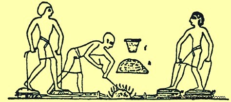
Fig. 1 Proceso de fundición de hierro representado en una tumba egipcia
Los minerales de óxido de hierro están presentes en muchas áreas del planeta tierra. Por lo tanto, aproximadamente al mismo tiempo que se llevaba a cabo la reducción de minerales de hierro en Egipto, también se estaba haciendo en otras áreas. India, China, África y Malaya sirvieron como sitios para este desarrollo inicial de las prácticas de fabricación de hierro. Quizás sea significativo que los hornos desarrollados en estos países fueran todos bastante similares. Había diferencias en forma y tamaño, pero los hornos eran funcionalmente idénticos. . La reducción química a hierro ocurrió sin fundir, y el metal resultante era relativamente puro y blando y se denominó hierro forjado. Se podía martillar en formas útiles. Se podían fabricar lanzas, puntas de flecha, dagas y otras herramientas y armas a partir de este material. hierro forjado.
Durante aproximadamente 2000 años, hasta aproximadamente el final del primer milenio EC (Era Común), el hierro se producía en pequeños hogares locales mediante el proceso de "floración". El tamaño de estas estructuras no está disponible en las investigaciones arqueológicas, pero una reconstrucción moderna de un horno bloomery tenía unas dimensiones internas de 300 mm de diámetro. x 1000 mm de alto. En el proceso de floración se construyó un hogar y en él se colocaron múltiples capas de carbón vegetal y mineral de hierro hasta que se produjo un montículo. Alrededor de este montículo se construyó una carcasa de arcilla y ladrillo dejando un orificio en la parte superior para los gases de escape y un orificio en la parte inferior para una ráfaga de aire producida por el funcionamiento de los fuelles. Luego se encendió el carbón y se hizo funcionar el fuelle hasta que se agotó el carbón. Luego se abrió la carcasa y, si el proceso había ido bien, entonces había una pila de hierro esponjoso y un charco de escoria. El hierro esponjoso caliente se golpeaba con un martillo para producir un tocho de hierro o productos de hierro. Las reacciones que tienen lugar durante la fundición en el proceso de floración se describen aquí. El fuego de carbón produjo monóxido de carbono (CO) y el calor extrajo agua del mineral del pantano para producir hematita. El CO redujo la hematita a óxido ferroso, wüstita. El CO luego reduce la wüstita a hierro elemental. La reacción no llegó hasta el final; procedió a una posición de equilibrio y así el gas resultante fue una mezcla de CO y dióxido de carbono (CO2). Sin embargo, la wüstita también podría reaccionar con cualquier arena para producir olivino de hierro (fayalita), que es el principal componente de la escoria producida. Esta fayalita era un callejón sin salida en lo que respecta al proceso de fundición porque no podía reducirse a hierro elemental en las condiciones del horno. El hierro producido tenía un punto de fusión de aprox. 1.540 ºC, mientras que el punto de fusión de la escoria fue de alrededor de 1.100 ºC. Las temperaturas alcanzadas fueron lo suficientemente altas como para derretir la escoria, pero no tanto como para derretir el hierro. El proceso funcionó bastante bien, aunque la escoria restante aún contenía mucho hierro, a menudo hasta un 60 % o más de FeO (óxido ferroso). La escoria era de dos variedades, siendo en parte de la naturaleza porosa abierta de la escoria de mineral de pantano, y en parte compacta, dura y muy infusible, como se obtiene del mineral de hierro rojo.
Desarrollos en el proceso de fabricación de hierro
Las mejoras en este primer proceso de fabricación del hierro se realizaron recubriendo el pozo de fundición con piedras y barro y utilizando fuelles de madera y cuero (Fig. 2). En China, el uso del hierro apareció alrededor del 600 a. C. y se extendió ampliamente durante el período 403 a. C. a 222 a. C. Los chinos desarrollaron una tecnología superior de fabricación de hierro y el hierro líquido se produjo ya en el año 200 a. C. basándose en el descubrimiento de utensilios de hierro fundido. Los escritos antiguos tanto en China como en India se refieren a la fundición de hierro. Otros artefactos incluyen espadas, hachas, hoces y azadones. Hacia el año 310 d. C. se podía producir una cantidad suficiente de hierro para permitir la construcción de los famosos pilares de hierro de Delhi y Dhar en la India. El pilar de hierro forjado de Delhi tiene 18 m de altura, 410 mm de diámetro y pesa 17 toneladas. En Japón, el proceso tradicional de fabricación de hierro y acero conocido como 'Tatara' no se desarrolló por completo hasta el siglo XVII EC. En América del Norte, América del Sur y Australia, los antiguos habitantes no conocían la fundición de hierro. Los europeos trajeron la tecnología de fabricación de hierro a estos países.
El proceso de fabricación de hierro desarrollado alrededor del mar Mediterráneo se había extendido hacia el norte a través de Europa. Los fenicios, celtas y romanos ayudaron a difundir la tecnología de fabricación de hierro. Una de las técnicas de fabricación de hierro difundidas por los romanos hasta el norte de Gran Bretaña fue el antiguo horno de cuenco o de cuba. Este horno consistía en un recipiente en forma de cuenco o un pozo cilíndrico de 2 m de altura que se construía en la ladera de una colina. El aire que se usaba para avivar el fuego dentro del horno lo proporcionaba una abertura construida cerca del fondo del recipiente que miraba hacia el viento predominante. El horno se llenaba a través de la abertura superior con capas de carbón y mineral de hierro que se encendían a través de la abertura inferior.
Hay dos teorías sobre cómo se condujo la fundición de hierro, una que el viento entró a través de la abertura inferior proporcionando aire que calentó el proceso y la otra que el viento sopló sobre la parte superior abierta, creando un área de baja presión a lo largo de la pared frontal interior. que aspiraba aire a través de la abertura inferior (Fig. 2). En ambos casos, el proceso dependía del viento y no era fiable durante todo el año. El producto era una vez más una masa de esponja de hierro, que se extraía a través de la abertura inferior y luego se martillaba hasta darle su forma final.
Otro tipo de fundición de hierro temprana fue el horno de colmena (Fig. 2). Este horno se construyó sobre un terreno llano apilando capas alternas de carbón vegetal y mineral de hierro. El montículo se cubrió con una gruesa capa de arcilla y se insertaron cerbatanas conectadas a fuelles a través de las paredes laterales inferiores. La capa inferior de carbón se encendía y los fuelles proporcionaban aire a presión. Al final de este lote tipo fundido, el domo de arcilla se derrumbó. El hierro esponja producido se extrajo del horno de colmena demolido para martillarlo. La producción en estos hornos consistía en pequeños trozos de hierro y el horno de fundición tenía que ser demolido y reconstruido después de cada ciclo de producción.
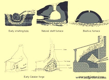
Fig. 2 Primeros procesos de fabricación de hierro
Estos tipos de procesos de fabricación de hierro se utilizaron durante varios cientos de años hasta la era moderna sin muchas mejoras. Luego, aproximadamente durante el siglo VIII, una pequeña fragua que operaba en las montañas de Cataluña, en el noreste de España, representó uno de los primeros avances metalúrgicos significativos en la fabricación de hierro. La fragua catalana primitiva (Fig. 2) tenía una copa de piedra llamada solera, de unos 910 mm de alto y 760 mm de diámetro. A poca distancia por encima del frente de la base había una pequeña abertura que permitía instalar una boquilla conocida como tobera. La tobera de la tobera estaba conectada al fuelle para el suministro de aire. El hogar estaba lleno hasta el nivel de la tobera con trozos de carbón. Luego, se colocó mineral de hierro sobre la tobera y se colocó más carbón en capas sobre el mineral. Se encendía el carbón y el aire de los fuelles forzaba el CO2 caliente sobre el mineral, lo que reducía el mineral de hierro a una masa de hierro caliente y grumosa. La masa de hierro conocida como flor podía pesar hasta 160 kg y podía sacarse del hogar de la fragua con unas tenazas sin destruir la estructura de piedra. Esta cantidad de hierro se podía generar en 5 horas mientras que las tecnologías anteriores solo podían producir unos 23 kg en 5 horas. La fragua catalana fue aumentando de tamaño durante los siguientes 200 años y su uso se extendió a Francia, Bélgica, Inglaterra y Alemania. Los tamaños del hogar aumentaron a 1 m cuadrado y se construyeron con bloques de piedra rectangulares. La cantidad de aire suministrado a través de la tobera también se incrementó mediante el uso de un aspirador de aire conocido como "trompe". A medida que el agua cae a través de la columna trampantojo, el aire ingresa al tubo y luego se expulsa por el fondo de la caja. Cuando este dispositivo se incorporó a la fragua catalana, la presión de la explosión a través de la tobera era de 0,10 a 0,14 kg/cm2, que era significativamente más de lo que podía producir un fuelle de mano o pie. Esta presión de explosión adicional aceleró el proceso de fundición y aumentó la producción.
Desde el siglo X hasta el siglo XIV, la fragua catalana experimentó una mayor evolución. Los fuelles operados a mano o con el pie fueron reemplazados por fuelles operados por ruedas hidráulicas y esto aumentó el volumen y la presión del chorro de aire. Luego, hubo intentos de capturar el calor residual de la pila de la fragua aumentando la altura de la pila y cargando mineral de hierro y carbón desde la parte superior de la pila para que el mineral pudiera precalentarse. Estos hornos tenían una pila de mampostería de piedra de 1,8 m a 4,8 m de altura. Las alturas de las pilas y, debido a ello, las alturas de la carga de materia prima podrían aumentar debido a la mayor presión de la explosión que podría ser empujada hacia arriba por estas pilas desde los fuelles accionados por ruedas hidráulicas.
El horno Stuckofen (Fig. 3), que era el más alto, no solo tenía una chimenea de 4,8 m de altura, sino también un cambio en la geometría de la chimenea. El horno tomó la forma de dos conos truncados conectados en el diámetro más ancho. Dos toberas se convirtieron en el estándar ya que la rueda hidráulica impulsaba dos fuelles y uno de ellos se comprimía constantemente para generar la explosión. Había una abertura en la parte inferior del horno para sacar la escoria, pero hubo que quitar la piedra para extraer el producto final, que seguía siendo una protuberancia de hierro que pesaba alrededor de 318 kg. El horno Stuckofen podía producir de 100 a 150 toneladas en un año, lo que superaba la capacidad de producción de una fragua catalana. Un subproducto de este horno fue el hierro líquido. Debido a que el mineral de hierro tenía un tiempo de residencia más largo en el horno para sufrir reacciones químicas y estar expuesto a temperaturas más altas, el hierro podía absorber más C, lo que reducía el punto de fusión. Cuando se quitó la flor del horno, también se eliminó este hierro líquido. Al principio se consideró un detrimento ya que era demasiado frágil para ser trabajado con el martillo. En algunos casos, se recargó en el horno o incluso se tiró como desecho. El horno Stuckofen se considera el precursor del alto horno moderno (BF). Se modificó aún más en el 'Blauofen' (horno de soplado) que era capaz de producir hierro líquido o hierro esponja de grado de forja a discreción de los fabricantes de hierro. Este cambio en los productos deseados se logró modificando la cantidad de combustible cargada entre un 10 % y un 15 % y bajando la posición de las toberas en 500 mm y empujándolas más adentro del horno. En el siglo XVI estos hornos tenían 6,7 m de altura y podían producir alrededor de 1,8 toneladas de hierro por día con una tasa de combustible de alrededor de 250 kg de carbón vegetal por cada 100 kg de hierro producido. Estos hornos tenían una esperanza de vida de unos 45 días.
El siguiente paso en el diseño de hornos para producir hierro líquido todo el tiempo fue el 'Flussofen' (horno de flujo). El desarrollo del Flussofen o primer BF fue en el siglo XIV en el valle del río Rin y áreas adyacentes de Francia, Bélgica y Alemania. Sin embargo, con un cambio en la tecnología de la guerra, así como en la fabricación de hierro, la fundición de cañones de hierro fundido se convirtió en la industria dominante en lugar de la forja de espadas de hierro esponja. Ya en 1300 EC, los fabricantes de hierro buscaron activamente producir hierro líquido para fundir armas. La primera documentación confiable de un BF conocido data de 1340 EC cuando se construyó el horno en Marche Les Dames, en Bélgica. La propagación del Flussofen o BF fue relativamente lenta. Las naciones continentales de Europa tienen derecho al mérito de haber desarrollado íntegramente el BF a partir del método primitivo de producción de florones de hierro en una fragua catalana. El BF moderno es un horno de cuba que evolucionó gradualmente a partir de Stuckofen y Flussofen.
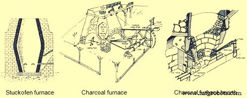
Fig. 3 Horno Stuckofen y horno de carbón
Evolución del alto horno de carbón vegetal
Los BF de carbón vegetal (Fig. 3) desarrollados en Europa continental pronto se extendieron a Gran Bretaña, donde se produjo la siguiente evolución en la tecnología de fabricación de hierro. Un BF construido en Monmouthshire, Inglaterra en 1565 CE fue el primer horno construido en el bosque de Dean, que se convirtió en un importante centro de fabricación de hierro. Este BF tenía 4,6 m de altura y 1,8 m en el bosh, el punto más ancho dentro del horno donde se unían los dos conos truncados. Para 1615 CE había 300 BF con un promedio de alrededor de 2 toneladas por día por horno. La tasa de crecimiento fue tan rápida que provocó la deforestación total de la tierra para la producción de carbón vegetal. Durante la década de 1600, se impusieron restricciones legales para proteger los bosques restantes y se cerraron muchos BF.
El primer BF construido en América del Norte fue en Falling Creek, Virginia en 1622. Este horno nunca se puso en funcionamiento ya que todos los trabajadores de la planta murieron y los nativos americanos destruyeron la ferretería. El primer BF de carbón exitoso en América del Norte fue en Saugus, Massachusetts, a partir de 1645. Este BF tenía una pila de 6,4 m de altura con las paredes exteriores inclinadas hacia adentro a medida que se elevaban y 7,9 m cuadrados en la base. El horno estaba hecho de granito y otras piedras locales unidas con un mortero de arcilla. Descansaba sobre un terreno llano en el que se había excavado un sistema de drenaje subterráneo para protegerlo de la humedad a la que el agua que impulsaba su gran rueda de fuelle lo hacía especialmente susceptible. El BF tenía una pila con un interior más o menos en forma de huevo y con un diámetro máximo conocido como la parte superior del bosh de 1,8 m. El bosh, que desciende, soportaba la carga de mineral, fundente y carbón. Un crisol cuadrado llamado hogar estaba debajo del fondo del bosh y estaba revestido con piedra arenisca (Fig. 3). Había una pared interior con arena, arcilla y escombros entre el revestimiento interior y la mampostería exterior que actuaba como amortiguador para la expansión y contracción durante los ciclos de calefacción y refrigeración. Había arcos grandes y profundos en dos de las paredes exteriores. A través del arco más pequeño pasaron las narices de los dos fuelles de 5,5 m y las dos toberas, que descargaron la ráfaga en el BF. Debajo del arco más grande estaba el área de trabajo del hogar y el piso de fundición. El crisol o hogar actuaba como depósito del hierro líquido. El hogar tenía 460 mm cuadrados en la base, pero se amplió a 530 mm cuando alcanzó su altura máxima de 1,1 m. Un saliente de su parte inferior, llamado ante-hogar, constaba de dos muros y una piedra de bosque o presa. Arriba, y apartado de la presa, había un muro cortina de piedra, llamado 'tymp', cuyo borde inferior descendía más bajo que la parte superior de la presa. A través de la abertura entre el tímpano y la presa, un operador sacaba el hierro para la fundición del molde y con una barra de hierro, llamada campanero, extraía la escoria que se pegaba a las paredes o se acumulaba alrededor de la punta de la tobera. Para la protección contra el desgaste de tales operaciones, tanto el tímpano como el dique estaban revestidos con placas de hierro. La remoción de escoria se logró rastrillando el material líquido sobre la piedra de la presa en un lugar llamado muesca de ceniza. Sin embargo, para perforar el hierro, se requería romper un tapón de arcilla insertado en un espacio estrecho, llamado orificio para el grifo, entre una de las paredes laterales del frente del hogar y un extremo de la presa.
Además de este complicado trabajo de albañilería, la construcción del BF implicó trabajos en madera y en cuero. Entre la parte superior de BF y el acantilado adyacente corría una estructura de madera pesada llamada puente de carga. Las materias primas se sacaron en carretillas de sus reservas en el acantilado, a través del puente de carga hasta la parte superior del BF. En tres lados de la parte superior del BF había pantallas de viento de madera, instaladas para proporcionar un refugio seguro para los operadores que cargaban materias primas en el orificio de carga que emitía humo, chispas y ocasionalmente llamas. La chimenea BF a nivel del suelo estaba envuelta en dos lados por una estructura de madera adosada llamada casa de fundición. Esta estructura proporcionó cobertura para el área de fundición de zanjas y moldes, así como para los fuelles. Los dos fuelles eran accionados de manera recíproca por un árbol de levas conectado a una rueda hidráulica de sobreimpulso. Los fuelles se desinflaban con las levas del eje principal y se inflaban con contrapesos que consistían en cajas de madera llenas de piedras y montadas en las vigas móviles que se extendían más allá del techo de la casa de fundición a través de orificios cortados para acomodarlos. El BF consumió 3 toneladas de mineral de hierro, 2 toneladas de fundente y 2,6 toneladas de carbón vegetal por tonelada de hierro producido. El orificio del grifo se abrió dos veces al día y se extrajeron alrededor de 450 kg de hierro líquido durante cada colada. El hierro líquido se extraía en una sola zanja o se vertía en moldes de arena para producir productos domésticos como ollas, sartenes, placas de cocina, etc.
La fabricación de hierro al carbón descrita anteriormente cambió solo ligeramente durante los siguientes 100 años hasta el siglo XVIII. Las pilas BF aumentaron de tamaño y se realizaron mejoras en los equipos de soplado. Un BF típico de carbón de la década de 1700 tenía un tamaño aumentado de 9,1 m de altura y un diámetro de 2,4 m. El aumento en el tamaño de BF fue posible solo a través de mejoras en el equipo de suministro de viento que resultó en presiones de explosión más altas. La primera mejora en los sistemas de voladura fue la invención de las tinas de soplado de madera que eran cuadradas o redondas y eran similares a barriles de madera unidos con aros de acero externos. Una manivela excéntrica en la rueda hidráulica tenía un vástago de pistón alternativo y una cuba de soplado a cada lado. El pistón dentro de la tina estaba cubierto de cuero para formar un sello. Mientras un pistón ascendía para comprimir aire en una tina, el otro pistón descendía en la otra tina. En la parte superior de cada tina había un tubo de salida conectado a una caja mezcladora común que siempre estaba bajo presión. La caja de mezcla alimentaba aire comprimido a un conducto de aire o tubería principal que conducía a las toberas del horno. Una cuba de soplado típica tenía 1,8 m de diámetro y 1,8 m de altura, y producía 0,14 kg/cm2 de presión de explosión. El concepto de tinas de soplado de madera fue llevado un paso más allá en 1760 por John Smeaton de Inglaterra. Convirtió las tinas de madera en tinas de hierro fundido impulsadas primero por una rueda hidráulica y luego en 1769 por una máquina de vapor. El primer BF que utilizó motores de soplado accionados por vapor se construyó en Escocia en 1769. La invención de los motores de soplado accionados por vapor dio como resultado presiones de explosión más altas que permitieron un mayor uso de combustibles minerales (coque y carbón). Estas mejoras de 1700 llevaron a que la producción de BF aumentara de 3 a 5 toneladas por día a fines de 1700 desde una tonelada por día de 1600 BF. Esto, junto con el uso de combustibles minerales, provocó una rápida disminución en la cantidad de hornos de carbón en Europa, aunque la capacidad de hierro con carbón aumentó en América del Norte a medida que las poblaciones se mudaron al oeste, donde había una gran disponibilidad de madera.
En la década de 1800, la producción de carbón de hierro alcanzó su punto máximo y luego disminuyó. A mediados de la década de 1800, se descubrieron minerales de hierro de alta calidad en Pensilvania y la península superior de Michigan, que tenían densos bosques vírgenes. Los BF de carbón construidos en esta zona fueron los más grandes y mejor equipados. Estos BF tenían alturas de chimenea de 13,7 m y diámetros de bosh de 2,9 m. El número de toberas aumentó de dos a tres, una en cada uno de los tres lados del horno, mientras que el orificio del grifo estaba en el cuarto lado. El equipo de soplado solía ser cilindros de soplado horizontales con diámetros típicos de hasta 1270 mm y carreras de 1,5 m. Los montacargas de plataforma tipo elevador reemplazaron los puentes de carga y todos los minerales de hierro y fundentes se pesaron como parte de una carga estándar. El carbón todavía se cobraba por el volumen de una carretilla grande. Las placas de concha de hierro reemplazaron lentamente las pilas de piedra de mampostería y los revestimientos de piedra natural se actualizaron con ladrillos de alúmina.
Una de las principales mejoras tecnológicas instaladas en estos hornos de carbón vegetal fue el equipo de carga. Originalmente, las materias primas se vertían en una pila de boca abierta a través de la cabeza del túnel. Los operadores de BF se dieron cuenta de que un horno de techo abierto tenía dos desventajas:primero, el gas inflamable que salía de la chimenea no podía capturarse para encender las calderas y, segundo, la distribución de materias primas estaba causando ineficiencias en el funcionamiento del horno. Los primeros esfuerzos en 1832 en Alemania para capturar el gas dieron como resultado la instalación de una tapa con bisagras sobre el orificio de carga que solo se abría cuando las materias primas se descargaban de las carretillas (Fig. 4). También se colocó una abertura en el costado del horno ubicado en la chimenea superior. Esta abertura estaba equipada con una tubería conocida como bajante que llevaba el gas BF al nivel del suelo para quemarlo en equipos auxiliares.
El problema de la ineficiencia del BF debido al cobro de materias primas necesitaba una solución más complicada que evolucionó en varios pasos. La causa de esta ineficiencia, descrita por las altas tasas de combustible, se debió a que el material fino que se descargó a través del orificio de carga en el centro del BF permaneció en el centro del montón mientras que las partículas gruesas rodaron hacia la pared del horno. Esto dio como resultado una mayor permeabilidad en la periferia de BF y, por lo tanto, la mayoría del gas y el calor ascendieron por las paredes. Esto fue perjudicial para la operación de BF ya que el material en el centro del BF llegó al área del bosh sin estar preparado para derretirse y, al mismo tiempo, el flujo excesivo de gas en la pared aumentó el desgaste del revestimiento. El primer intento de resolver este problema de distribución de la carga fue la introducción de un aparato de carga de "copa y cono" (Fig. 4). Consistía en un embudo de hierro fundido cónico invertido fijado a la parte superior del horno que alimentaba el orificio de carga. Este cono tenía alrededor del 50 % del diámetro de la garganta. Dentro del cono había una copa de hierro fundido, que estaba suspendida en una viga de apoyo frente a un contrapeso. La copa se levantó manualmente mediante un cabrestante conectado al contrapeso. Este aparato logró capturar el gas, pero aun así una gran cantidad de material grueso rodó hacia la pared. La siguiente modificación al equipo de copa y cono fue colgar un cono truncado de hierro fundido dentro del horno (Fig. 4). Esto resultó en mover el pico de materias primas más cerca de la pared para que las partículas gruesas ahora también pudieran rodar hacia el centro del horno, lo que resultó en una mejor permeabilidad central y flujo de gas.
El siguiente paso evolutivo en la carga que eliminó por completo la copa y el cono fue colgar un cono invertido que se abría hacia abajo en el horno (Fig. 4). Este fue el primer top BF tipo campana. Esta campana logró empujar el pico de la pared, lo que redujo el flujo de gas alrededor de la periferia y aumentó el flujo de gas en el centro, pero el gas BF escapaba de la chimenea con cada descenso de la campana. La solución a esto fue tener una campana y una tapa para el orificio de carga. Cuando se descargó el material de la carretilla, la tapa estaba levantada pero la campana estaba cerrada manteniendo el gas en el BF. Luego se cerró la tapa y se descargó la campana, que también mantuvo el gas en el BF y al mismo tiempo produjo la distribución adecuada de la carga. Los resultados de estas mejoras fueron una mejor eficiencia de las reacciones físicas y químicas dentro del BF, lo que redujo los requisitos de combustible, aumentó la productividad y disminuyó el desgaste del revestimiento refractario.
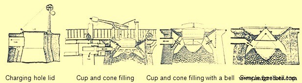
Fig. 4 Evolución de los mejores equipos de BF
A medida que aumentaba la producción de BF debido a muchas mejoras de diseño, la eliminación de productos líquidos (hierro y escoria) se convirtió en un problema. La producción de carbón vegetal BF había aumentado durante el período de una tonelada a 25 toneladas por día. Este tonelaje más alto no se podía manejar con dos lanzamientos por día a través de una sola zanja frente al orificio del grifo. El tamaño del edificio de la casa de yeso aumentó a alrededor de 12 m de ancho y 21 m de largo. La fundición contenía áreas separadas para la fundición de hierro y la eliminación de escoria. El costado para la remoción de hierro consistía en una zanja grande llamada canal que se inclinaba hacia abajo desde el frente del horno hacia el piso de la casa de fundición lleno de arena. Luego se derramó en dos sistemas de corredores. Un corredor principal en cada sistema corría paralelo a la longitud de la casa de colada. A medida que este corredor se inclinaba cuesta abajo, se hicieron una serie de diques a intervalos regulares. En ángulo recto, antes de cada presa, se formaba en la arena un corredor más pequeño llamado "cerda". Luego, de esta cerda había numerosas cavidades llamadas "cerdos". Estos nombres se aplicaron porque este sistema parecía una línea de lechones amamantando a su madre (Fig. 5). Había varias filas paralelas de cerdas y cerdos producidos al empujar formas de madera en forma de D en la arena húmeda del piso del galpón. Durante el lanzamiento, a medida que cada cerda y sus cerdos se llenaban con hierro líquido, el dique de arena en el corredor principal se rompía con una barra y el metal fundido corría cuesta abajo hacia la próxima cama de cerdas y cerdos. Había dos sistemas completos que permitían lanzar el BF con más frecuencia. Como un lado se llenó con hierro líquido, al otro lado se le quitaron los cerdos y se reformaron las camas.
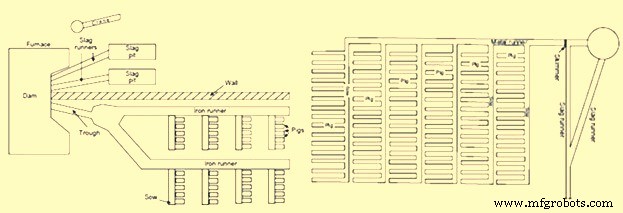
Fig. 5 lechos de cerdos en casa de yeso
El otro lado de la fundición se utilizó para la eliminación de escoria. La escoria corría constantemente sobre el frente de la presa, bajaba por un corredor de escoria y entraba en un pozo de escoria. El dique de escoria en la parte delantera del BF se dividió en dos mitades y cada mitad alimentaba un conducto de escoria y un pozo de escoria separados. El pozo de escoria era una gran depresión en la arena con crestas en el fondo. Estas crestas actuaron como puntos de fractura cuando llegó el momento de eliminar la escoria solidificada. En algunas fundiciones, se utilizaba una grúa de madera tipo pluma para levantar grandes piezas de escoria. Si el operador de la fundición notaba que la capa de escoria se volvía demasiado gruesa, generalmente colocaba una barra en el centro de la escoria líquida. Luego, cuando la escoria se enfriaba alrededor de la barra, se podía enrollar una cuerda o una cadena alrededor y la grúa levantaba los grandes trozos de escoria. Para la eliminación de escorias, también se disponía de dos sistemas completos de escoria, de modo que mientras se utilizaba uno, se limpiaba y preparaba el otro.
Se entiende que el origen de la palabra 'fundición' proviene de la percepción de que el hierro líquido se 'arrojó' fuera del horno. La operación de fundición constaba de dos partes. En la primera parte, mientras se formaba escoria líquida en el BF, flotaba sobre el hierro líquido hasta alcanzar un nivel lo suficientemente alto como para fluir entre el tymp y la presa hacia el canal de escoria y el pozo. La segunda parte de la fundición fue la extracción del hierro líquido de la solera del horno. Esto comenzó apagando la explosión y luego clavando una barra puntiaguda en el orificio del grifo con un mazo. El hierro líquido fluyó por el canal hacia cada cerda consecutiva y sus cerdos. Cuando el hierro líquido dejó de fluir, el orificio del grifo se tapó manualmente con una mezcla húmeda de arena y arcilla refractaria o arena y carbón. Luego, la ráfaga se devolvió al horno.
Después de la colada, los operadores de la casa de colada retiraron el hierro solidificado de las camas de los cerdos. Cuando los cerdos estaban lo suficientemente fríos para manipularlos, se enviaban para su despacho. Este ciclo se repetía seis veces al día, produciéndose de 4 a 6 toneladas en cada colada. El arrabio producido se clasificó en diferentes grados. El carbón de hierro tenía un valor de azufre bajo, lo que dio como resultado un hierro fundido gris resistente que se utilizó para producir rieles y ruedas de vagones necesarios para sostener las vías férreas en expansión del siglo XIX.
Los BF de carbón se descontinuaron a fines del siglo XIX, ya que sus costos de producción ya no podían hacer frente a la competencia proveniente de las prácticas de fabricación de hierro a base de minerales.
Fabricación de hierro a base de combustibles minerales
Debido al agotamiento de los bosques vírgenes necesarios para sustentar la producción de hierro con carbón vegetal, se hizo necesario buscar fuentes alternativas de combustible. Este combustible alternativo llegó en forma de carbón bituminoso, carbón antracita, coque e incluso turba. El desarrollo de la fabricación de coque y hierro antracita fue paralelo y coexistió con la producción de carbón vegetal durante los siglos XVIII y XIX. El uso de carbón bituminoso y turba fue limitado y nunca se convirtió en un combustible importante para la fabricación de hierro. El uso de combustible mineral para la fabricación de hierro se inició en Gran Bretaña, ya que allí se produjo por primera vez la deforestación debida a la producción de carbón vegetal.
En 1708, Abraham Darby arrendó un pequeño BF de carbón en Shropshire y en 1709 ya producía coque. De 1709 a 1718, el coque se mezclaba con carbón vegetal en proporciones crecientes en este horno y en 1718 la BF utilizaba coque al 100 %. Hasta 1750, los tres BF que usaban coca regularmente pertenecían a la familia Darby. El uso de coque se extendió durante el período 1750 a 1771, con un total de 27 BF utilizando coque para la producción de hierro. The use of coke increased the production of iron since it was stronger than charcoal. It could support the weight of more raw materials and thus the size of BF could be increased. Coke also improved permeability in the BF, allowing a larger volume of wind to pass through the furnace. This larger volume of compressed air was provided by the steam engine and blowing cylinders.
The use of coke in continental Europe spread slowly. Coke was used in Le Creussot, France in 1785, Gewitz, Silesia in 1796, Seraing, Belgium in 1826, Mulheim, Germany in 1849, Donete, Russia in 1871 and Bilbao, Spain in 1880. In North America, the first use of 100 % coke as the fuel was in 1835 at Huntington, Pennsylvania. However, since 1797, coke was mixed with other fuels in BFs of US.
The efficient use of coke and anthracite in producing iron was accelerated not only by the use of steam-driven blowing equipment but also by the invention of preheating of the air being blown in the BF. In the beginning of the 19th century, it was believed that use of cold blast improved both the quantity and quality of pig iron since it was observed that the production of the BFs was more in winter months and it was erroneously concluded that the lower blast temperature was the reason. But the BF performance improved during the winter months due to the fact that the air was having lower humidity so that more combustion of fuel was supported by a given volume of air blown into the furnace.
In 1828, James Neilson patented his invention of supplying preheated air blast to the tuyeres. The heating equipment was a simple wrought iron box having dimensions 1.2 m x 0.9 m x 0.6 m. This wrought iron box was externally heated. The maximum blast temperature which could be attained with this box was 93 deg C and one box was needed for each tuyere. In 1832, Neilson improved his invention by constructing a larger oven by joined flanges, formed a continuous length of 30 m and provided a heating surface of 22.3 sq m. This oven, which was fired with solid fuel, produced a hot blast temperature of 140 deg C. Since this invention, continuous modification and improvement in the hot blast ovens were made and by 1831, Dixon developed a taller oven with U-shaped pipes that supplied hot blast at 315 deg C. By 1840, about 55 % of pig iron at Great Britain was produced with hot blast.
With the increase in the hot blast temperature, there was decrease in the quantity of fuel needed and increase in the BF production. However the hot blast equipment needed a lot of maintenance. The cast iron pipes supported within a brick oven had different expansion characteristics, which resulted in several cracked pipes. Another issue was that the delivery equipment used for the cold blast, which consisted of solid tuyeres and flexible leather joints between pipes, could not withstand the high temperatures. Another issue with the original hot blast systems was the increased cost of solid fuel to heat the ovens. These issues helped further improvements in hot blast equipment. First, solid fuel used for heating was replaced with BF gas. Initially primitive heat exchanger type hot blast equipment was built on top of the BF and simply used the waste heat to preheat the cold blast running through the cast iron pipes. Then the BF gas from the furnace top was conveyed to the hot blast oven where it was burned to generate heat. This type of hot blast oven became quite complex with numerous rows of vertical pipes. The issue of cracking of the cast iron pipes was tackled by eliminating the pipes and using refractory. For using this method, 2 to 4 stoves were installed for each BF. As one stove was being heated by the burning the BF gas, another was being drained of its heat by heating of the cold blast. In 1854, the Cambria Iron Works was the first plant in the US to use regenerative stoves. The stoves were constructed of iron shells, internally lined with refractory and containing refractories with multiple passages for the blast. A typical stove of this design had 186 to 232 sq m of heating surface. These stoves were representative of those produced by Cowper and Whitwell in 1857. The Whitwell stoves erected in 1875 were 6.7 m in diameter, 9.1 m high and had a total heat surface of 8546 sq m. These were the first stoves to use hexagonal refractory checkers, cast iron checker supports, and a semi elliptical combustion chamber to improve distribution of gas through the checkers. These stoves could supply hot blast to the BF with temperatures of 454 deg C to 566 deg C. This stove design has remained basically the same till date with minor modifications in refractory type, checker shape and stove size.
The other improvement in equipment required by the use of hot blast was the design of the tuyeres and the tuyere stock. The solid cast iron or cast copper tuyeres used on cold blast furnaces were replaced by water cooled tuyeres which were hollow, conical shaped castings which had water circulating through their interior. The pipes from the blowing engines to the tuyeres, which were jointed with leather on cold blast furnaces, were redesigned with metal-to-metal seats. As hot blast temperatures increased the inside of these blast mains and tuyere stocks were lined with refractory, which required an overall increase in size.
The use of hot blast was applied to both coke and anthracite furnaces. As blast pressure increased with new blowing engines, it was found that anthracite could be charged with charcoal to improve the BF productivity. During 1986 the first attempt was made to use anthracite in a cold blast furnace in eastern France. This attempt failed since the ignited anthracite broke up into small pieces and blocked the blast from entering the BF. The evolution of coke iron making and anthracite iron making paralleled each other in the US during the 1800s. In 1826, a small BF was erected in Pennsylvania to operate exclusively on anthracite coal. This practice was unsuccessful both there as well as at other places in the US. During 1833, Dr. Frederick Geissenhainer successfully used hot blast in experiments to smelt iron with anthracite coal. In 1836 the Valley furnace in Pennsylvania used 100 % anthracite and in 1837, George Crane produced 36 tons of anthracite iron per week from one of his BFs at South Wales. David Thomas was the most successful iron maker in using the anthracite in the BF. In 1838 he came to the US and built the Catasauqua BF in 1840 (Fig 6). The furnace was 10.7 m square at the base with 3.6 m bosh and a height of 13.7 m. The hot blast stoves, fired with coal, were capable of heating the blast to 315 deg C. Since this BF successfully produced 50 tons of good foundry iron per week, the furnace was used as a model for the construction of blast furnaces built for using anthracite as a fuel. By 1856 there were 121 anthracite furnaces in operation in the US.
Other fuels were also tried for iron making in the BF. These were peat and bituminous coal. Peat BFs were similar to charcoal furnaces and typically were no higher than 6.7 m. Because the peat was physically weak, the use of these furnaces was located near to the peat deposits and they never played a major role in iron making evolution. Bituminous coal had been used to supplement charcoal prior to the introduction of hot blast. In the 1830s, splint coal was used in Scottish hot blast furnaces. In 1856, there were 6 BFs in Pennsylvania and 13 BFs in Ohio using bituminous coal. The bituminous coal era of iron making was essentially finished by 1895. This method of iron making never became a major force since the coal broke up into small pieces as the BFs were made larger and used higher blast pressure. With coke being the strongest and most available fuel, the evolution of 100 % coke furnaces continued. However there were initial setbacks probably due to low strength coke. By the 1840s coke quality had improved through the use of beehive ovens. In 1867, the ‘Monster’ blast furnace was built at Norton, England. This coke furnace was 25.9 m high, 7.6 m across the bosh and had a working volume of 735 cum. An example of a large coke furnace in the US in 1884 was the Etna furnace located near Pittsburgh. This furnace was 21.3 m high, 6.1 m in diameter at the bosh, 3.4 m in diameter at the hearth and had seven 7 inch (178 mm) tuyeres, three Whitwell stoves and three blowing cylinders that were 2.1 m in diameter. This BF produced 115 tons/day in 1881, 161 tons/day in 1882 and 182 tons/day in 1883. The coke furnace design at this time was very similar to the anthracite furnaces of the same era (Fig 6).
Further evolution of coke blast furnace
The evolution of BFs using 100 % coke continued with major improvements being made between 1872 and 1913. Several technological improvements were made which were centered on the hard-driving BF practice of using more powerful blowing engines, higher blast temperatures, bigger furnaces, better charging equipment, improved raw material preparation and production of clean BF gas.
Blowing equipment design and capacity was a major step to higher production in the hard-driving BFs. Blowing cylinders were replaced with large steam reciprocating blowing engines capable of providing a greater volume of blast air at a significantly higher blast pressure. These blowing engines were of the walking beam, steam condensing type. The steam cylinder’s piston rod was connected to a gallows beam and then by a crank to a heavy, large diameter flywheel. The blowing cylinder’s piston rod was connected to the other end of the gallows beam and each stroke of the steam cylinder provided a corresponding stroke of the blowing cylinder. Cold blast pipes were fitted to each end of the vertically positioned blowing cylinder so that air was compressed on both directions of the stroke. The flywheel provided momentum for the return stroke of the steam cylinder. The air that was compressed in this manner left the cold blast pipes and entered the cold blast main which connected to the hot blast stoves. Prior to this type of blowing engine the normal blast volume was 210 cum/min at a blast pressure of 0.28 kg/sq cm. This blowing engine could produce 456 cum/min at a blast pressure of 0.64 kg/sq cm. Then in 1910, the final major step in blowing engine improvement was implemented in the form of a turbo-blower. The first turbo-blower was installed for the BF of the Empire Steel Co. in New Jersey and was capable of delivering 636 cum/min of air blast. This turbo- blower was the direct ancestor of the modern turbo-blower which can deliver up to 7500 cum/min of blast volume at 4.00 kg/sq cm of blast pressure.
Another major improvement in high productivity BFs was to increase the charging capacity. In the 1870s the BFs were equipped with water driven elevators. In 1883, the first skip hoists were installed. Skips have become larger and faster into the 20th century and existed as both buckets and cars mounted on wheels. In the early 1960s some skip charging systems were replaced with large conveyor belts.
The improvements in furnace charging capacity also included automatic coke charging systems, scale cars in the stock house, two bell tops and the rotating distributor (Fig 6). Automatic stock line measurement was invented in 1901 by David Baker. In 1903, JE Johnson also began to measure top gas temperature and its analysis.
By 1850 as the furnace size increased, the furnace top could be closed. A single bell and hopper arrangement could be used for charging the furnace that kept the top of the furnace closed and sealed. The single bell and hopper system permitted large quantity of gas to escape every time the bell was opened. Soon a second bell and hopper was added above the first so that a gas tight space could be provided between the two bells to prevent the blast furnace gas escaping when the small bell was opened. The upper bell and hopper did not have to be as large as the lower one because several charges could be deposited through it on the lower bell and the upper bell could be closed before the lower bell was opened for dumping the charges in the furnace
Attempts to improve burden distribution occurred in the early 1990s with the McKee rotating top. After each skip of material was charged onto the small bell, the small bell hopper was rotated 60 deg, 180 deg, 240 deg, 300 deg, or 0 deg. This prevented a peak of raw material directly below the skip bridge which had resulted in uneven gas distribution and uneven lining wear. The next attempt to improve burden distribution was done in Germany in the late 1960s. This was accomplished by installing movable panels at the throat of the BF that could be set at different angles for ore or coke. This movable armour has been installed on large numbers of BFs.
The two bell system continued to be the only charging system for the blast furnaces around the world till S.A. Paul Wurth in Luxembourg, developed bell less top (BLT) charging system and the first successful industrial application of BLT charging system was in 1972. This equipment used air tight material hoppers that fed a rotating raw material delivery chute which could be set at numerous angles during the hopper discharge into the furnace. The result was the almost unlimited placement of each material anywhere on the burden surface which allowed the operator to achieve maximum fuel efficiency.
The BLT charging system took over from two bell charging system since it provided a number of advantages to BF operators. During 2003, Siemens VAI introduced Gimbal concept of charging.
Another attempt in the direction of the continuous improvement of the BFs for increasing the production was towards improvements in the cleaning of BF gas. As blast volume and pressure increased at the tuyeres, the velocity and volume of gas leaving the BF top also increased. More flue dust was then carried by this waste gas and if it was not removed, it began to plug up stove checkers which subsequently restricted blast volumes to the furnace. The first step in gas cleaning was the introduction of the dust catcher in the 1880s. With the introduction of the soft iron ores in 1892, the dry-type dust catcher was not sufficient. In 1909, Ambrose N. Diehl introduced a wet gas cleaning system. It consisted of a series of nine high-pressure spray towers and a set of four rotary washers. From 1914 to 1924, several types of tower washers equipped with multiple banks of sprays and baffles were tried at various furnaces. Gas disintegrators which contained high speed rotary drums were also tested in 1907. In 1929 electrostatic precipitators were used successfully at South Works of U.S. Steel. Today, combinations of tower-type gas washers, Venturi scrubbers and mist eliminators are the most common types of gas cleaning equipment.
The newest wet gas cleaning equipment is an annular gap scrubber which cleans the gas as well as controls top pressure. The final result of all these gas cleaning improvements was a decrease in stove checker brick hole diameter with an increase in stove size because plugging with dirt had been virtually eliminated. The resulting increase in stove heating surfaces has ultimately allowed modern stoves to deliver up to 1270 deg C hot blast temperature. The associated top pressure control allowed by modern gas cleaning equipment has resulted in furnace top pressures up to 2.3 kg/sq cm. This higher top pressure in turn increases the density of gases, decreases gas velocity and increases gas retention time in the furnace, yielding better gas-solid reactions, improved reducing gas utilization and lower fuel rates.
Recently, on the newly built and reconstructed BFs, particularly in China, dry cleaning of BF gas by bag filters has found the wide application. Dry cleaning of gas has several advantages over wet gas cleaning using scrubbers and Venturi tubes.
The quest for higher production rates in the late 1870s and onwards forced changes in the size of the furnace size and its configurations. In the 1870s, the furnaces were 22.9 m high. In 1880, the BF size increased to 24.7 m high, 6.1 m bosh diameter and 3.4 m hearth diameter. It produced 120 tons/day with a 1574 kg/ton coke rate. Just ten years later, in 1890, BF was constructed with a stack 28.0 m high and with 6.7 m bosh. It produced 325 tons/day. Then in another 10 years, in 1901, BF was started with similar stack and bosh dimensions as earlier furnace but the hearth diameter was increased to 4.4 m. This furnace produced 463 tons/day at 1113 kg/ton coke rate. The other subtle change with these size increases was the lowering of the bosh/stack bend line and the steepening of the bosh angle. This change was detrimental as the furnaces saw poor burden descent and slipping with these bosh angles. To eliminate these problems, the hearth diameter of these size furnaces was increased up to 6.7 m in 1927. This bigger hearth furnace produced 880 tons/day at a coke rate of 922 kg/ton. The first 1000 ton/day furnace was commissioned in 1929. This furnace was equipped with a hearth diameter of 7.6 m. In 1955, Great Lakes’ A furnace was the largest in the world with a 9.2 m hearth and 24 tuyeres. The next leap in blast furnace size increase occurred during the 1960s as Japan rebuilt their outdated steel plants. Today, furnaces with 15 m hearth diameter, 40 tuyeres and four to five tap holes, are common in Europe and Asia.
Along with the larger furnaces, higher blast temperatures and increasing driving rates, came the need for better BF refractory lining and cooling systems. In the 1880s a high duty fireclay brick with around 40 % alumina and 46 % silica was typical. However, C refractories were used in German BFs since 1886.
While refractory technology was relatively unknown at this time, methods to cool the lining seemed to be the answer to the wear problem. Beginning about 1880, there were simultaneous developments in efforts to maintain furnace linings by means of pipe coils around the bosh or by cooling plates embedded in the brick. One of the first uses of a bronze bosh plate is believed to be an installation made by Julian Kennedy at one of about 1890. An early reference to the use of water-cooled hearth jackets is on the furnace was in 1882. At this time, cooling of the hearth sidewalls and bosh was the concern and stack cooling was not felt to be necessary.
Fritz W Lurman, a well-known blast furnace man of the time opined in 1892 that ‘irrespective of the use of so called refractory materials, the best means of maintaining the walls of the blast furnace is with cooling water’. Coolers with water circulating in them are installed between the shell of the blast furnace and the refractory lining in the upper part of the furnace to protect these components from heat radiation. In addition to having its own coolers, the part of the shell adjacent to the hearth and the bottom of the furnace is also cooled in some furnaces on the outside by water sprays.
Function of blast furnace cooling system is to cool the furnace shell and prevent from the overheating and subsequent burn through. Cooling system removes the excess heat generated in the blast furnace which is otherwise loaded on the shell. Cooling system thus prevent the increase of the shell and lining temperature. Various methods exist for cooling of the shell for the blast furnace. In earlier times, cooling boxes of different size, number and design were used for transferring heat of the furnace to a cooling medium in conjunction with external cooling (spray cooling, double shell). Blast furnaces with cast iron cooling staves are operating since mid-1900s. Cast iron stave cooling was originally a Soviet discovery from where it travelled initially to India and Japan. By 1970s, cast iron cooling staves have attained world-wide acceptance. Since the introduction of these cast iron stave coolers, the development work of blast furnace cooling got accelerated and today a wide variety of coolers are available for the internal cooling of the furnace shell to suit extreme condition of stress in a modern large high performance blast furnace.
The higher charging rates were also wearing out the throat of the furnace faster. In 1872, iron or steel armour was built into the brickwork of the furnace throat at a furnace. Since that time, various types of armour have been used in the stock line area.
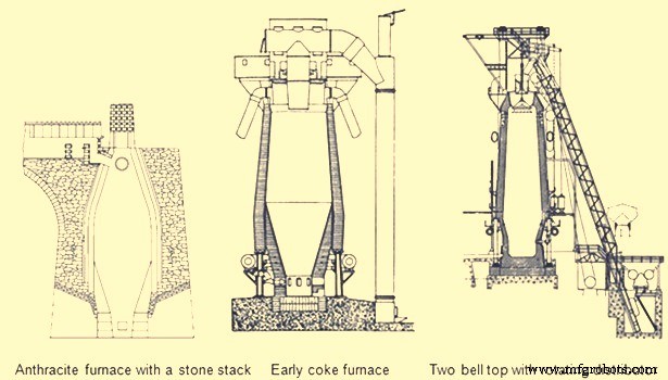
Fig 6 Early blast furnaces
The first important developments in brick making technology did not occur until the 1900s. In 1917, the first machine-made brick was introduced with its resulting increase in density and strength. In 1935, vacuum pressed bricks further improved brick quality. In 1939, super-duty alumina brick containing up to 60 % alumina was first available. In the 1930s, carbon blocks were used in German furnace hearths. Today many varieties of alumina, carbon, and silicon carbide refractories are available for BF lining. The improvements in furnace cooling and lining have increased typical campaign lengths from two years in the 1880s to more than ten years in the 1990s. Today campaign life of BFs has further increased to 20 years.
Another area of the BF which was forced to change with increased production was the casting operation. The old style tymp and dam open front of the furnace was no longer adequate. In 1867, the Lurman front was patented to eliminate the tymp and dam. It consisted of a cast iron panel which was water cooled and had separate openings for iron removal (still known as a tap hole) and for slag removal (known as the slag or cinder notch). This design was changed by the 1880s by rotating the slag notch 90 deg from the tap hole. Both the tap hole panel and slag notch panel were water cooled. By separating these two liquid tapping points, more room was available to set up the furnace for the increasing number of casts required at higher production rates. The area in front of the tap hole was completely available for pig beds while the slag pits were moved around to the side of the furnace (Fig 5). During normal operation, the slag notch was opened with a bar as the liquid slag level approached the tuyeres. The slag was flushed into pits or special slag cars. When the slag notch blew wind out of the opening, it was closed with a manual stopper. By tapping the slag off between iron taps, a greater volume of the hearth was available for liquid iron which resulted in larger cast tonnages. The iron casting process in the 1880s did not change much from previous operations but pig beds were bigger and in 1909 a slag skimmer was installed to skim the floating slag off of the iron as it flowed down the trough.
In 1896, the installation of a pig casting machine invented by EA Uehling finally brought about the complete elimination of the pig bed in the cast house. Next the open-top brick lined ladles were introduced. These ladles carried about 10 tons to 100 tons of hot metal and required the furnace and cast house to be elevated above ground level so the ladles could be placed under the cast house floor. Though the pig beds have got eliminated but troughs and runners remained and spouts going into the ladles were added to the cast house. In 1915, there was first use of the torpedo type ladles. These railroad mounted ladles carried 90 tons but were increased to 150 tons by 1925. Today, the iron ladle design is similar but capacities up to 400 tons are available. Open-type ladles mounted on rail cars are still used today.
Prior to 1890, the tap hole was opened with a bar and sledge hammer. Then in 1890 the first pneumatic rock drill was used. The tap hole was manually stopped with wind off the furnace until 1914 when HA Berg developed the remote controlled mud gun which pushed a clay plug into the furnace with a wind on. In 1906, the first oxygen lancing was used to melt skulls in the tap hole. Modern BFs have evolved to include remote controlled tap hole drills, hydraulic mud guns, cast house slag granulation units and iron tilting spouts to feed an unlimited number of iron ladles. BFs may also have from one to four tap holes and two to six slag pits depending on their size. Removing the bottleneck in the cast house allowed the first 1000 ton/day operation in 1929 and led to 1990s production levels of 12,000 ton/day.
A parallel line of improvement activities which rapidly evolved starting in the late 1800s was iron ore preparation. Iron ore used in iron making consists of many geological forms such as red hematite, specular hematite, magnetite, limonite, fossil ores, bog ores and carbonates. The metallic iron content of these ores ranges from approximately 30 % in the bog ores to 72 % in some hematites. All iron ores are mixed with other compounds in the earth which are undesirable in the smelting process. Beginning in the 1700s, iron ore was roasted with charcoal in open pits or enclosed kilns. The object of roasting or calcining was to liberate all volatile constituents, such as water, carbonic acid or bituminous substances, and to soften and crack the ores, making them more permeable to reducing gases. In the 1800s, iron ore screening was introduced to more closely size the ore for improved gas permeability inside the furnace. At first, hand screening equipment was used but, by the 1870s, steam-driven ore washers consisted of one or two drums that were perforated with holes or slots for the fine material to exit with the wash water while the final sized and washed ore exited the inside of the drum into a wheelbarrow or stockpile.
As iron production increased, the purest iron ores were depleted in many areas so lower grade ores had to be mined. These ores had undesirable impurities and methods to concentrate these ores to higher iron percentages were required. In 1880, Thomas A. Edison obtained a patent for an electromagnetic separator. A demonstration plant was built in Michigan and produced 893 tons of magnetic concentrate in 1889.
Pilot plants to pelletize taconite concentrates were built in 1948. By 1956, two commercial-scale taconite mining and processing operations were producing pellets. The first straight grate pellet machine was made in 1956 and the first grate-kiln pellet machine was put into operation in 1960. Pelletizing technology spread throughout the world from the US. The newest development in pelletizing was the introduction of raw limestone, dolomite or olivine into the pellet to improve its metallurgical properties which, in turn, improved BF productivity and fuel rates.
Iron ore agglomeration also took a separate route from pelletizing earlier in the 1900s. Sintering process originated in the nonferrous industry as a batch process in the late 19th century. Up to the 1950s, most sinter had a basicity ratio of less than 1.0. However, over the next fifteen years, it was realized that a basic sinter with a basicity ratio of more than 1.0 brought a pre-calcined flux source into the BF which resulted in a fuel rate savings.
One of the final technological improvements in iron making over the last 100 years has been tuyere level injectants. The first recorded use of injectant was in 1871 when there was a chilled hearth on the Morgan charcoal furnace. Because blast could not enter the tuyeres due to chilled material, a hole was punched through the furnace wall above the salamander and a large tuyere was installed. Coal oil was then forced under pressure into the tuyere from a pipe running from the top of the furnace. Six days and seven barrels of oil later the salamander had been melted and the furnace was running smoothly. In the first decade of the 1900s early tests with oxygen injection were made in the small BF in Belgium. The first large scale oxygen enriched blast was used in 1951. The benefits of pure oxygen injection are increased BF production due to increased fuel burning capacity and an ability to use more hydrocarbon tuyere injectants. The evolution of hydrocarbon injectant occurred in the 1940s and 1950s. In 1944, William L. Pogue submitted a patent for the use of coal injection. Then in 1953, natural gas injection was implemented. In the early 1960s, injection of oil and tar through lances was developed at numerous steel companies after substantial coke savings were proven by testing in an experimental BF in 1959. By 1967, a large number of the BFs were using some form of fuel (mostly pulverized coal) injection. Today, many BFs use fuel injectants 40 % to 45 % of the fuel rate. The final tuyere injectant, which evolved concurrently with fuel injection, was moisture injection. Historically, hot blast temperatures were limited as excessively high temperature combustion zones resulted in poor burden descent. The injection of moisture consumed coke more rapidly than air alone and produced a gas that was both richer in carbon monoxide and hydrogen and was less dense. These factors improved the rate of heat transfer between gases and solids and the rate of reduction of the burden in the furnace stack, which resulted in a smooth running furnace.
The combination of moisture injection, fuel injection and oxygen injection permitted the increase of hot blast temperature and the use of all of these tuyere level variables further improved productivity and reduced fuel rates in modern BFs.
Evolution of BF iron making as a science
Historically, iron making was more an art than a science. Early iron producers learned their trade through years of training from the previous generation. Many improvements in iron making practice were based on instinct or pure luck. However, by the mid-nineteenth century, science was creeping into the developments in iron smelting.
Charles Schinz of Germany, one of the earliest researchers of chemical and physical phenomena occurring inside a BF, attempted to make quantitative mass and energy balances of BF operation but he was severely limited by the lack of accurate thermodynamic data. He conducted laboratory experiments to determine heat capacity and heats of formation and was apparently the first to determine the reducibility of iron ore. He defined different zones of the BF and the major chemical reactions taking place in each zone. The results of his work were published in 1868.
Several principles which are recognized today were postulated by Sir Lothian Bell, during the late 1800s. He published a book in 1872 which is recognized as the first text book on BF iron making. In 1884, he was seemingly the first to document the function of the different slag components and their effect on melting temperature. He also observed that BF slags are complex structures and there is a range of slag compositions which results in its good fluid properties and desulfurizing capability. His most important contribution was his understanding of chemical reactions. He recognized the importance of CO and CO2, and was the first to start defining equilibrium in the Fe-O-C system. Further, Bell discussed preheating and pre-reduction of iron ores and the importance of the furnace stack where these reactions occurred. He also made carbon, oxygen and nitrogen balances of the BF operations and showed that some of the charged carbon was consumed in the stack by CO2 in the ‘solution loss’ reaction.
A contemporary of Bell was ML Gruner, a professor of metallurgy in France, further expanded Bell’s methods of determining BF heat balances by comparing many different furnace operations. He also believed that the minimum fuel rate for BFs would be achieved when solution loss was eliminated.
JE Johnson, Jr. was the first American scientist to explore the BF process and published two books on BF design and operation in the early 1900s. He applied the first and second laws of thermodynamics to iron making and explained how fuel rate was impacted by blast temperature. He postulated that there was a critical furnace temperature above which a minimum amount of heat is required. This minimum amount of heat he called ‘hearth heat’. In his book, published in 1913, Johnson produced a diagram showing chemical reactions and isotherms in the BF. The application of the critical temperature and hearth heat concepts further convinced furnace operators that the BF process was rational and predictable.
During the period from 1920 to 1930, the flow of solids and gases in the BF was studied extensively by a group of workers named PH Royster, SP Kinney, CC Furnas, and TL Joseph. This group was interested in physical and chemical phenomena occurring in BFs and in order to understand these phenomena they felt it was necessary to sample and probe operating furnaces. Their work started with a small experimental BF and spread to commercial furnaces. The results of their studies showed that the flow of gases and solids was not uniform across any horizontal plane in the BF and that improving gas-solid contact in the stack of the furnace could significantly increase the efficiency of the iron making process. Furnas and Joseph continued this work and determined that raw material size and reducibility was critical in gas-solid reactions. This important work led to the understanding of burden distribution and the optimization of iron ore sizing as it impacts both reducibility and permeability.
In 1962, R. Stephenson explained the role of solution loss. Previously, it had been thought the production of CO by reacting with CO2 and carbon was a waste of fuel. Stephenson pointed out that iron oxide reduction is a combination of indirect reduction and direct reduction and that indirect reduction followed by solution loss is direct reduction. Using these considerations to determine carbon rates for all combinations of these two reduction routes as a function of solution loss, results can be plotted on the ‘carbon-direct reduction diagram’. In the 1960s and early 1970s, the best applications of these BF theories were put into practice in Japan. Currently, the Japanese improvements have spread in the form of large, highly automated BFs to other places.
The theory and practice of iron smelting technology have come a long way in the last 4000 years. The transition from sponge iron produced in forges to liquid iron produced in BFs in the 1300s was the first major step in advancing iron making technology. Then came the change from cold blast, charcoal furnaces to hot blast, coke furnaces in the mid-1800s which brought iron making into the modern era. The better understanding of iron making reactions and improved equipment evolved into the hard-driving furnace operation centered in the 1880s to 1900s. Finally, the revolution in scientific applications to iron smelting, the installation of more sophisticated equipment, and the advent of electronically controlled systems has accelerated BF iron making into the current state as demonstrated by the operation of around 12,000 tons/day BFs with fuel rates less than 460 kg/ton.
Proceso de manufactura
- Plancha para ropa
- Hierro
- Generación y uso de gas de alto horno
- ITmk 3 Proceso de fabricación de pepitas de hierro
- Uso de coque de nuez en un alto horno
- Inyección de carbón pulverizado en un alto horno
- Irregularidades del alto horno durante la operación
- Sistema de enfriamiento de alto horno
- Sistemas de carga superior de alto horno
- Química del Proceso de Fabricación de Hierro por Alto Horno
- Fabricación de hierro por alto horno y emisiones de dióxido de carbono