


Aspectos importantes del diseño de Altos Hornos y equipos auxiliares asociados
Aspectos importantes del diseño de Alto Horno y equipos auxiliares asociados
El diseño del alto horno (BF) propiamente dicho y sus equipos asociados y auxiliares (Fig. 1) inmediatamente aguas arriba y aguas abajo del horno es importante para el funcionamiento eficiente del BF. Además del horno propiamente dicho, los equipos asociados inmediatos incluyen (i) el almacén, (ii) el equipo de carga, (iii) la parte superior del horno, (iv) el sistema de enfriamiento y (v) el equipo del área de fundición.
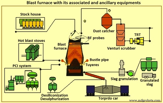
Fig. 1 Alto horno con sus equipos asociados y auxiliares
La fabricación de hierro BF consiste en un sistema compuesto por varios componentes que funcionan en armonía. La aplicación y el funcionamiento adecuados de estos componentes son necesarios para respaldar el proceso de fabricación del hierro. La selección de componentes específicos depende de factores tales como las condiciones existentes, las limitaciones físicas, los requisitos de producción, el costo, el cronograma, la confiabilidad y la capacidad de mantenimiento. La interdependencia de los componentes es tan importante para el funcionamiento exitoso del sistema como su capacidad individual. Existen requisitos importantes y prácticas "normales" para cada área o componente. También hay algunas tecnologías alternativas disponibles comercialmente que tienen ventajas y desventajas inherentes.
BF convierte la carga de mineral que contiene hierro en hierro líquido (metal caliente). Asociadas con el BF hay baterías de hornos de coque que convierten el carbón en coque, y plantas de sinterización y peletización, que preparan el mineral de hierro para el BF. El BF convierte estas materias primas preparadas en un producto de mayor valor. El metal caliente de algunas de las operaciones de BF se utiliza en fundiciones para la producción de piezas de fundición de hierro. Otras operaciones producen un metal caliente con menos silicio que se convierte en acero en un taller de fundición de acero. Parte del metal caliente se convierte en arrabio en las máquinas de fundición de lingotes. Los subproductos de BF son escoria, gas superior de BF, polvo de combustión y torta de filtración. Estos subproductos pueden tener un impacto económico positivo o negativo, según las posibilidades locales de aprovechamiento.
Algunos de los varios aspectos que afectan cada consideración para el diseño o rediseño de BF son (i) ganancias, (ii) salud y seguridad de los empleados, (iii) protección ambiental, (iv) regulaciones legales, (v) necesidades del mercado y procesamiento posterior, (vi) recursos humanos, de construcción y de mantenimiento disponibles, (vii) tecnologías cambiantes y obsolescencia de equipos, (viii) materias primas disponibles, servicios públicos y otros materiales, y (ix) así sucesivamente. Cualquier restricción seria en cualquiera de estos aspectos puede poner en riesgo la viabilidad de la unidad BF (o incluso una planta siderúrgica) o impedir o hacer necesaria la construcción de una nueva BF.
Los BF normalmente se agrupan por tamaño. Los mini BF producen menos de 1500 toneladas de metal caliente por día (tHM/día), los BF pequeños producen en el rango de alrededor de 2500 tHM/día a 5000 tHM/día, los BF medianos producen en el rango de alrededor de 6000 tHM/día a 8000 tHM/día, y los BF grandes producen alrededor de 9.000 tHM/día a 12.000 tHM por día. En una planta siderúrgica integrada, se necesita una cantidad y tamaño de BF para proporcionar el metal caliente requerido para la producción de acero. Las plantas siderúrgicas integradas con varios BF se ven menos afectadas cuando un BF se somete a reparaciones de revestimiento o cuando hay problemas de control del horno. Los BF pequeños tienen reparaciones de revestimiento más breves que los BF grandes y se consideran más fáciles de operar. Sin embargo, el costo del metal caliente de los BF pequeños es mayor. Se requiere que la planta siderúrgica integrada opere el número mínimo de hornos rentables. En algunos casos, se realizan actualizaciones para reducir la cantidad de hornos en funcionamiento.
Los BF se rebasen periódicamente después del final de su campaña (tiempo entre la reparación del rebase). En el pasado, esto implicaba el reemplazo del revestimiento interno de ladrillos del horno principal. En los últimos tiempos, la reconstrucción, el reemplazo y el mantenimiento preventivo de componentes extensos se realizan al mismo tiempo. Con esta práctica, la planta de acero más eficiente con menos BF grandes pierde un mayor porcentaje de su producción durante la reparación del revestimiento del BF que la planta con más hornos pequeños. Para tener tanto el bajo costo operativo como la mínima interferencia durante el cambio de revestimientos BF, la industria ha trabajado para maximizar la campaña de los BF y reducir la duración de la reparación del revestimiento. La clara tendencia actual en las plantas siderúrgicas integradas es operar menos hornos grandes y utilizar técnicas y diseños que extiendan la campaña de BF indefinidamente.
Al mismo tiempo, ha cobrado mayor importancia la reducción de la variabilidad del producto, por lo que se están realizando inversiones en automatización que mejoran el seguimiento y control del proceso. Los operadores de BF, el personal de mantenimiento, los diseñadores y el personal de investigación han aplicado tecnología moderna y métodos analíticos al proceso de BF para monitorear y controlar mejor el proceso. Como resultado, se ha reducido la desviación estándar de la calidad del metal caliente. Los sistemas mejorados de recopilación de datos también brindan mayor información a los proveedores y fabricantes. Esto ha mejorado la selección de materiales y el diseño de los BF y el equipo asociado. La duración de las campañas ha aumentado a alrededor de 20 años antes de 5 años a 10 años.
La fabricación de hierro BF es una tecnología de más de 430 años. Aun así, el uso de metal caliente BF sigue siendo el método más común utilizado en las plantas siderúrgicas integradas para la producción de acero. Los procesos integrados de las plantas siderúrgicas actuales dependen de la BF para proporcionar cantidades predecibles de metal caliente de calidad constante según lo programado. La variación en cualquiera de los aspectos del suministro de metal caliente tiene un grave impacto en el resto de procesos productivos del acero. De ahí que el BF siga siendo un proceso clave en las modernas acerías integradas.
A veces se afirma que la tecnología de proceso BF está al final de su vida útil. Esto no es así. El estudio de los datos operativos de 23 años (1970 a 1993) de un par típico de BF de tamaño mediano ha demostrado que hay un aumento promedio en la productividad del 3 % anual (Fig. 2a). Al mismo tiempo, la reducción promedio en la tasa de combustible ha sido del 1 % anual (Fig. 2b). Además, se ha ampliado el tiempo productivo entre el revestimiento de BF (la campaña) mediante mejoras en equipos, materiales y diseño. Como resultado, el costo total de producción de metal caliente, corregido por inflación, ha mejorado incluso más de lo que indican los datos operativos. Por lo tanto, la tecnología de proceso BF no está muerta, aunque es una tecnología de más de 430 años. Todavía está progresando en todas las áreas a un ritmo considerable. La BF sigue siendo hoy una ciencia dinámica respaldada por tecnologías en constante mejora.
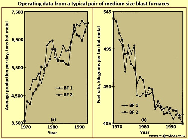
Fig. 2 Datos operativos de un par típico de altos hornos de tamaño mediano
Disposición del BF
El diseño de un BF es esencialmente un ejercicio de integración del equipo necesario para manejar los diferentes materiales necesarios para fabricar metal caliente y el producto y los subproductos resultantes. El diseño más eficiente se adapta adecuadamente a todo el proceso y su eficacia se juzga desde el punto de vista tanto de la inversión de capital inicial como de los costos operativos continuos. El diseño del taller BF depende de varios factores, como (i) el terreno del sitio, (ii) las condiciones climáticas, (iii) el método de entrega de la materia prima, (iv) los sistemas y ubicaciones de procesamiento de la materia prima en la planta, (v) los sistemas de procesamiento aguas abajo y ubicaciones, (vi) requisitos de cantidad/flujo de metal caliente, (vii) tipo y tamaño de la flota de entrega de metal caliente, y (viii) así sucesivamente. La figura 3 muestra un diseño simplificado de una planta BF.
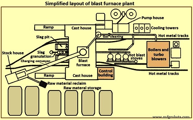
Fig. 3 Diseño simplificado de una planta de alto horno
Una planta BF consta típicamente de varias secciones. Estas secciones son (i) almacenamiento, manipulación y recuperación de materia prima, (ii) almacén, (iii) sistema de carga, (iv) horno propiamente dicho, (v) fundición, (vi) procesamiento y manipulación de escoria, (vii) manejo de metales calientes, (viii) estufas de chorro caliente y sistema de chorro caliente, (ix) planta de limpieza de gas, (x) servicios públicos, (xi) sistema de automatización y control, (xii) instalaciones de mantenimiento y (xiii) instalaciones de apoyo al personal.
Almacenamiento y manipulación de materias primas
Las materias primas, como el mineral de hierro, el sinterizado, los gránulos, los fundentes, el carbón y el coque, etc., se reciben de fuentes externas o se producen dentro de la planta siderúrgica integrada. Estas materias primas necesitan un almacenamiento controlado suficiente para respaldar las operaciones de BF. La capacidad de almacenamiento es necesaria en caso de interrupciones de entrega predecibles o interrupciones impredecibles. Se puede necesitar capacidad de almacenamiento adicional en caso de posibles cambios en la fuente de ciertas materias primas. Se necesitan lugares de almacenamiento separados debido a las diferentes características físicas o químicas en materiales similares. La mezcla de materiales similares puede causar problemas metalúrgicos o de control del proceso. Las pilas de almacenamiento deben separarse para evitar la mezcla de materiales diferentes. Las pilas deben colocarse sobre camas preparadas para permitir que los operadores de equipos de recuperación de materia prima distingan entre materia prima y materia residual. Las pilas se colocan para minimizar la degradación del material y evitar que el viento levante los finos. Se pueden usar rociadores de agua y agentes protectores para minimizar la captación/transporte de polvo por los vientos.
Varias técnicas diferentes están disponibles para el depósito y recuperación de materia prima. Las técnicas de depósito incluyen volcado de vagones, puentes de mineral, transportadores de apilamiento, raspadores, etc. Las técnicas de recuperación incluyen recuperadores de ruedas de cangilones, recuperadores de dobladoras, cargadores frontales, raspadores, directamente desde el fondo de contenedores o pilas, etc. Es obvio que el depósito y la recuperación los sistemas deben dimensionarse para garantizar el rendimiento necesario para la planta BF.
Almacén
El almacén es la unidad de almacenamiento del operador BF para la alimentación directa de la carga al horno. Se proporcionan contenedores de almacenamiento para cada uno de los materiales de carga para el BF. Se proporcionan contenedores individuales para materiales similares (es decir, sinterizados, gránulos) que tienen diferentes propiedades metalúrgicas. El almacén proporciona la capacidad adecuada para los diversos materiales de carga en caso de una interrupción a corto plazo del suministro desde las áreas de almacenamiento de materias primas. Las capacidades típicas de rendimiento del silo en el almacén, en caso de pérdida de alimentación de materia prima, son (i) coque:de 2 a 8 horas, (ii) materiales que contienen hierro (mineral, sínter y gránulos):de 4 a 16 horas, y fundentes y otros materiales misceláneos – 8 horas a 24 horas. Estas capacidades se basan en la producción nominal del horno y varían según la confiabilidad y el tiempo de acceso para su reemplazo del inventario o de un proveedor.
Los materiales de carga tienden a degradarse debido a las condiciones climáticas y al manejo repetido. Cuanto mayor sea el número de veces que se manipule el material (almacenamiento, recuperación, descarga, canaletas transportadoras, cangilones puente de mineral, etc.), mayor será el porcentaje de finos en la carga. El proceso BF necesita una permeabilidad controlada y, por lo tanto, una carga controlada. La carga de finos excesivos, ya sea normalmente a lo largo de la carga o concentrada en períodos cortos de carga específicos, puede interrumpir el proceso de BF y dañar el equipo del horno. El almacén proporciona la última oportunidad razonable para eliminar los finos antes de cargarlos en el horno. Siempre que sea posible, se instalan cribas vibratorias después de los depósitos de almacenamiento de coque, mineral, sínter y gránulos para eliminar la mayor parte de los finos. Los finos eliminados se recogen para su reciclaje. Algunos operadores de BF cobran multas en áreas específicas del horno para ajustar la permeabilidad local del horno y controlar las cargas de calor en las paredes del horno.
Los medidores de humedad se proporcionan con frecuencia en el almacén para controlar las cantidades reales de agua cargadas en el horno. Esta información permite realizar ajustes en las cantidades de carga para compensar las condiciones ambientales variables (es decir, mayor humedad del coque durante el período de lluvias).
Dado que se necesitan diferentes tipos y cantidades variables de material de carga para respaldar la operación continua del BF, los materiales de carga deben proporcionarse en una secuencia específica (que a su vez se puede cambiar con frecuencia para admitir los parámetros operativos variables del horno). Por lo tanto, el almacén debe contar con equipos confiables para extraer y alimentar cantidades precisas de materiales de carga específicos para cumplir con un programa específico. La Fig. 4 muestra la disposición simplificada del equipo en el almacén.
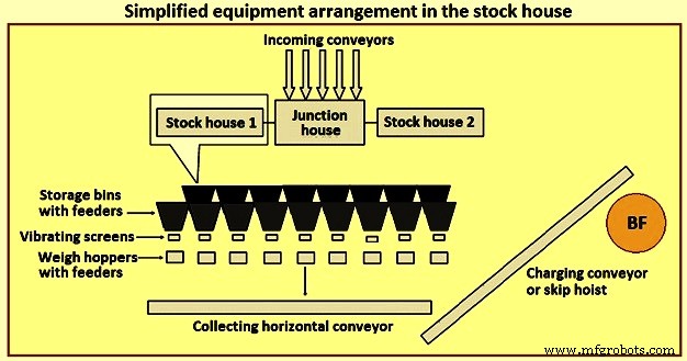
Fig. 4 Disposición simplificada del equipo en el almacén
Anteriormente, el tipo más común de casa de almacenamiento ha sido el tipo highline. Este tipo de almacén se encuentra directamente adyacente al horno. Los vagones de ferrocarril o las grúas puente alimentan el contenedor de almacenamiento, mientras que los contenedores de almacenamiento alimentan directamente a un vagón de escala móvil. Un operador de carro de báscula controla manualmente la compuerta de descarga del contenedor para alimentar cantidades específicas de material en la tolva equipada con báscula ubicada en el carro de báscula. Después de recolectar los tipos y cantidades adecuados de material, el operador mueve el carro de la báscula a una posición sobre el "pozo del contenedor" y descarga la carga, a través de un conducto, en un carro del contenedor que espera. Luego, el vagón volquete se eleva a la parte superior del horno.
El tipo de almacén de línea alta, junto con un carro a escala, ha presentado pocas opciones para la provisión de cribado de carga ferrosa (mineral, sinterizado y gránulos). A medida que ha aumentado el conocimiento del proceso BF, se han desarrollado requisitos más estrictos para la carga. El concepto de "carga diseñada" está bien reconocido hoy en día en la industria. Normalmente se acepta que existen límites a la flexibilidad y adaptabilidad del almacén de material highline para cumplir con este requisito. Por lo tanto, el patio de almacenamiento de tipo highline ha sido reemplazado por el almacén de almacenamiento automatizado con cinta transportadora para suministrar materiales de carga al BF.
El almacén automatizado es normalmente de dos tipos distintos y distintos. El primer tipo es el reemplazo del carro de báscula debajo de los contenedores de materia prima con un sistema de alimentación y cinta transportadora. Se proporcionan transportadores separados para cada tipo de materia prima (coque, materiales que contienen hierro y materiales fundentes y aditivos, etc.) sobre los cuales se montan filas de silos de almacenamiento, con alimentadores vibratorios para descargar materiales de carga desde los silos de almacenamiento a los transportadores. Para los materiales que contienen coque y hierro, se ubica una criba vibratoria en la descarga de cada transportador para cribar el material y alimentarlo a las tolvas de pesaje. Este tipo de sistema continúa alimentando las tolvas de pesaje delante de los carros basculantes.
El segundo tipo de almacén automatizado es una gran estructura de contenedores de almacenamiento construidos completamente sobre el suelo y bastante alejados del BF. Esto normalmente se hace para los BF en los que se utiliza una cinta transportadora para llevar los materiales de carga a la parte superior del horno en lugar de los carros basculantes. El método de llenado de los contenedores de almacenamiento es normalmente mediante un sistema de cinta transportadora. Las materias primas se extraen de los contenedores de almacenamiento mediante alimentadores vibratorios y cintas transportadoras hacia las tolvas de pesaje. Las tolvas de pesaje, a su vez, descargan el material sobre el transportador principal por medio de un transportador colector. Las tolvas de pesaje están programadas para pesar las materias primas en el orden correcto en la cinta transportadora principal hasta la parte superior del horno.
La provisión de un almacén automatizado puede proporcionar una alimentación más eficiente de materia prima al almacén y una selección, cribado, pesaje y entrega de la carga al horno más eficientes. La casa de apilamiento automatizada se puede ubicar directamente junto al vagón contenedor de alimentación del horno, o se puede ubicar lejos del horno para cargar a través de una cinta transportadora.
La automatización del almacén aumentó considerablemente la capacidad de producción, mejoró la eficiencia operativa y eliminó las variaciones operativas causadas por los operadores y el equipo. Sin embargo, en la práctica, un almacén moderno y automatizado puede ser bastante complejo. El almacén en sí mismo puede ser alimentado por transportadores, que a su vez descargan en transportadores de disparo para distribuir materiales a varios contenedores. La disposición de los transportadores y equipos en el almacén se puede organizar de muchas maneras. La ubicación del depósito de almacenamiento junto al horno con frecuencia genera congestión en el diseño y restringe la flexibilidad para futuras modificaciones.
Sistema de elevación
Los materiales de carga normalmente se elevan a la parte superior de BF con la ayuda de carros basculantes o mediante una cinta transportadora.
Omitir elevación de vehículos – El uso de vagones basculantes para BF evolucionó a partir de la industria minera. Los carros basculantes BF están dimensionados para adaptarse al rendimiento del horno. Obviamente, varios factores, como la capacidad del polipasto, el diseño del puente volquete, etc., tienen sus propias influencias o limitaciones en el tamaño del volquete.
Normalmente, dos contenedores funcionan de forma opuesta (para reducir la potencia de elevación necesaria) en un polipasto común. Los volquetes viajan sobre rieles en un puente volquete, normalmente instalado con una inclinación alrededor de 60 grados a 80 grados con respecto a la horizontal. El volquete completo acelera lentamente al salir del foso del volquete, acelera lo más rápido posible alcanzando y viajando a la velocidad máxima durante la mayor parte del ascensor. El polipasto reduce la velocidad del contenedor a medida que se acerca a la parte superior del puente del contenedor. Las ruedas de la tolva son guiadas por los rieles de descarga y bocina a medida que la tolva se vuelca en el equipo de carga superior del horno. A medida que el contenedor de elevación alcanza y se detiene en la posición de descarga final, el contenedor vacío (descendiendo a las mismas velocidades) está llegando al final de su recorrido hacia el foso del contenedor, esperando el llenado. El sistema de carga salteada es una técnica confiable y efectiva para entregar la carga a la parte superior del horno. Sin embargo, carece de flexibilidad para el operador, ya que los contenedores solo pueden contener una cantidad específica de material (la sobrecarga da como resultado un sobrellenado o cargas de elevación excesivas) o se vuelve ineficiente si se necesitan pequeños volúmenes de carga específica. La Fig. 5 muestra un esquema de elevación de vagones basculantes.
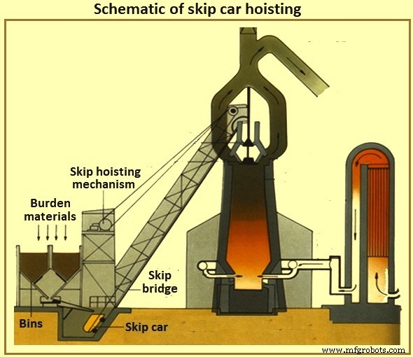
Fig. 5 Esquema de elevación de vagones de contenedores
Transportador de carga del horno – Con la transportadorización del almacén ha llegado la transportadorización del sistema de elevación. Ahora es común que las casas de almacenamiento estén ubicadas lejos del horno y una gran cinta transportadora lleva la carga a la parte superior del horno. Si la parte superior del horno tiene alrededor de 60 metros de altura, entonces una cinta transportadora instalada con una inclinación de 8 grados en posición horizontal, el almacén debe ubicarse al menos a 427 metros del horno. Las inclinaciones más pronunciadas de la banda normalmente se evitan para minimizar el retroceso del material. Es normal cargar materiales misceláneos directamente sobre y después del final de una carga ferrosa en la cinta transportadora para mantener los materiales ferrosos en su lugar hasta que lleguen a la parte superior del horno.
Sistema de carga en la parte superior del horno
El horno propiamente dicho funciona con alta presión superior positiva. El proceso BF genera gas BF que consiste parcialmente en monóxido de carbono, dióxido de carbono y nitrógeno junto con grandes cantidades de polvo arrastrado. El operador de BF debe mantener la presión máxima debido a los beneficios del proceso y contener los gases y el polvo (tanto para el valor del combustible como para fines de control ambiental). Sin embargo, el operador debe colocar regularmente material de carga dentro de la parte superior del horno para reponer el proceso interno, sin perder la presión superior del horno.
Top tipo campana – Durante varios años, el tipo más común de tapa de horno ha sido la tapa de dos campanas (Fig. 6). A medida que la carga llega a la parte superior del horno (por tolva o transportador), cae en una tolva receptora y en la tolva de campana pequeña. La campana pequeña (fundición de acero de forma cónica de alrededor de 2,6 metros de diámetro y 1,4 metros de altura para un BF de 5.000 tHM por día) baja y permite que la carga caiga en la tolva de campana grande. La campana pequeña se levanta y se sella contra un asiento fijo en la tolva de campana pequeña. Dependiendo del volumen de la tolva de campana grande, la campana pequeña secuencia cargas adicionales en la tolva de campana grande. Durante todo este proceso, la gran campana ha permanecido cerrada sellando el horno. Cuando se han recopilado los números correctos de carga de la carga, la campana grande (fundición de acero de forma cónica de unos 5,5 metros de diámetro y unos 3,5 metros de altura para un BF de 5000 tHM por día) baja y permite que la carga se deslice por la campana hasta la parte superior del horno propiamente dicho. Una vez descargada la carga, se levanta la campana grande y se sella contra la parte inferior de la tolva de campana grande. La figura 6 muestra los sistemas de carga superior tipo campana BF.
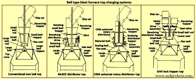
Fig. 6 Sistemas de carga superior de alto horno tipo campana
Obviamente, el control de distribución de la carga con el horno para este tipo de tapa está limitado por la uniformidad con la que se coloca la carga sobre la campana grande (el volcado por omisión da como resultado una colocación desigual de la carga en este tipo de tapa) y las curvas descendentes de la campana. materiales de carga específicos (es decir, coque o carga de hierro) a medida que se deslizan y caen de la campana grande. Además, la parte superior de las dos campanas es susceptible de perder el sellado de las campanas grandes y pequeñas y del empaquetamiento entre la varilla de la campana grande y el tubo de la campana pequeña. La fuga de la campana resulta de la abrasión por el material de carga que se desliza sobre las superficies de sellado de la campana. La fuga de la empaquetadura de la varilla es el resultado de la abrasión de los finos dentro del horno o de la acumulación en la varilla de la campana grande después de descargar la carga en la tolva receptora.
En un esfuerzo por minimizar el desgaste de la gran superficie de sellado de la campana, se introduce gas BF tomado del interior del horno entre las campanas para igualar el espacio (reduciendo el diferencial de presión a través de la gran superficie de sellado de la campana). Este gas se libera a la atmósfera antes de abrir la campana pequeña para permitir la introducción de más carga. Algunas de las opciones disponibles para mejorar las limitaciones del sistema de techo de dos campanas se dan a continuación.
El distribuidor McKEE – El distribuidor McKEE (Fig. 6) durante varios años fue la principal mejora de distribución de carga disponible para la parte superior de dos campanas. Sin embargo, está siendo reemplazado rápidamente por otras tecnologías. Su diseño incorpora la capacidad de girar la campana pequeña y la tolva de campana pequeña al mismo tiempo mientras se descarga el carro basculante. La carga se distribuye uniformemente en la tolva de campana pequeña, lo que mejora la colocación uniforme de la carga en la campana grande. Este tipo de tapa es propensa al desgaste de la campana pequeña y grande y la subsiguiente pérdida del efecto de sellado.
Distribuidor giratorio universal CRM superior – El distribuidor giratorio universal CRM (Centre Recherches Metallurgiques – Bélgica) (Fig. 6) fue desarrollado para eliminar la pérdida del efecto de sellado de campana pequeña. Se instalan dos campanas (una campana de sellado y una campana de material) en lugar de la campana pequeña normal. Una tolva de carga giratoria está montada en la campana de material. La campana de sellado está ubicada debajo de la campana de material y sella contra un asiento fijo. Durante la descarga del contenedor, la tolva de carga y la campana de cierre de material giran para llenar la tolva de manera uniforme. Cuando se completa el llenado, la rotación de la tolva se detiene. Cuando llega el momento de descargar sobre la campana grande, se bajan la tolva giratoria, la campana de material y la campana de sellado. La campana de sellado baja por debajo del asiento fijo. A la mitad del proceso de descenso, se detiene el descenso de la tolva y la campana de material y la campana de sellado continúan descendiendo hasta que alcanzan su posición de parada. A medida que se abre el espacio entre la campana de material y la tolva, la carga se descarga uniformemente en la tolva de campana grande. A medida que la carga sale del espacio, no entra en contacto con la superficie de asiento de la válvula de sellado, por lo que mantiene la capacidad de sellado superior. Este estilo de capota es capaz de mantener una presión interna de 0,2 MPa.
La tapa de CRM mejora la capacidad de sellado y la longevidad de las dos tapas de campana. Sin embargo, no proporciona una mejora dramática en la distribución de la carga del horno sobre el distribuidor McKEE y no elimina la vulnerabilidad de la gran superficie de sellado de la campana.
La parte superior de la tolva de bloqueo GHH – La parte superior de la tolva de bloqueo GHH (Fig. 6) es la modificación de la parte superior de dos campanas. Reduce la dependencia de la campana grande para mantener un sello de gas. La adición de tolvas de bloqueo con válvulas de sellado separadas para cada ubicación de volcado de contenedores brinda una capacidad adicional para sellar la parte superior. La campana grande se puede operar sin presión diferencial a lo largo de su superficie de sellado (es decir, la presión superior del horno es igual a la presión de la tolva de campana grande). La operación se da a continuación.
Un contenedor vuelca la carga en la tolva de bloqueo a través de una tolva receptora y una válvula de sello abierta. La carga se coloca sobre la campana pequeña giratoria y llena uniformemente la tolva distribuidora giratoria por encima de la campana pequeña. Un sello entre la tolva de bloqueo y la tolva de campana pequeña giratoria está abierta mientras la rotación está en marcha. Cuando finaliza la descarga de la carga del contenedor, la válvula de sellado y el sello entre la tolva de bloqueo y la tolva de campana pequeña se cierran. Se introduce gas de ecualización y la tolva de bloqueo se presuriza a la presión superior del horno. Luego se baja la campana pequeña para introducir la carga en la tolva de campana grande. La campana pequeña se cierra y la presión de la tolva de la esclusa se libera a la atmósfera. Se abre la válvula de cierre del lado opuesto (es decir, en la otra posición de vaciado del contenedor). Se abre el sello entre la tolva de bloqueo y la tolva de campana pequeña. Comienza la rotación de la campana pequeña y la tolva. La parte superior ahora puede aceptar la carga del otro contenedor.
Este tipo de tapa mejora la capacidad de sellado y la longevidad de las dos tapas acampanadas. Sin embargo, la parte superior de la tolva de bloqueo no proporciona una mejora drástica en la distribución de la carga del horno con respecto a la parte superior McKEE o CRM. Aunque ya no se necesita la campana grande para realizar una función de sellado, la longevidad del efecto de sellado de la campana pequeña sigue siendo crítica.
Armadura móvil – El mayor paso dado para mejorar la distribución de la carga de la parte superior tipo campana fue el desarrollo de una armadura móvil (Fig. 7). Se instalan deflectores ajustables en el área de la garganta del horno para desviar la carga después de que se deslice fuera de la campana grande. La armadura móvil se ajusta según el material de carga específico que se descarga y el lugar donde el operador desea colocar la carga dentro del horno.
Varios fabricantes ofrecen diferentes tipos de armaduras móviles. Los segmentos de armadura individuales se pueden mover uniformemente (simultáneamente y por igual) dentro del horno para colocar la carga en un patrón anular. Hay otros tipos de armaduras móviles disponibles para proporcionar control individual de las placas de armadura para lograr un patrón de distribución no circular.
Algunas desventajas asociadas con la armadura móvil son (i) la mayoría de los componentes mecánicos y de desgaste se encuentran con el entorno hostil del cono superior del horno, (ii) se necesita cierta pérdida de volumen de trabajo interno para proporcionar espacio entre la armadura móvil y la línea de diseño. (aunque esta área del horno no puede clasificarse como una zona de productividad aproximada para la consideración del volumen de trabajo del horno, y (iii) capacidad limitada para desviar la carga al centro mismo del horno, particularmente cuando el nivel de la línea de almacenamiento ya es alto. La característica de los perdigones niega con frecuencia el desplazamiento limitado del blindaje móvil.
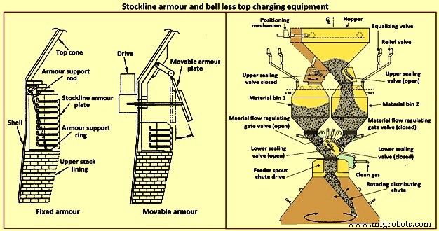
Fig. 7 Equipo de carga superior sin armadura y sin campana de Stockline
Sistema de carga superior sin campana – A principios de la década de 1970, Paul Wurth S.A. de Luxemburgo desarrolló el sistema de carga Bell Less Top (BLT) (Fig. 7). Este tipo de tapa de horno es una desviación radical de la tapa tipo campana. La carga se puede colocar dentro del horno en cualquier patrón que necesite el operador del horno. La colocación de anillos anulares, espirales, segmentos y puntos es un patrón común que se puede lograr mediante la inclinación y rotación sincronizadas o independientes de un conducto de distribución de carga ubicado con el cono superior del horno.
El sellado superior del horno se mantiene durante toda la campaña del horno. Las actividades de mantenimiento son simples y de corta duración. Normalmente, el BLT consta de una rampa o tolva de recepción (que recibe la carga de los contenedores o de una cinta transportadora), una tolva de bloqueo con válvulas de sellado superior e inferior, una compuerta de control de flujo de material, una caja de engranajes de accionamiento de la rampa principal (una caja de cambios de agua o gas). -unidad refrigerada utilizada para la rotación e inclinación del conducto) y el conducto de distribución de la carga. Hay tres tipos principales de BLT:(i) tolva paralela, (ii) alimentación central y (iii) tipo compacto.
Por lo general, el tipo paralelo incorpora dos tolvas de bloqueo (las tolvas se han instalado en algunos hornos para fines de rendimiento y respaldo; se ha instalado un tipo de tolva "excéntrica" para una aplicación con espacio libre restringido). Desde principios de la década de 1980, varios BF han seleccionado el tipo de tolva de bloqueo único de "alimentación central" por sus mejoras en la segregación de la carga y el control de la distribución de la carga, lo que da como resultado una mejor operación del horno.
Se ha desarrollado un tipo 'compacto' de tapa BLT para hornos de tamaño pequeño a mediano para permitir la introducción del BLT (y sus ventajas) en hornos donde los otros tipos más grandes de BLT no se pueden usar debido a limitaciones físicas o de costo. Los pasos en la operación BLT para un tipo de alimentación central son (i) la carga se descarga desde un contenedor o una cinta transportadora a través de un canal o tolva de recepción pasando una válvula de sello abierta hacia la tolva de la esclusa, (ii) después de que la carga se recibe en la esclusa tolva, la válvula de sellado superior se cierra y se introduce gas compensador para presurizar la tolva de bloqueo a la presión del horno, (iii) se abre la válvula de sellado inferior, (iv) la carga se descarga de la tolva de bloqueo cuando la compuerta de material se ha ajustado a la posición abertura preseleccionada para adaptarse al material de carga específico que se va a descargar, (v) la carga cae verticalmente a través del canalón del alimentador con la caja de engranajes de la transmisión principal y cae sobre el conducto de distribución de la carga, (vi) el conducto de distribución de la carga dirige la carga a la dirección requerida point(s) within the furnace, (vii) when the lock hopper is fully discharged (monitored by load cells and / or acoustic monitoring), the lower seal valve is closed, (viii) a relief valve is opened to exhaust the lock hopper to atmosphe re (or through an energy recovery unit), and (ix) the upper seal valve opens and the sequence is repeated.
The advantages of BLT over other top charging systems include higher top pressure capability (i.e. 0.25 MPa), fuel savings, increased production, more stable operation, reduced maintenance in terms of cost and time, increased furnace campaign life, and improved furnace operational control when employing high coal injection rates at the tuyeres.
Gimbal system of charging – The purpose of the Gimbal system of charging is to facilitate controlled distribution of charge material into the BF via a Gimbal type oscillating chute through a holding hopper and variable material gate opening such that the pressurized charging system above can operate independently of the distribution system. It utilizes a conical distribution chute, supported by rings in a Gimbal arrangement, producing independent and combined tilting of the chute axis. The Gimbal distributor, as part of the overall BF top charging system, offers a fully integrated charging solution, generating considerable improvement in BF operation and maintenance cost. The Gimbal system utilizes a conical distribution chute, supported by rings in a Gimbal arrangement, producing independent, and combined tilting of the chute axis.
The Gimbal top incorporates a full complimentary range of furnace top distribution equipment including distribution rockers, upper seal valves, hoppers, lower seal valves, material flow gates and goggle valve assemblies, all discharging through hydraulically driven distribution chutes. The tilting chute is driven by two hydraulic cylinders, mounted 90 degree apart. This type of suspension and drive arrangement results not in a rotation of the tilting chute, but in a circular path by superposition of both tilting motions. Independent or combined operation of the cylinders allows the chute axis to be directed to any angle, or even along any path. Motion is supplied by two hydraulic cylinders, each operating through a shaft, connecting rod, and universal joint in order to drive the Gimbal rings. Through the movement of the hydraulic cylinders, the distribution chute allows precise material distribution with potential for an infinite number of charging patterns at varying speeds. These include ring, spiral, centre, spot, segment or sector charging, providing complete control of material charging into the furnace.
The whole distributor assembly is enclosed in a gas tight housing, which is mounted directly onto the top flange of the BF top cone. The housing contains a fixed inlet chute and a tilting distribution chute supported by rings in a Gimbal arrangement allowing independent and combined tilting of the chute axis. The assembly is made from a combination of stainless and carbon steel material with the fixed inlet chute and tilting chute body lined with ceramic material to give superior wear protection. A closed-circuit water cooling system supplies cooling water through the main shafts, Gimbal bearings, and universal joint bearings in order to cool the moving elements of the Gimbal distribution system.
The key features of the Gimbal design are (i) simple, rugged design, using levers driven by the hydraulic cylinders, (ii) drive cylinders are mounted outside pressure envelope, hence not subject to hot and dusty service conditions, (iii) Gimbal ring arrangement gives simple tilting motion in two planes, which when superimposed gives 360 degrees distribution, and (iv) wear on the tilting chute is equalized around its circumference giving a long extended operational life.
The BF Gimbal top is an automated, computer-controlled pressurized charging system designed to (i) receive charges of ore, coke, and miscellaneous materials in the holding hopper, independently of the distribution system below, (ii) release those discharges, as needed, to a dynamic distribution chute located below the holding hopper, and (iii) distribute material in prescribed patterns to the furnace stock-line in accordance with a predetermined charging matrix. Control of the Gimbal distribution chute is fully integrated into the overall furnace charging software. The system provides a high level of accuracy and control for the Gimbal movements and hence the positioning of the distribution chute. Gimbal material distributor is shown in Fig 8.
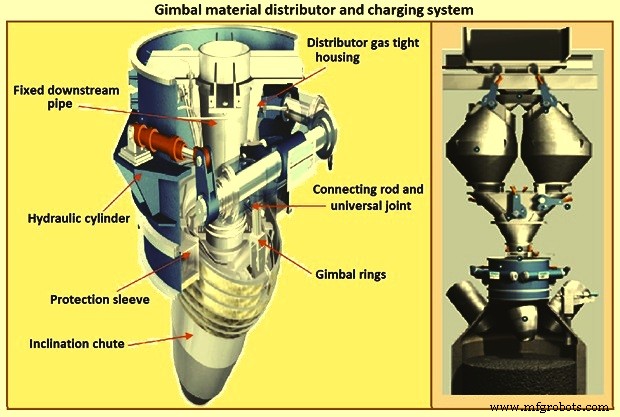
Fig 8 Gimbal material distributor and charging system
Furnace proper
The furnace proper is the main reactor vessel of the BF ironmaking process. Its internal lines are designed to support the internal process. Its external lines are designed to provide the necessary systems to contain, maintain, monitor, support, and adjust the internal process.
The BF process is a counter flow process. The process comprises of (i) burden at ambient conditions is placed in the furnace top onto the column of burden within the furnace, (ii) as the burden descends with the burden column, it is heated, chemically modified, and finally melted, (iii) further chemical modifications occur with the molten material, (iv) the molten products are extracted near the bottom, (v) melting of the burden material and extraction result in the descent of the burden column and the need for replenishment of the burden at the top, (vi) hot blast air is introduced through tuyeres near the bottom, (vii) BF gases are generated in front of the tuyeres and ascend through the burden and chemically modify the descending burden as well as themselves get chemically modified and cooled, (viii) BF gas (and dust) is extracted near the top of the furnace, and (ix) heat is extracted from the vessel in all directions (primarily through the lining cooling system) and along with the BF gas, liquid iron and liquid slag. Fig 9 shows cross section and types of BF.
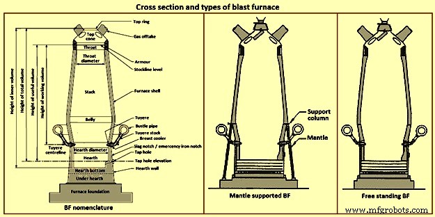
Fig 9 Cross section and types of blast furnace
Furnace type – Furnaces are constructed to be mantle supported or free standing. Mantle supported BFs characteristically have a ring girder (mantle) located at the bottom of the lower stack of the furnace. The mantle is supported in turn by columns which are on the main furnace foundation. The hearth, tuyere breast, and bosh are also supported by the foundation. Furnaces with mantle support column tend to have restricted access and reduced flexibility for improvements in the mantle, bosh, and tuyere breast areas.
Since thermal expansion is a major consideration in furnace shell design, the mantle style of furnace provides an interesting design consideration. The mantle support columns are relatively cool. The mantle tends to maintain a constant height, throughout the furnace campaign with respect to the furnace foundation. Thermal expansion of the stack due to process heat is considered to be based at the ‘fixed’ mantle (i.e. the top of the furnace raises with respect to the mantle). The effective height of the bosh, tuyere breast, and hearth wall shells (supported on the furnace foundation) increases due to the thermal expansion of the shell caused by the process heat. The lower portion of the furnace lifts upwards towards the fixed mantle. Hence, the provision of an expansion joint of some type is needed at the bosh / mantle connection or somewhere appropriately located in the lower portion of the furnace.
Free standing furnaces have been developed to eliminate the column and permit the installation of major equipment and furnace cooling improvements. This furnace type has a thicker shell for structural support. Installation and maintenance of a reliable cooling and lining system is necessary in order to sustain the structural longevity of the shell.
Two variations of the free standing furnace have been used. One type provides for a separate structural support tower to carry the furnace off-gas system and charging / hoisting system load. The other type (while it does employ a separate support tower for shell replacement purposes during relines) uses the furnace proper to support the off-gas system and charging / hoisting system loads. Special consideration to the furnace shell design is to be made regardless of the furnace type. The furnace vessel is subjected to internal pressures from the blast and gas, burden, liquid iron and slag. Dead and live load during all operating, maintenance, and reline stages are to be considered as well.
Furnace zones – The major zones of the furnace proper are (i) top cone, (ii) throat, (iii) stack, (iv) mantle / belly, (v) bosh, (vi) tuyere breast, (vii) hearth walls, (viii) hearth bottom, (ix) foundation.
Top cone – The top cone or dome is the uppermost part of the furnace proper. It supports the furnace top charging equipment, and the BF top gas collection system. Stock rods (stockline recorders or gauges) are normally placed here to monitor the upper level of the burden in the furnace. These devices are the units which provide the permissive or indication signals to charge the next scheduled burden input to the furnace. Typically, they are weights lowered by special winches, or microwave units. Some furnaces incorporate radio-active isotope emitters and detectors mounted in the furnace throat to monitor the burden level. Infrared camera can be installed in the top cone to monitor the BF top gas temperature distribution as it escapes the furnace burden stockline.
The top cone is the coolest zone of the furnace proper but can be exposed to extremely high temperatures if burden ‘slips’ (rapid, uncontrolled burden descent after a period of unusual lack of descent). The newly charged burden falls through this zone and the BF top gas is carried away from this section.
Throat – Steel wear plates or armour are installed in this zone. Here, abrasion of the furnace lining from the charged burden is the prime cause of deterioration. Furnace operators work to maintain the upper level of the burden (the stockline) in this region. Movable armour can be installed in this area in order to deflect the burden falling from a large bell. With the installation of the BLT, wear of the stockline area can be greatly reduced. Some BF users select to eliminate the armour plates and use an abrasion resistant refractory lining instead.
Stack – The stack (sometimes called shaft or the ‘in-wall’) is the zone between the mantle or belly on a free standing furnace and the stockline area. Smooth, uniform lines (the process ‘working surface’) of the stack are essential for uniform and predictable burden descent, BF gas ascent, and stable process control throughout the furnace campaign. Process considerations dictate a larger diameter at the base of the stack than at the top. Typical stack angles are in the range of around 85 degrees from the horizontal.
Mantle / belly – The mantle or belly area provides the transition between the expanded stack and bosh sections. Maintenance of the effectiveness of the cooling / lining system is particularly important for the mantle type furnace in order to protect the mantle structure. Thermal protection is important for the free standing furnace type as well. However, the free standing design is less complicated and more accessible in this area.
Bosh – The bosh area lies between the tuyere breast and the mantle / belly of the furnace. The bosh diameter increases from bottom to top. The inclination of the bosh permits the efficient ascent of the process gases and has been found to be necessary in order to provide the needed zone service life (the process gases are extremely hot and internal chemical attack conditions are severe). Typical bosh angles are in the range of around 80 degrees from the horizontal. Boshes are of two basic types, namely (i) banded and (ii) sealed. They can be cooled by different techniques.
Banded boshes are found in older mantle supported furnaces (they cannot be applied to free standing furnaces). A number of steel bands are placed in incrementally increasing diameters (smallest at the bottom of the bosh and largest at the top) and are tied together with connecting strips. Gap between the bands permits the introduction of copper cooling plates. Ceramic brick lining is to be used as air infiltration results in oxidation of carbon based linings. Gas leakage through the banded bosh can be high. This type is not suitable for BFs with high blast pressure / high top pressure. Banded boshes provide adequate flexibility to eliminate the requirement for a shell expansion joint in the lower portion of the furnace.
Sealed boshes, using continuous steel shell plate instead of separate bands, are employed to permit the use of improved cooling / lining systems, higher furnace operating pressures, and the free standing furnace type. Sealed boshes retain valuable gases with the furnace, hence improving the metallurgical process. As well, the seal bosh, since it precludes air entry into the lining, supports the use of carbon based refractories.
Tuyere breast – Hot blast air is introduced to the furnace through tuyeres (water-cooled copper units) located within the tuyere breast. The number of tuyeres needed depends upon the size (production capacity) of the furnace. The tuyere breast diameter, tuyere spacing, and number of tuyeres are influenced by the expected raceway zone size in front of each tuyere.
Tuyere stocks (Fig 10) convey the hot blast air from the bustle pipe to the tuyeres. The tuyeres are supported by tuyere coolers (water-cooled copper units) which are in turn supported by steel tuyere cooler holders (either welded or bolted to the furnace shell). Special consideration are to be made in the tuyere breast shell and lining design in order to maintain effective sealing of the different components in order to prevent escape and loss of the furnace gases.
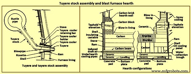
Fig 10 Tuyere stock assembly and blast furnace hearth
Hearth – The hearth (Fig 10) is the crucible of the furnace. Here, hot metal and liquid slag are collected and held until the furnace is tapped. The hearth wall is penetrated by tap holes (frequently called iron notches) for the removal of the collected hot metal and liquid slag. The number of tap holes is dependent upon the size of the furnace, hot metal, and liquid slag handling requirements, physical and capital constraints etc.
Several furnaces are equipped with a slag or cinder notch (normally one per furnace, although some furnaces can have two). The slag notch opening elevation is normally sufficiently higher than the iron notch elevation. In earlier days, when slag volumes were high, the slag was flushed from the slag notch periodically. This simplified the iron / slag separation process in the cast house. More commonly now, however, the slag notch is retained solely for initial furnace set-up procedures or for emergency use in case of iron notch or other furnace operating problems.
Hearth bottom – The hearth bottom supports the hearth walls and is flooded by the iron within the furnace. As the campaign progresses, the hearth bottom lining wears away to a fixed equilibrium point. The remaining refractory contains the process and with sufficient cooling or inherent insulation value protects the furnace pad and foundation.
Cooling system
The application of specific cooling techniques to individual furnace zones is dependent upon several factors such as campaign life expectancy, furnace operational philosophy, burden types, refractories, cost constraints, physical constraints, available cooling media, and preferences etc. Different cooling techniques can be provided for different zones to assist the lining to resist the specific zone deterioration factors. Normally, the provision of adequate cooling capacity is necessary in each of the applicable furnace zones if the lining system located there is to survive. Where the thermal, chemical, and to some extent the abrasive conditions of the process are extreme, sufficient cooling is to be provided to maintain the necessary uniform interior lines of the furnace and to protect the furnace shell.
Typically, the top cone and throat areas of the furnace are not cooled. The hearth bottom can be ‘actively’ cooled by under hearth cooling (air, water, or oil media) or ‘passively’ cooled by heat conduction though the hearth bottom lining to the hearth wall. The basic cooling options for the balance of the furnace are (i) no cooling (typically the upper portion of the stack is not cooled in several furnaces, (ii) shower or spray cooling, (iii) jacket or channel cooling, (iv) plate cooling, and (v) stave cooling.
Shower or spray cooling – Water is directed by sprays or by overflow troughs and descends in a film over the shell plate. Effective spray nozzle design, numbers and positioning are important for proper coverage and to minimize rebound. Proper deflector plate design is necessary to ensure efficient cooling water distribution and to minimize splashing. Shower cooling is frequently employed in the bosh and hearth wall areas. Spray cooling is normally applied for emergency or back-up cooling, primarily in the stack area. Exterior shell plate corrosion and organic fouling are common problems which can disrupt water flow or insulate the shell from the cooling effect of the surface applied cooling. Water treatment is an important consideration to retain effective cooling.
Jacket or channel cooling – Fabricated cooling chambers or indeed structural steel channels or angles are welded directly to the outside of the shell plate. Water flows at low velocity though the cooling elements in order to cool the shell and the lining. Jacket or channel cooling is frequently applied to the hearth walls, tuyere breast, and bosh areas. Scale build-up on the furnace shell and debris collection in the bottoms of the external cooling elements can compromise the cooling effectiveness. Hence periodic cleaning of the cooling elements is necessary.
The critical area of concern in the cooling schemes mentioned so far is the necessity for the shell plate to act as a cooling element. If extreme heat loads are acting upon the inside face of the shell, then there exist an extremely high thermal gradient across the shell. This effect results in high thermally induced shell stresses and eventual cracking. The cracks start from the inside of the furnace and propagate to the outside. The cracks remain invisible (other than a ‘hot spot’) until they fully penetrate the shell plate. Through cracking of the shell plate results in the leak of the BF gas, exposed shell carburization, and disruption of the cooling effect (particularly spray or shower cooling). Shell cracking into a sealed cooling jacket or channel is difficult to locate and can result in long furnace outage time for repair. Entry of water into the furnace (frequently when the furnace is off-line and internal furnace gas pressure cannot prevent entry of cooling water though shell cracks) can have detrimental effect upon the furnace lining. Water in the furnace can be potentially dangerous due to explosion risk (steam or hydrogen). Since shower and jacket cooling rely on the shell plate to conduct the process heat to the cooling media, the plate and stave cooling are configured to isolate the shell from process.
Plate and cigar cooling – Installation of cooling elements though the shell of the furnace (Fig 11) has been a major furnace design improvement resulting in effective cooling of the furnace lining and protection of the shell plate. Cooling is provided along the length of the cooling element penetration into the lining. The inserted elements provide positive mechanical support for the refractory lining. Typical cooling plate manufacture is cast high conductivity copper. Single or multiple passes of cooling water can be incorporated. Cooling boxes with larger vertical section have been produced from cast steel, iron, or copper.
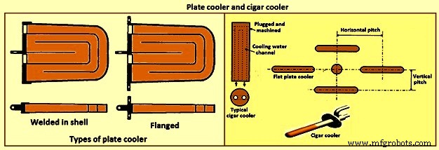
Fig 11 Plate cooler and cigar cooler
Cigar type (cylindrical) coolers (Fig 11) of steel and /or copper have also been successfully used. The philosophy of dense plate cooling (i.e. vertical pitch of 350 mm to 400 mm centre-to- centre, and horizontal pitch of 600 mm (centre-to-centre) has improved the cooling effect and increased lining life.
Copper cooling plates have traditionally been anchored in the shell plate with retainer bars or bolted connections to permit ready replacement if plate leakage occurs. More recently, plates have been designed with steel sections at the rear of the plate for welding directly to the steel shell. While sometimes taking longer to replace, this type provides a positive seal against BF gas leakage. Plate coolers are typically installed in areas above where the liquid iron collects in the furnace. Hence the mid-point of the tuyere breast, right up to the underside of the throat armour is the range of application.
Stave cooling – Cast iron cooling elements (Shannon plates or staves) have been used for several years in the bosh and hearth wall areas. These castings have cored cooling passages of large cross-section. While their service life have been not remarkable in the bosh, multiple campaigns have been normal for the hearth wall. These staves frequently suffered from low flow rates of marginal quality cooling water (scaling and debris deposition / build-up) and sometimes casting porosity. Water leaks into the hearth wall can be a considerable problem.
In the 1950s, the then USSR developed a new type of stave cooler (Fig 12) and ‘natural evaporative stave cooling’. For this design, castings were of gray cast iron containing steel pipes for water passes. The pipes were coated prior to casting to prevent carburization of the cooling pipe and metallurgical contact with the stave body material. The staves were installed in horizontal rows with the furnace and the cooling pipes projected through the shell. Vertical column of staves were formed by the inter-connection of the projecting pipes from one stave up to the corresponding stave in the next row. Staves can be applied to all the walls in the zones below the armour. Staves in the hearth wall and tuyere breast are supplied with smooth faces. Staves in the bosh, mantle / belly and stack normally have rib recesses for the installation of refractory.
Evolution of the stave cooler design has been dramatic. Staves in the higher heat load areas are now typically cast from ductile iron for improved thermal conductivity and crack resistance. While early stave design used castable refractory (installed after stave installation within the furnace), ribs now normally incorporate refractory bricks, either cast in place (with the stave body at the foundry) or slid and mortared in place prior to installation in the furnace. Fig 12 shows stave cooler and generations of stave development.
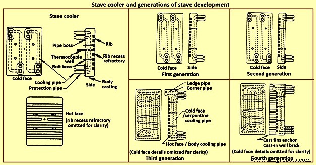
Fig 12 Stave cooler and generations of stave development
Staves are normally expected to retain a refractory lining in front for some time. After loss (expected) of the lining the staves are designed to resist the abrasive effects of descending burden and ascending dirty gas. As well, they are to absorb the expected process heat load and resist thermal load cycling and shock. Four generations of staves (Fig 12) are normally recognized in the industry.
First generation staves are no longer normally used. These staves have four cooling body circuits (with long radius bends which do not effectively cool the stave comers. These staves are made of gray iron castings with castable rib refractory. Second generation staves have four cooling body circuits with short radius bends for improved comer cooling. These staves are made of ductile iron castings with cast-in or glued-in rib bricks. Third generation staves have two-layer body cooling incorporating four or six cooling body circuits (stave hot face) and one or two serpentine cold face circuits (stave cold face) for additional or back-up cooling in the event of hot face circuit loss. These staves have additional edge cooling (top and bottom). The more frequent use of these staves is as cooled ledges to support a refractory lining. These staves have cast-in or mortared-in rib bricks. Fourth generation staves have two-layer cooling (similar to third generation). These staves have cooled ledges and cast-in wall brick lining eliminating the need for a manually placed interior brick lining.
Staves incorporating hot face ledges are more effective in retaining a brick lining than the smoother rib faced bricks. However, once the brick lining disappears, the ledges are very exposed within the furnace. The ledges disrupt burden descent and gas ascent. Exposed ledges tend to fail quickly. They are frequently serviced by cooling water separate from the main stave cooling circuit(s). In this way leaking ledge circuits can be more easily located or isolated. Some stave manufacturers are now providing separate ledge castings so that ledge cracking and loss does not damage the parent staves. As well, there is some present change in philosophy to abandon the application of ledges entirely.
Variations of the basic stave generation types are common. For example, staves of fourth generation type utilizing a refractory castable for the wall ling have been employed successfully. Alternatively, brick linings have been anchored to the stave bodies. Such approaches can be used to substitute for brick support ledges.
A ‘fifth’ generation of staves design has been the developed. It is the copper stave (Fig 13). The development of copper staves was carried out both in Japan and Germany for use in the region of bosh, belly, and lower stack to cope with high heat loads and large fluctuations of temperatures. While Japan has gone for cast copper staves, German copper staves are rolled copper plates having close outer tolerarnces and with drilling done for cooling passages. Drilled and plugged copper staves are typically designed for four water pipes in a straight line at the top and four water pipes in a stright line at the bottom. Materials for internal pipe coils include monel, copper, or steel. Unlike cast iron staves, copper staves are intended to be bonded to the cooling pipe.
The development of the cast-in copper stave has considered the following aspects. As per the first aspect, for the prevention of deformation, appropriate design of the stave length and bolt constrained points is important. The first aspect is that the use of the cast-in steel pipe copper stave with its own design is beneficial for effectively reducing the risk of deformation. Fig 13 shows the constrained points of a rolled copper stave and the cast-in steel pipe copper stave. A rolled copper stave is constrained to the shell by mounting bolts and pins. To prevent the weld at the base of a rising pipe from being damaged by stresses, rising piping is connected to the shell by an expansion joint. Due to this structure, the upper and lower ends of the staves are freely displaced, causing the staves to be easily deformed. The large thermal load which is repeatedly applied to the copper stave in the course of the fluctuation in the BF operations etc., causes plastic strain to be gradually accumulated, and results in large deformation. There are cases in which the deformation at the upper end has reached 50 mm or more and a weld has been broken, under the condition of an overly long stave, an in-appropriate bolt position, or high heat load exceeding the design condition.
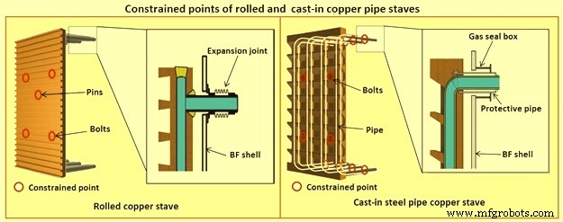
Fig 13 Constrained points of rolled and the cast-in pipe copper stave
Presently, the most popular type of copper stave is the rolled copper stave, the manufacturing process of which involves drilling holes on a copper plate. The water channel ends of these staves are plug-welded. The cast-in steel pipe copper stave, which has been developed, is made by casting bent steel pipes into the copper, a completely different manufacturing process from that of the conventional rolled copper stave. This unique manufacturing method has enabled achieving high energy efficiency and long life of BFs, which cannot be achieved using the rolled copper stave.
Natural evaporative stave cooling (NEVC) is a technique where boiler quality water is introduced into the bottom row of staves and flows by natural mean up the vertical cooling circuits. As the process heat conducts through the stave and cooling pipe into the water, the water in turn heats up. As the water warms, it expands. Since cooler water is being introduced below, the warm water tends to move upwards. At some point in the vertical cooling circuit, the water is at the boiling point. As the water changes its phase to steam, due to the latent heat of vapourization, additional heat is absorbed (driving the phase change). After boiling begins, two-phase flow (water and steam mixture) ascends the cooling pipes to the top of the furnace. Normally located on the furnace top platform are steam separator drums used to extract and vent the steam to atmosphere. Make-up water is introduced to the drum (to replace the discharged steam). The water is piped back by gravity to the furnace bottom and is fed once more to the staves. This cooling technique is very efficient and has low operating costs. There is no pumping equipment. The improvements in this system has been to boost the flow of the cooling water with recirculating pumps (forced evaporative cooling, FEVC) in order to ensure uniform cooling water flow and to cool the recirculating water (forced cold water cooling – FCWC). Both of these approaches have resulted in improved stave and lining life.
Staves provide an excellent protection for the shell plate throughout their service life (which is extended while the interior brick lining remains in place). Stave application has been implemented in all areas of the furnace from hearth wall up to and including the upper stack.
One drawback for conversion of an existing plate cooled furnace to stave cooling can be the cost of a new shell. However, if the existing shell is already in distress and is to be replaced in any event, the conversion cost is not a major factor.
Cast house
The cast house (Fig 14) is the area or areas at the BF where equipment is placed to safely extract the hot metal and liquid slag from the furnace, separate them, and direct them to the appropriate handling equipment or facilities. The hot metal and liquid slag are removed from the furnace through the tap hole. Only infrequently today slag is flushed from the slag notch. The equipment for tap hole is to be reliable and need minimum maintenance. Furnaces typically tap eight times to eleven times per day.
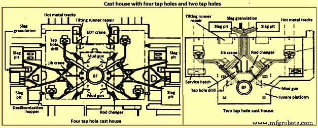
Fig 14 Cast house with four tap holes and two tap holes
Mud gun – The mud gun is used to close the tap hole after tapping is complete. A quantity of the tap hole mass is pushed by the mud gun to fill the worn hole and to maintain a quantity of the tap hole mass (the mushroom) within the hearth. The mud gun is normally held in place on the tap hole until the tap hole mass cures and the tap hole is securely plugged. A hydraulic mud gun uses hydraulic power to swing, hold, and push the tap hole mass. Typical injection pressure of tap hole mass is of the order of 20 MPa to 25 MPa, permitting it to push viscous mass into the furnace operating at high pressures. The hydraulic gun is held against the furnace with the equivalent of 15 tons to 35 tons of force. This type of mud gun can be swung into place in one motion.
An electro-mechanical gun has three separate electric drives for unit swing, barrel positioning, and ramming. Hence several separate motions are needed for accurate positioning of the mud gun at the tap hole. Tap hole mass injection pressure is in the range of only 5 MPa to 8 MPa. The electro-mechanical mud gun is latched to the furnace to keep it in place during plugging.
Tap hole drill – Tap hole drill is used to bore a hole though the tap hole clay into the hearth of the furnace. A drill unit is swung into place hydraulically and held hydraulically in the working position. A pneumatic motor feeds the hammer drill unit (with an attached drill rod and bit) into the hole. Compressed air is fed down the centre of the drill rod and the drill bit to cool the bit and blowout the removed tap hole mass. When the tap hole drill rod has penetrated into the hearth, the drill rod is retracted and the drill swings clear of the hot metal stream.
Soaking bar technique – The application of the soaking bar practice has improved the tapping process. When the tap hole mass is still pliable after plugging, a steel bar is driven into the tap hole by the tap hole drill. While the bar sits in place during the time between casts, it heats up by conduction from the hearth hot metal. This permits curing of the tap hole mass along its entire length (as opposed to curing with the furnace and setting at the outside near the furnace cooling elements). The cured tap hole mass is more resistant to erosion during tapping, hence improving tap flow rate control. Less tap hole mass is needed to replug the hole. When the tap hole is to be opened, a clamping device and a back hammering device on the tap hole drill extract the rod. The timing for tap hole opening can be more easily controlled (predicted) than by conventional drilling. This feature is important for smooth furnace operation and for scheduling of hot metal delivery to downstream facilities.
Same side tap hole equipment – Mud gun and drills have normally been installed on opposite sides of the tap hole. Design development has permitted installation of these equipments on one side of the tap hole. The drill swings over the mud gun or vice versa. This type of installation facilitates improved access for tap hole and trough maintenance and the improved application of trough and tap hole area flue collection.
With the advent of tuyere access platforms to facilitate tuyere and tuyere stock inspection and replacement, the headroom available for the tap hole equipment has diminished. However, same side tap hole equipment installations can be achieved with low headroom (for example 2.2 metres).
Trough and runner system – Typical hot metal and slag tapping rates are in the range of 4 to 6 tons per minute and 3 to 5 tons per minute, respectively. The trough and runner systems are to be designed to properly separate the iron and slag and to convey them away from the furnace for flow rates within the normal flow rate range and for unusual peak flow rates.
The hot metal trough (Fig 15) is a refractory lined tundish located in the cast house floor and designed to collect iron and slag after discharge from the furnace. The hot metal flows down the trough, under a skimmer and over a dam into the hot metal runner system. The hot metal level in the trough is dictated by the dam. Proper dam design submerges the lowest portion of the skimmer in the hot metal pool. The slag, being lighter than the hot metal, floats down the trough on top of the hot metal pool. Since it cannot sink into the hot metal and through the skimmer opening, it pools on top of the hot metal until sufficient volume collects to overflow a slag dam and run down the slag runner. At the end of the tapping, the slag runner dam height is lowered to drain off most of the slag. The residual hot metal is retained in the trough to prevent oxidation and thermal shock of the trough refractory lining.
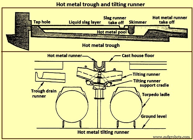
Fig 15 Hot metal trough and tilting runner
When maintenance of the trough lining is needed, the hot metal pool can be dumped by removing the hot metal dam, or by opening a trough drain gate, or by drilling into the side of the trough (at its lowest point) with a drain drill. The trough bottom is normally designed with a 2 % (minimum) slope for effective draining. Trough cross-section and length design are important for effective iron and slag flow pattern, retention, and separation. A good trough design results in hot metal yield improvements. Effective trough lining and cooling techniques are important for lining life, hot metal temperature, and cast house structural steel and concrete heat protection considerations. Troughs traditionally were contained in steel boxes ‘buried in sand’ in the cast house floor system. Improved trough design incorporates forced or natural air convection or water-cooling.
Cast house practice needs the runners to be as short as possible. This minimizes temperature loss of hot metal and reduces runner maintenance and flue generation. Shorter runners can also result in reduced capital expenditure for cast house building installation or modification. Since the runners are to slope away from the furnace, the cast house floor normally follows the same slope as the runners.
Slag runners are normally designed with a 7 % (minimum) slope. Slag can be directed to (i) slag pots for railway or mobile equipment haulage to a remote site for dumping, (ii) slag pits adjacent to the furnace for air cooling and water quenching prior to excavation by mobile equipment, and (iii) granulation facilities adjacent to the furnace for conversion of the liquid slag to granulated slag. Granulation units are provided with systems to eliminate flue emissions associated with environmental issues.
Hot metal runners are normally designed with a 3 % (minimum) slope. Hot metal is normally directed to hot metal transfer ladles (torpedo cars / open top ladles) for movement to the steel melting shop or pig casting machines. While normal practice used is to have one iron runner system with diverter gates directing the hot metal to different pouring positions, each with a ladle. Application of the tilting runner practice has been beneficial. A tilting runner is normally with an electrical motor-driven actuator (with a manual hand wheel back-up), and is tilted at around 5 degrees to divert the hot metal. A pool of hot metal is held in the tilting runner to minimize splashing and refractory wear. When one hot metal ladle has been filled, the runner is tilted to the opposite side to fill the other ladle. If needed, a locomotive removes the filled ladle and spots an empty ladle in its place. This operation can be done without plugging the furnace. When the tapping is finished, the tilting runner is tilted an additional 5 degrees to dump its pool of hot metal into the ladle.
Modern cast house design includes flat floors, where the runner is fully covered and is fitted flush with the floor. This allows safer and easier use of mobile vehicles in the cast house area. The use of radio controlled equipment and other devices have helped to reform cast house work, and these, along with effective emission control systems, have improved working conditions. As the BF hearth diameter is increased, there is a resulting need to increase the size of the cast-house. Large BF are normally designed with four tap holes (Fig 14). With a four top-hole configuration, the cast-house arrangement needs to provide sufficient space for movement around the floor itself. There is no design issues associated with this requirement as long as there is the necessary space provided in the site plan. Increasing the size of the cast-house in terms of floor plan does not represent a radical change in design philosophy which can pose a challenge the furnace designer. An efficient and strictly controlled tapping is necessary for ensuring a stable operation and high productivity of the BF.
Emission control
Fume collection requirements and applications appear to vary considerably around the globe. BFs presently have full, partial, or even no cast house fume collection system. Exhaust fan and bag house capacity of the order of 9,000 cubic meter per minute (cum/min) to 11,500 cum/min (depending upon operation and design practices) is typical for full flue capture of a two tap hole cast house installation (for trough runners and tilting runners).
Proper design and application of flue collection runner covers can facilitate cast house access (i.e. flat floor configuration using steel slabs or plates) for personnel and mobile equipment crossover. Runner covers can also reduce hot metal temperature loss and improve runner refractory longevity.
Some furnaces use flame suppression which eliminates the oxygen in the air directly over the trough and iron runners. Products of combustion prevent oxidation of the hot metal surface reducing visible particulate and flues.
Other aspects of BF design
It is necessary that complete study of every element in the process chain, from raw materials delivery to hot metal consumption is made to ensure that there are no ‘bottle necks’ in the system which can prevent the furnace from meeting the goals of its installation. While designing the BF, thought process is to be used to develop the furnace design and some alternatives are to be considered before freezing the design. During the designing of the furnace, those furnace equipments are to be selected which best meet the needs of the furnace operation.
The furnace design is to ensure (i) the furnace is capable of meeting the operational goals of production, productivity (tons per day per cubic metre of working volume), specific consumptions (kilograms per ton of hot metal), and product quality in cost effective manner, (ii) the furnace has the flexibility to accept and absorb the changes in the quality of the raw materials, and (iii) the furnace is capable of achieving the desired campaign life both with respect to time and the total production.
Financial justification is the over-riding consideration for the design. For this purpose, the economic study is to be very extensive. Further, the furnace design is to include latest technological developments so that the furnace does not become technologically outdated during its entire campaign.
The working volume of the furnace is the internal volume of the furnace calculated between the tuyeres and the stock line. Hearth productivity of the furnace is rated in tons per day per cubic metre of active hearth volume. Active hearth volume is the internal volume of the furnace calculated between the tuyeres and the tap hole. Active hearth volume is a measure of the holding capacity of the furnace for the liquids produced in the working volume (above the tuyeres). Hence, the tons per day per cubic metre of active hearth volume is a measure of the specific capacity (through-put per unit volume) of the hearth of the BF.
The design of the hearth is very important since it has a strong effect on the furnace operation. The furnace operation gets affected since the hearth liquid levels change rapidly which cause variations in gas flow pattern, gas utilization, and blast pressure. Also, because of these rapid changes in liquid level, there can be jamming / burning of the tuyeres which affect the blowing of the furnace.
The furnace hearth volume also determines the controls the operator is to exercise during furnace operation. For a very good hearth liquid level control, the high through-put furnace need around 90 % time spent in tapping. To make this time of tapping possible, cast floor is to be designed properly.
The furnace lining and cooling system needs special attention so that it does not pose any problem during the entire campaign of the BF. The selection of refractories, cooling elements, and internal furnace geometry is very important in this respect. Copper staves in this respect are expensive but they are very economical in comparison to the alternatives. Carbon lining of the hearth is very important for the long life of the hearth. The refractory lining thickness of the stack has implication on the furnace working volume.
The production needed normally determines the size of the BF. However, for the sizing of the BF, the raw materials, the product chemistry, and even operating philosophy are important. While the furnace size has implication on the capital cost, the productivity improvement has implication on the operating cost. The specific productivity of the furnace is to be determined for the determination of the size of the BF needed to produce the required quantity of hot metal. From the wide range of possible operating rates, the working volume of the furnace is to be calculated. Productivity and hence the furnace size is also to be based on the fuel rate. The fuel rate is dependent on the quality of raw materials, hot blast parameters, hot metal quality, and the operating philosophy.
The size is the most important factor for the determination of the BF productivity. However, there are other factors which also influence the BF productivity. The most important of these factors include (i) hot blast temperature and pressure, (ii) high top pressure, (iii) oxygen enrichment of the air blast, (iv) injection of auxiliary fuel at the tuyere, (v) prepared burden (sinter, pellets etc.), (vi) Fe content of the ferrous burden, (vii) ash in coke, (viii) quality of the coke, (ix) moisture content of the burden, (x) direct charging of fluxes (lime stone, dolomite etc.) in the BF, (xi) content of fines in the burden, (xii) quality of hot metal to be produced, (xiii) burden distribution control in the furnace, and (xiv) level of automation and control in the furnace.
The availability of furnace equipment, provision of stand-by equipment, and the maintenance philosophy are important factors which have high influence on the annual production from the BF. Further, incorporation of safe and healthy working practices during the operation of BF in the design of the BF is important which has a high influence on the furnace productions. In this regards, safety interlocks are to be provided at all the places where there exist a chance of unsafe operating practices to take place.
Proceso de manufactura
- La escoria de alto horno y su papel en la operación del horno
- Aspectos importantes del diseño de Altos Hornos y equipos auxiliares asociados
- Sistema de control, medición y automatización de procesos de alto horno
- Generación y uso de gas de alto horno
- Productividad del alto horno y los parámetros que influyen
- Operación de alto horno y escoria con alto contenido de alúmina
- Sistema de enfriamiento de alto horno
- Casa de Fundición de Alto Horno y su Operación
- Alto Horno y su Diseño
- Prácticas de operación y vida de campaña de un alto horno
- Fabricación de hierro por alto horno y emisiones de dióxido de carbono