Lógica combinacional con asignación
La declaración de asignación de verilog generalmente se usa para impulsar continuamente una señal de wire tipo de datos y se sintetiza como lógica combinacional. Aquí hay algunos ejemplos de diseño más usando el assign declaración.
Ejemplo #1:lógica combinacional simple
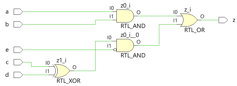
El código que se muestra a continuación implementa una lógica combinacional digital simple que tiene un cable de salida z que se activa continuamente con un assign declaración para realizar la ecuación digital.
module combo ( 	input 	a, b, c, d, e,
								output 	z);

	assign z = ((a & b) | (c ^ d) & ~e);

endmodule
El módulo combo se elabora en el siguiente esquema de hardware utilizando herramientas de síntesis y se puede ver que la lógica combinacional se implementa con puertas digitales.
Banco de pruebas
El banco de pruebas es una plataforma para simular el diseño para garantizar que el diseño se comporte como se esperaba. Todas las combinaciones de entradas se conducen al módulo de diseño usando un for bucle con una declaración de retraso de 10 unidades de tiempo para que el nuevo valor se aplique a las entradas después de algún tiempo.
module tb;
	// Declare testbench variables
  reg a, b, c, d, e;
  wire z;
  integer i;

  // Instantiate the design and connect design inputs/outputs with
  // testbench variables
  combo u0 ( .a(a), .b(b), .c(c), .d(d), .e(e), .z(z));

  initial begin
  	// At the beginning of time, initialize all inputs of the design
  	// to a known value, in this case we have chosen it to be 0.
    a <= 0;
    b <= 0;
    c <= 0;
    d <= 0;
    e <= 0;

    // Use a $monitor task to print any change in the signal to
    // simulation console
    $monitor ("a=%0b b=%0b c=%0b d=%0b e=%0b z=%0b",
              a, b, c, d, e, z);

    // Because there are 5 inputs, there can be 32 different input combinations
    // So use an iterator "i" to increment from 0 to 32 and assign the value
    // to testbench variables so that it drives the design inputs
    for (i = 0; i < 32; i = i + 1) begin
      {a, b, c, d, e} = i;
      #10;
    end
  end
endmodule
Registro de simulación ncsim> run a=0 b=0 c=0 d=0 e=0 z=0 a=0 b=0 c=0 d=0 e=1 z=0 a=0 b=0 c=0 d=1 e=0 z=1 a=0 b=0 c=0 d=1 e=1 z=0 a=0 b=0 c=1 d=0 e=0 z=1 a=0 b=0 c=1 d=0 e=1 z=0 a=0 b=0 c=1 d=1 e=0 z=0 a=0 b=0 c=1 d=1 e=1 z=0 a=0 b=1 c=0 d=0 e=0 z=0 a=0 b=1 c=0 d=0 e=1 z=0 a=0 b=1 c=0 d=1 e=0 z=1 a=0 b=1 c=0 d=1 e=1 z=0 a=0 b=1 c=1 d=0 e=0 z=1 a=0 b=1 c=1 d=0 e=1 z=0 a=0 b=1 c=1 d=1 e=0 z=0 a=0 b=1 c=1 d=1 e=1 z=0 a=1 b=0 c=0 d=0 e=0 z=0 a=1 b=0 c=0 d=0 e=1 z=0 a=1 b=0 c=0 d=1 e=0 z=1 a=1 b=0 c=0 d=1 e=1 z=0 a=1 b=0 c=1 d=0 e=0 z=1 a=1 b=0 c=1 d=0 e=1 z=0 a=1 b=0 c=1 d=1 e=0 z=0 a=1 b=0 c=1 d=1 e=1 z=0 a=1 b=1 c=0 d=0 e=0 z=1 a=1 b=1 c=0 d=0 e=1 z=1 a=1 b=1 c=0 d=1 e=0 z=1 a=1 b=1 c=0 d=1 e=1 z=1 a=1 b=1 c=1 d=0 e=0 z=1 a=1 b=1 c=1 d=0 e=1 z=1 a=1 b=1 c=1 d=1 e=0 z=1 a=1 b=1 c=1 d=1 e=1 z=1 ncsim: *W,RNQUIE: Simulation is complete.

Ejemplo #2:Medio sumador
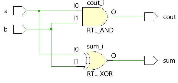
El módulo de medio sumador acepta dos entradas escalares a y b y usa lógica combinacional para asignar la suma de las salidas y el bit de acarreo cout. La suma se obtiene mediante un XOR entre a y b, mientras que el bit de acarreo se obtiene mediante un AND entre las dos entradas.
module ha ( input 	a, b,
						output	sum, cout);

	assign sum  = a ^ b;
	assign cout = a & b;
endmodule
Banco de pruebas
module tb;
	// Declare testbench variables
  reg a, b;
  wire sum, cout;
  integer i;

  // Instantiate the design and connect design inputs/outputs with
  // testbench variables
  ha u0 ( .a(a), .b(b), .sum(sum), .cout(cout));

  initial begin
  	// At the beginning of time, initialize all inputs of the design
  	// to a known value, in this case we have chosen it to be 0.
    a <= 0;
    b <= 0;

    // Use a $monitor task to print any change in the signal to
    // simulation console
    $monitor("a=%0b b=%0b sum=%0b cout=%0b", a, b, sum, cout);

    // Because there are only 2 inputs, there can be 4 different input combinations
    // So use an iterator "i" to increment from 0 to 4 and assign the value
    // to testbench variables so that it drives the design inputs
    for (i = 0; i < 4; i = i + 1) begin
      {a, b} = i;
      #10;
    end
  end
endmodule
Registro de simulación ncsim> run a=0 b=0 sum=0 cout=0 a=0 b=1 sum=1 cout=0 a=1 b=0 sum=1 cout=0 a=1 b=1 sum=0 cout=1 ncsim: *W,RNQUIE: Simulation is complete.

Ejemplo #3:sumador completo
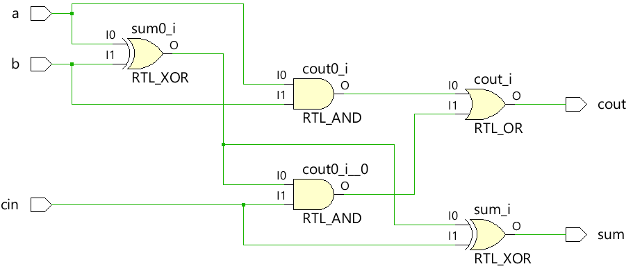
Se puede construir un sumador completo usando el módulo de medio sumador que se muestra arriba o se puede aplicar toda la lógica combinacional tal como está con assign instrucciones para controlar las salidas sum y cout.
module fa (	input 	a, b, cin,
						output 	sum, cout);

	assign sum  = (a ^ b) ^ cin;
	assign cout = (a & b) | ((a ^ b) & cin);
endmodule
Banco de pruebas
module tb;
  reg a, b, cin;
  wire sum, cout;
  integer i;

  fa u0 ( .a(a), .b(b), .cin(cin), .sum(sum), .cout(cout));

  initial begin
    a <= 0;
    b <= 0;

    $monitor("a=%0b b=%0b cin=%0b sum=%0b cout=%0b", a, b, cin, sum, cout);

    for (i = 0; i < 7; i = i + 1) begin
      {a, b, cin} = i;
      #10;
    end
  end
endmodule
Registro de simulación ncsim> run a=0 b=0 cin=0 sum=0 cout=0 a=0 b=0 cin=1 sum=1 cout=0 a=0 b=1 cin=0 sum=1 cout=0 a=0 b=1 cin=1 sum=0 cout=1 a=1 b=0 cin=0 sum=1 cout=0 a=1 b=0 cin=1 sum=0 cout=1 a=1 b=1 cin=0 sum=0 cout=1 ncsim: *W,RNQUIE: Simulation is complete.

Ejemplo #4:Multiplexor 2x1
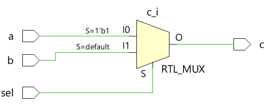
El multiplexor simple 2x1 usa un operador ternario para decidir qué entrada debe asignarse a la salida c. Si sel es 1, la salida es impulsada por a y si sel es 0, la salida es impulsada por b.
module mux_2x1 (input 	a, b, sel,
								output 	c);

	assign c = sel ? a : b;
endmodule
Banco de pruebas
module tb;
	// Declare testbench variables
  reg a, b, sel;
  wire c;
  integer i;

  // Instantiate the design and connect design inputs/outputs with
  // testbench variables
  mux_2x1 u0 ( .a(a), .b(b), .sel(sel), .c(c));

  initial begin
  	// At the beginning of time, initialize all inputs of the design
  	// to a known value, in this case we have chosen it to be 0.
    a <= 0;
    b <= 0;
    sel <= 0;

    $monitor("a=%0b b=%0b sel=%0b c=%0b", a, b, sel, c);

    for (i = 0; i < 3; i = i + 1) begin
      {a, b, sel} = i;
      #10;
    end
  end
endmodule
Registro de simulación ncsim> run a=0 b=0 sel=0 c=0 a=0 b=0 sel=1 c=0 a=0 b=1 sel=0 c=1 ncsim: *W,RNQUIE: Simulation is complete.

Ejemplo #5:Demultiplexor 1x4
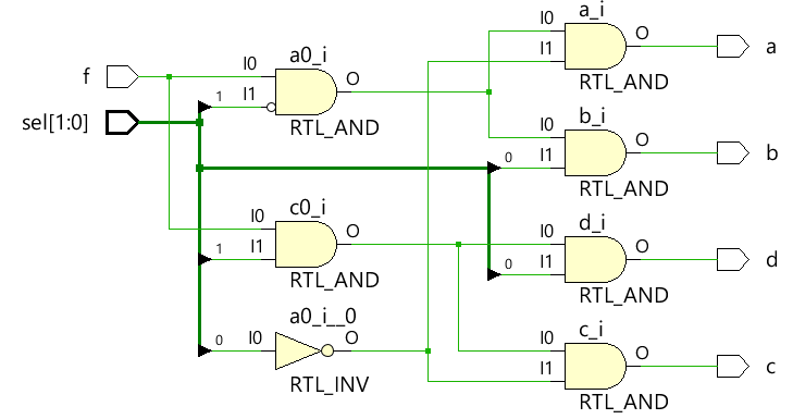
El demultiplexor usa una combinación de entradas sel y f para controlar las diferentes señales de salida. Cada señal de salida es impulsada por un assign separado declaración. Tenga en cuenta que generalmente no se recomienda que la misma señal sea impulsada por diferentes assign declaraciones.
module demux_1x4 (	input 				f,
										input [1:0]	 	sel,
										output 				a, b, c, d);

	assign a = f & ~sel[1] & ~sel[0];
	assign b = f &  sel[1] & ~sel[0];
	assign c = f & ~sel[1] &  sel[0];
	assign d = f &  sel[1] &  sel[0];

endmodule
Banco de pruebas
module tb;
	// Declare testbench variables
  reg f;
  reg [1:0] sel;
  wire a, b, c, d;
  integer i;

  // Instantiate the design and connect design inputs/outputs with
  // testbench variables
  demux_1x4 u0 ( .f(f), .sel(sel), .a(a), .b(b), .c(c), .d(d));

  // At the beginning of time, initialize all inputs of the design
  // to a known value, in this case we have chosen it to be 0.
  initial begin
    f <= 0;
    sel <= 0;

    $monitor("f=%0b sel=%0b a=%0b b=%0b c=%0b d=%0b", f, sel, a, b, c, d);

    // Because there are 3 inputs, there can be 8 different input combinations
    // So use an iterator "i" to increment from 0 to 8 and assign the value
    // to testbench variables so that it drives the design inputs
    for (i = 0; i < 8; i = i + 1) begin
      {f, sel} = i;
      #10;
    end
  end
endmodule
Registro de simulación ncsim> run f=0 sel=0 a=0 b=0 c=0 d=0 f=0 sel=1 a=0 b=0 c=0 d=0 f=0 sel=10 a=0 b=0 c=0 d=0 f=0 sel=11 a=0 b=0 c=0 d=0 f=1 sel=0 a=1 b=0 c=0 d=0 f=1 sel=1 a=0 b=0 c=1 d=0 f=1 sel=10 a=0 b=1 c=0 d=0 f=1 sel=11 a=0 b=0 c=0 d=1 ncsim: *W,RNQUIE: Simulation is complete.

Ejemplo #6:Decodificador 4x16
module dec_3x8 ( 	input 					en,
									input 	[3:0] 	in,
									output  [15:0] 	out);

	assign out = en ? 1 << in: 0;
endmodule

Banco de pruebas
module tb;
  reg en;
  reg [3:0] in;
  wire [15:0] out;
  integer i;

  dec_3x8 u0 ( .en(en), .in(in), .out(out));

  initial begin
    en <= 0;
    in <= 0;

    $monitor("en=%0b in=0x%0h out=0x%0h", en, in, out);

    for (i = 0; i < 32; i = i + 1) begin
      {en, in} = i;
      #10;
    end
  end
endmodule
Registro de simulación ncsim> run en=0 in=0x0 out=0x0 en=0 in=0x1 out=0x0 en=0 in=0x2 out=0x0 en=0 in=0x3 out=0x0 en=0 in=0x4 out=0x0 en=0 in=0x5 out=0x0 en=0 in=0x6 out=0x0 en=0 in=0x7 out=0x0 en=0 in=0x8 out=0x0 en=0 in=0x9 out=0x0 en=0 in=0xa out=0x0 en=0 in=0xb out=0x0 en=0 in=0xc out=0x0 en=0 in=0xd out=0x0 en=0 in=0xe out=0x0 en=0 in=0xf out=0x0 en=1 in=0x0 out=0x1 en=1 in=0x1 out=0x2 en=1 in=0x2 out=0x4 en=1 in=0x3 out=0x8 en=1 in=0x4 out=0x10 en=1 in=0x5 out=0x20 en=1 in=0x6 out=0x40 en=1 in=0x7 out=0x80 en=1 in=0x8 out=0x100 en=1 in=0x9 out=0x200 en=1 in=0xa out=0x400 en=1 in=0xb out=0x800 en=1 in=0xc out=0x1000 en=1 in=0xd out=0x2000 en=1 in=0xe out=0x4000 en=1 in=0xf out=0x8000 ncsim: *W,RNQUIE: Simulation is complete.

Verilog
- Tutorial - Escritura de código combinacional y secuencial
- Circuito con un interruptor
- Circuitos integrados
- Controladores lógicos programables (PLC)
- Introducción al álgebra booleana
- Simplificación lógica con mapas de Karnaugh
- Aritmética con notación científica
- Preguntas y respuestas con un arquitecto de soluciones de Industria 4.0
- Supervisión de la temperatura con Raspberry Pi
- Ejemplos de nivel de puerta de Verilog
- Formato de hora de Verilog


