Jukebox moderno
Componentes y suministros
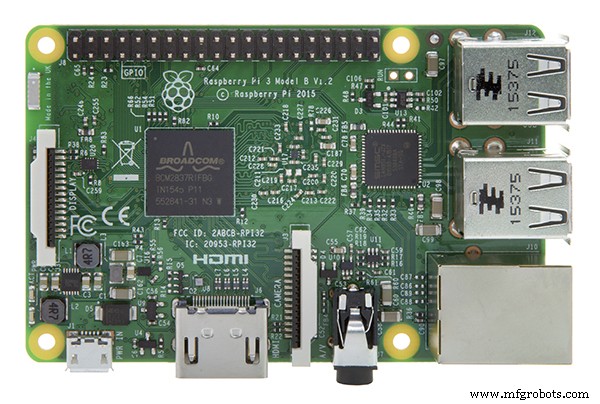 |
| × | 1 | |||
| × | 1 | ||||
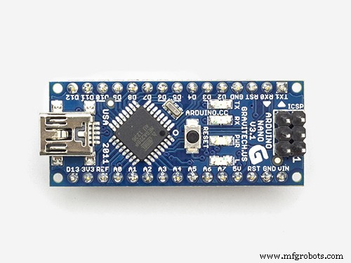 |
| × | 1 | |||
 |
| × | 1 | |||
| × | 1 | ||||
| × | 1 | ||||
| × | 1 | ||||
| × | 1 | ||||
| × | 1 | ||||
 |
| × | 1 | |||
| × | 1 | ||||
 |
| × | 2 | |||
 |
| × | 1 | |||
| × | 2 | ||||
| × | 1 | ||||
| × | 1 | ||||
| × | 1 | ||||
| × | 1 | ||||
 |
| × | 1 | |||
| × | 4 | ||||
| × | 8 | ||||
 |
| × | 4 | |||
| × | 1 | ||||
| × | 1 | ||||
| × | 1 | ||||
| × | 1 | ||||
| × | 1 | ||||
| × | 1 | ||||
| × | 1 | ||||
 |
| × | 12 | |||
| × | 1 | ||||
| × | 1 | ||||
| × | 1 | ||||
| × | 1 | ||||
 |
| × | 7 |
Herramientas y máquinas necesarias
 |
| |||
 |
| |||
 |
| |||
|
Aplicaciones y servicios en línea
| ||||
 |
| |||
|
Acerca de este proyecto
Actualización:como se ve en The MagPi Magazine, número 105
Inspiración
He estado enamorado de las máquinas de discos clásicas durante años. Ya en 2014, estaba tratando de hacer uno, pero no tenía las habilidades para una construcción atractiva. Avance rápido hasta hoy, cuando aprendí algunas habilidades de diseño e impresión 3D.
La pasión, la curiosidad y el deseo impulsaron este esfuerzo. Si está pensando que le gustaría tener una mini máquina de discos como esta, hay ofertas de mercado masivo que son mucho más barato como este modelo de mesa de Victrola por $ 65 USD. Flyingangel, el fabricante de hacksters, tiene una gran estructura de máquina de discos. Por otro lado, hay máquinas de discos modernas listas para usar que son más grandes (105 cm / 41,3 pulgadas de alto) pero mucho más caras, alrededor de $ 795 USD. Verifique el costo y Esfuerzo secciones a continuación para ver cuánto está involucrado en este proyecto.
Atribución
Este proyecto no hubiera sido posible sin el excelente diseño de jukebox 3D de Marco Gregorio en grabcad. Es un trabajo maravillosamente detallado, hecho aún más sorprendente ya que Marco no tenía una máquina de discos física para modelar, ¡solo lo que podía encontrar en Internet! Te debes a ti mismo comprobar el trabajo de Marco ...
También es esencial para la máquina de discos el código Arduino utilizado para hacer que los LED se iluminen con música, por Michael Bartlett en learn.sparkfun.com.
Descripción general
Este es un reproductor de música que funciona con el software gratuito Volumio. Volumio cuenta con AirPlay, Spotify, Pandora, radio web y su propia música controlada desde su computadora, tableta o teléfono, solo descargue e instale. ¿Qué agregué? Una carcasa 3D, una pantalla LCD táctil y LED que se iluminan con música. La pantalla LCD se alimenta desde una Raspberry Pi 3 o 4. Los LED están controlados por un Arduino Micro en una placa Adafruit Perma-Proto adjunta en la parte superior de una pila de hardware:Raspberry Pi y IQAudio Pi Digi Amp.
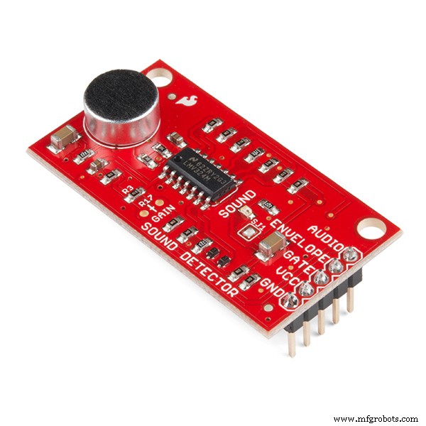
Estoy usando hardware antiguo, la placa de amplificador IQAudio y un Arduino Micro, que tenía en el inventario. Al momento de escribir estas líneas, IQAudio ahora es parte de Raspberry Pi, y el Pi Digi Amp Plus todavía está disponible, Y por menos de lo que pagué por él. El Arduino Micro está obsoleto, pero podría usar un Arduino Nano o Adafruit Itsy-Bitsy. Tendrá que hacer ajustes para el uso de pines analógicos y digitales y alimentar 5V de energía desde el Digi Amp a la placa secundaria (Arduino). Finalmente, un detector de sonido Sparkfun transforma mágicamente el sonido en bits digitales.
Marco proporcionó un archivo STEP para todos los componentes de la máquina de discos que pude importar a la aplicación de diseño Fusion 360 3D. Lo que hice fue:
- Escale el modelo al 25% del tamaño del modelo de tamaño completo de Marco
- Revise los componentes del modelo y decida qué conservar y qué agregar
- Escondí las partes del modelo que no usé
- Agregue y modifique funciones para crear un recinto útil
- Imprime los cuerpos 3D que forman el recinto
- Agregue componentes electrónicos para alimentar Volumio y los LED
Objetivos de diseño
- Tener una altura aproximada de 381 mm / 15 pulgadas
- Pantalla táctil que muestra Reproducción en curso / Carátula del álbum
- Altavoces que suenan decentes
- Luces ... Tenía que tener muchos LED animados encantadores
- En realidad, PAREJA se imprimió en 3D (sin posprocesamiento de la impresión); eso significaba imprimir en diferentes colores de filamentos
- No se permiten impresiones en 3D de más de 12 horas (no se permiten impresiones durante la noche)
- Ocultar o minimizar las juntas de las piezas
Nivel de habilidad:avanzado
- Más de 75 horas de tiempo total de impresión para piezas 3D
- Ensamblaje crítico:tienes que hacer las cosas "bien", hacer las cosas en un orden determinado
- Espacio confinado para trabajar dentro de la caja cuando haya terminado
Costo:caro
(Todos los costos en USD)
Como mínimo:
- Si realiza el posprocesamiento, necesitará de 2 a 3 bobinas de filamento 3D blanco y suministros de acabado, con un estimado de 70 a 90 dólares.
O
- Depende de lo que tengas. Solo tuve que comprar un carrete de filamento rojo, alrededor de $ 30. He estado imprimiendo en 3D desde 2017 y es un pasatiempo importante para mí. Tenía filamentos plateados, blancos, marrones y negros en inventario. Esos, más un carrete de rojo serían al menos alrededor de $ 100.
- Arduino Nano o Adafruit Mini Metro, alrededor de $ 20 (tenía Arduino Micro en el inventario)
- Sombrero Adafruit Raspberry Pi Perma Proto $ 5
- Pantalla táctil HDMI (Uctronics) de 5 pulgadas, $ 53
- Raspberry Pi 3B Plus $ 35 (disponible)
- Parts Express Dayton Audio RS100-8 Speakers, 2x $ 60 en total (en inventario)
- Parts Express Speaker Wire, 18AWG aproximadamente $ 20 (en inventario)
- Paño para rejilla de altavoz Parts Express, $ 30 (en inventario)
Calcule otros $ 40 o más para cables / conectores HDMI, interruptores, hardware de montaje, cables de puente, conector hembra, etc. Tenía mucho de eso en el inventario. Para mí, el costo actual de mi bolsillo era de aproximadamente $ 150, distribuidos en meses, porque tenía muchos suministros a mano. Si tuvieras que salir y comprar todos esos suministros ... Bueno, haz los cálculos.
Para mí, el costo valió la pena.
Esfuerzo
Las impresiones en 3D tardarán 75 horas o más, dependiendo de su impresora. Hay 21 partes diferentes con aproximadamente 12 que tardan varias horas en imprimirse. Las partes restantes tardan entre 1 y 2 horas cada una. Y eso suponiendo que no tenga impresiones para hacer otra vez.
Usé pegamento caliente para preparar y unir las secciones de la carcasa, en 4 fases. Suponga 3-4 horas. para eso. Pegar las cadenas de LED tarda aproximadamente una hora en configurarse y ejecutarse. También hay un pegado preciso de pequeñas piezas decorativas (con pegamento CA) para completar la máquina de discos.
Para la electrónica, calcule al menos 5 horas para:
- Instale Volumio
- Instale el boceto de Arduino
- Diseñe y suelde la placa de circuito
- ¡Pruebe que todo funcione antes del ensamblaje final!
- Monte el panel LCD
- Monte la placa RPi, IQAudio Digi Amp Plus y Perma Proto en una pila
- Soldar y montar los interruptores y el conector de alimentación
- Monte los altavoces y los cables de los altavoces
El pegado final puede tardar entre 1 y 2 horas.
En resumen, además del tiempo de impresión de todas las piezas, el montaje puede tardar unas 12 horas o más.
Descargas
La documentación, el código y los archivos de impresión 3D están disponibles en github.
Los archivos de impresión 3D también están disponibles en Thingiverse.
Impresión 3D
Hay un total de 21 archivos de piezas STL independientes. Algunas partes requerirán 2 copias / impresiones.
Comenzando
Asegúrese de leer los comentarios en las secciones "Cosas" con atención. Proporcionan la información necesaria sobre los componentes exactos que se deben utilizar. Si realiza sustituciones de piezas, tendrá que averiguar qué cambios deben realizarse.
Para asegurarse de que todo funcione, pruebe que todos los componentes electrónicos funcionen juntos antes de ensamblar la carcasa:
- Instale y configure Volumio
- Suelde la placa de circuito
- Conecte los componentes:NeoPixels, LED RGB de atenuación lenta e interruptores
- Agregue componentes a la placa
- Descargue el boceto de Arduino desde github
- Sube el boceto al Arduino, montado en la placa
- Pruébelo todo
Instalar Volumio
Vaya a la página de inicio de Volumio y siga la guía de configuración de su Raspberry Pi. Para comenzar a probar, monte el amplificador IQAudio Pi Digi en la Raspberry Pi, conecte el amplificador al conector hembra del Pi y use separadores del Pi al amplificador IQAudio como se muestra en la foto de abajo. Más adelante, consulte esta guía para montarlos en la parte inferior de la máquina de discos impresa en 3D.
_9H4kWWGtUT.jpeg?auto=compress%2Cformat&w=680&h=510&fit=max)
Conecte dos cables de puente hembra a macho a los terminales + 5V y GND del Digi Amp Plus, que se muestra en la foto a continuación. Estos se conectarán a la placa Perma-Proto para alimentar los NeoPixels directamente desde el Pi Digi Amp Plus.
El último modelo de Digi Amp tiene todos los pines del cabezal del Pi expuestos, por lo que los pines de 5V y GND estarán en la ubicación del pin del cabezal del Pi estándar.
_4dxCv32yCp.jpeg?auto=compress%2Cformat&w=680&h=510&fit=max)
Para configurar los altavoces, corte dos pares de cables de altavoz (14-26 AWG) de aproximadamente 7 pulgadas / 18 cm de largo y conéctelos a los terminales de altavoz y a los terminales de tornillo IQAudio. El Pi se alimentará desde IQAudio - NO conecte la alimentación al conector de alimentación Pi. Conecte un bloque de alimentación al IQaudio e intente reproducir una radio web de Volumio.
La galería a continuación muestra la configuración de Volumio para IQAudio Pi Digi Amp Plus y el complemento de pantalla táctil (Configuración / Complementos / Miscelánea):
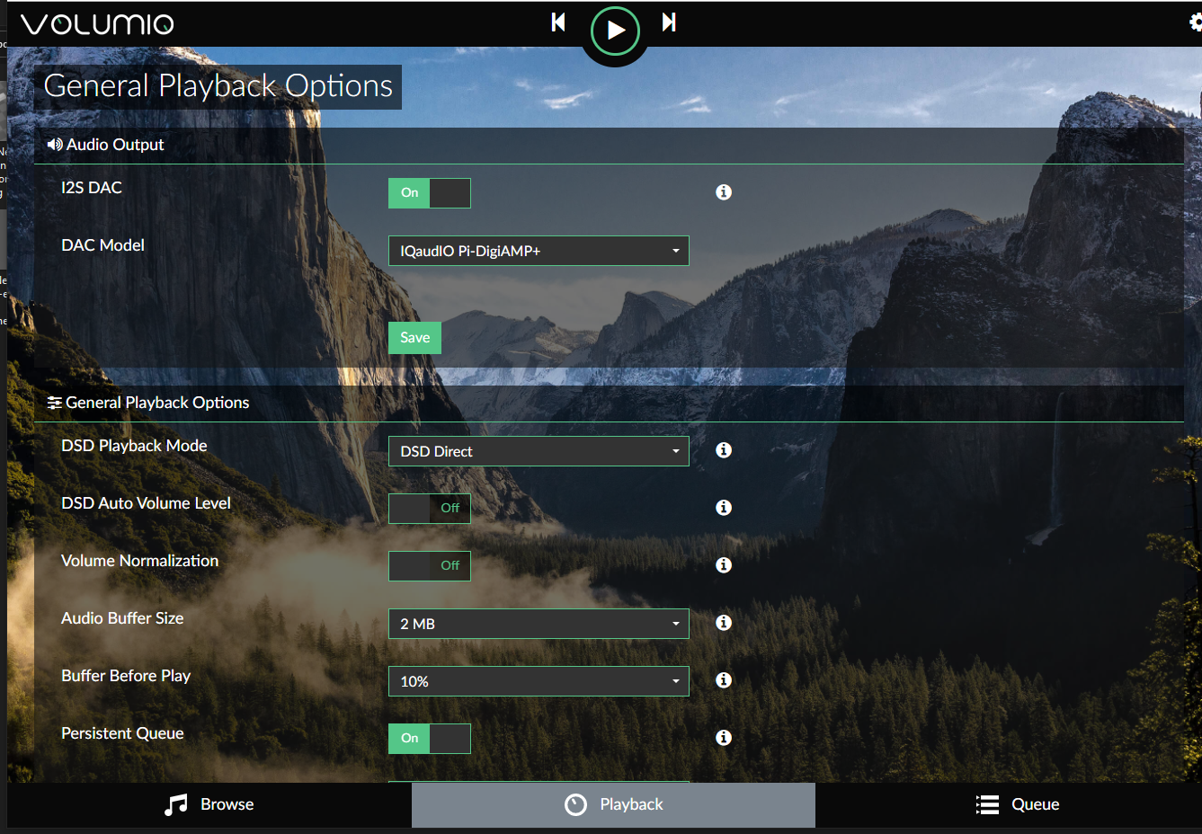
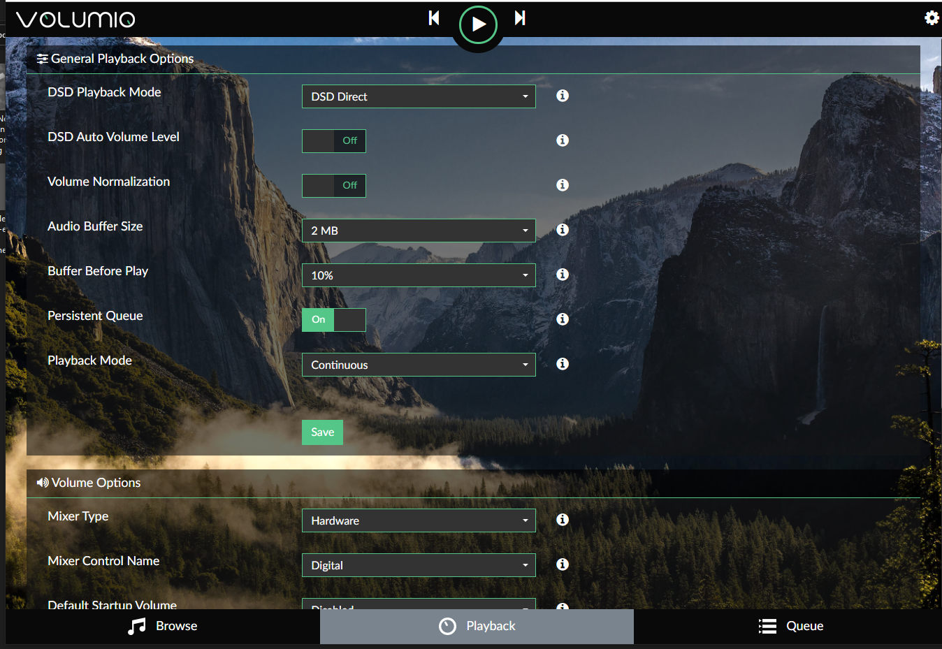
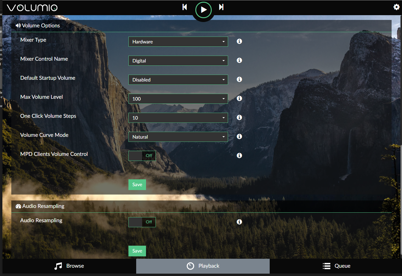
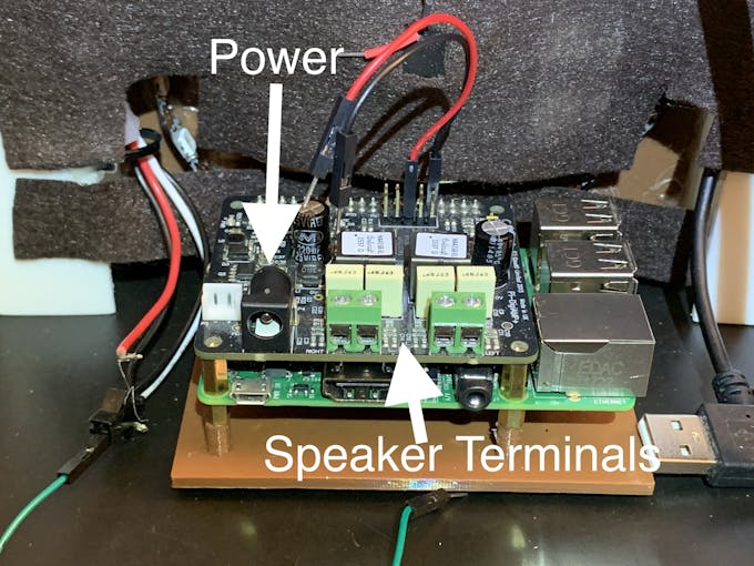
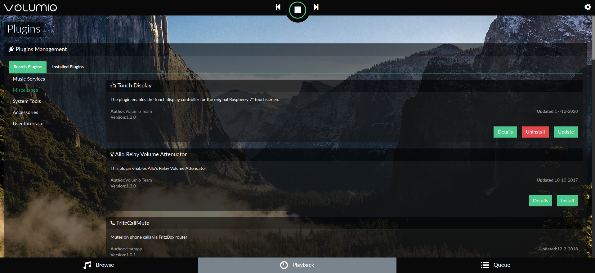
Para comenzar a usar Volumio, consulte la Guía de inicio rápido y Primeros pasos con Volumio.
Prepare la placa de circuito
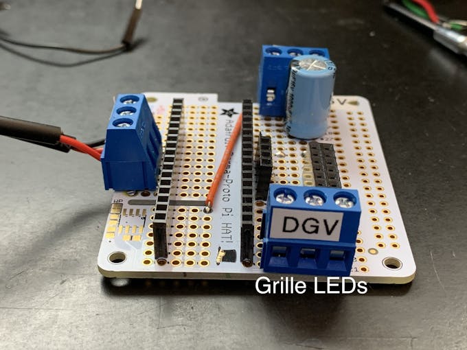
El factor de forma de la placa Adafruit Perma-proto encajaba bien cuando se apilaba sobre el Pi y el amplificador IQAudio, y era una buena placa portadora / secundaria para Arduino.
La placa solo está conectada a IQAudio 5V y GND para alimentación. Por lo tanto, no se usó el encabezado femenino habitual para conectarse a un Pi.
Para aprovechar al máximo el espacio disponible en la placa proto, oriente la placa de modo que el riel marcado "3.3V" esté en la parte superior.
Estoy modificando la placa proto de formas que son un poco menos comunes que solo cablear punto a punto:
- El riel de 3,3 V en realidad se utilizará para entrada de 5 V .
- Huellas de tablas de cortar para colocar varias conexiones de pines en una columna
- Cortar trazos de riel en el riel inferior de 5 V marcado en la placa, para agregar varios pines en una fila
Estas cosas contribuyeron a un tablero bien diseñado, cuando se llenó.
Consulte esta galería de fotos para conocer las conexiones y modificaciones del cableado:
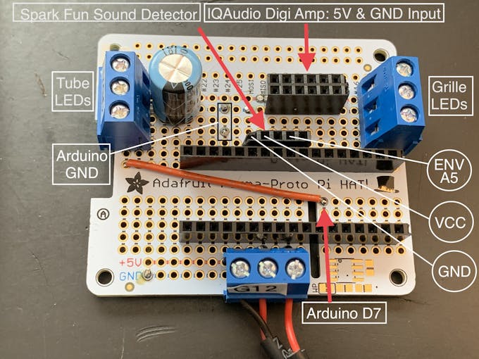
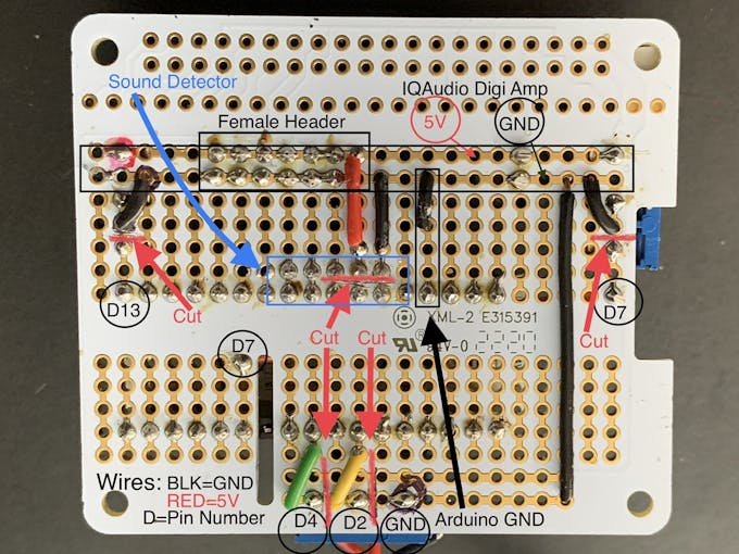
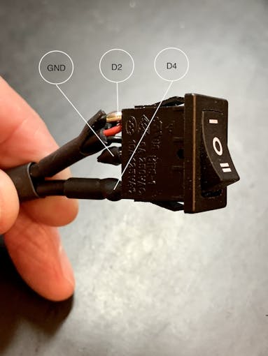
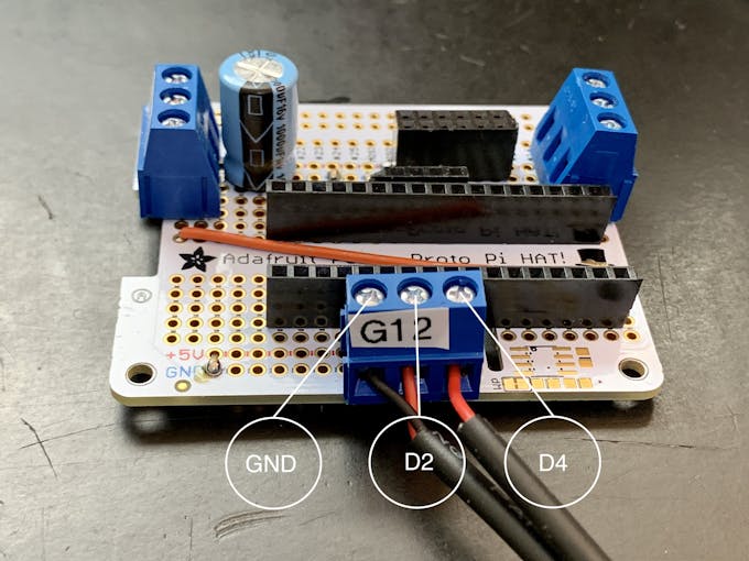
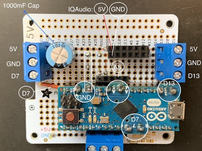 >
> Nota: Los terminales de 3 clavijas tienen un paso de clavija a clavija de 5,08 mm. Eso es exactamente el doble del paso de vías estándar de 2,54 mm en la placa proto. Por lo tanto, los terminales de tornillo / pines están separados por 2 vías de placa. El diseño de la tabla y el corte de la traza dependen de ese espacio. No puede sustituir un terminal de paso de 3 pines / 2,54 mm sin cambiar el diseño de la placa.
Interruptor de selección de animación
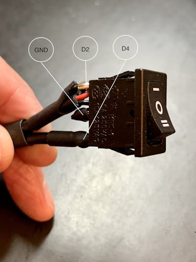
También necesita conectar un interruptor basculante de tres posiciones, que se muestra en las fotos. Corte 3 piezas de cable de conexión de unos 18 cm / 7 pulgadas para este interruptor, preferiblemente dos negros (GND) y uno rojo (+ V).
Más sobre este interruptor a continuación.
Neopixels
Retire la cubierta de silicona de una cuerda de Neopixel de un metro. Corta la tira de Neopixel en dos secciones, una con 36 LED y otra con 22 LED. La franja corta rodeará la rejilla frontal. La tira de 36 LED de longitud estará en los tubos exteriores (tubos de neón). Corta 3 pedazos de alambre de conexión de unos 18 cm / 7 pulgadas por cada hilo (puedes acortarlos más adelante). Conecte cada sección con cables para GND, + V y DIN, asegurándose de que coincida con la dirección DIN en la cadena. Agregue una resistencia en línea con la conexión DIN (330 Ohm funciona).
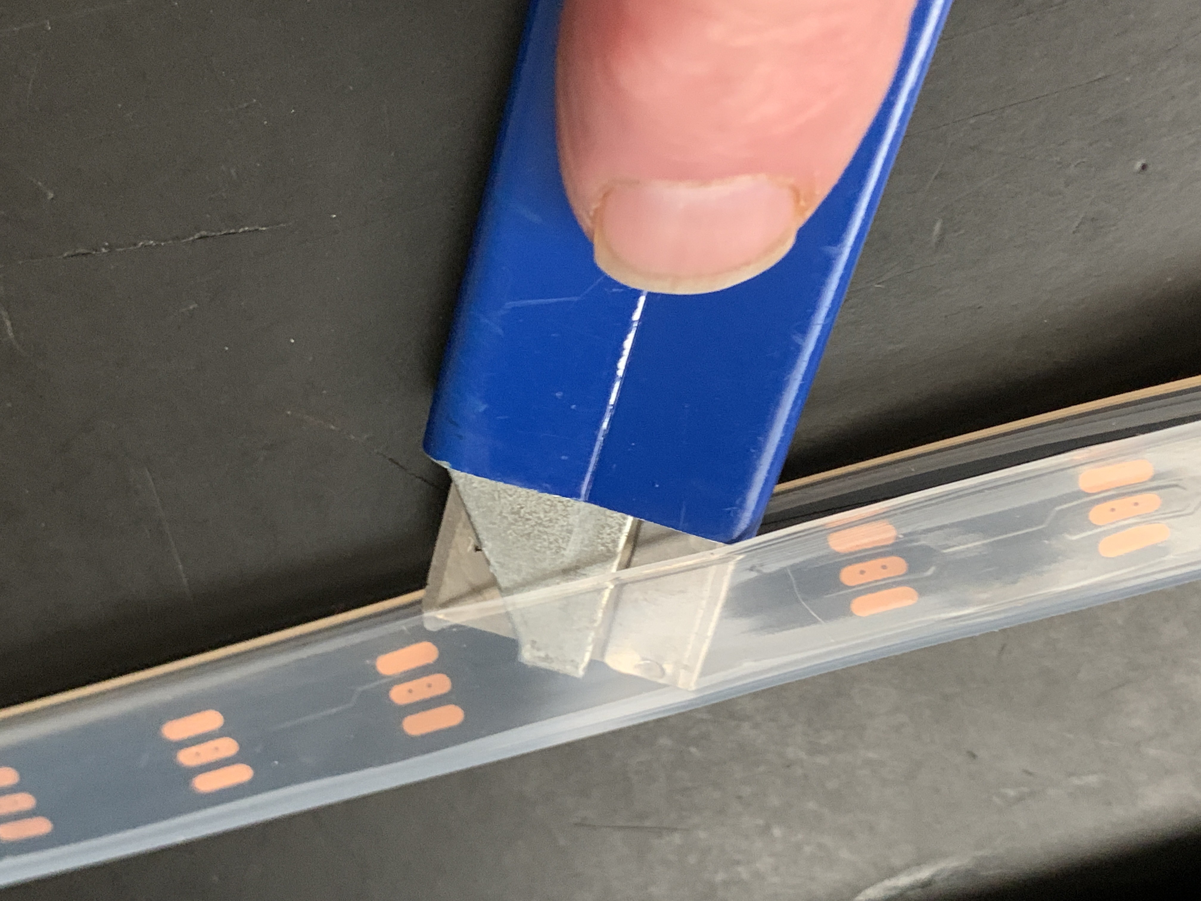
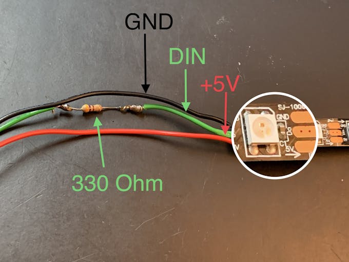
Luz de estrella
En la parrilla frontal, hay un inserto impreso en 3D con forma de estrella de 6 puntas (Star Light). Un LED RGB de atenuación lenta que usa + V y GND se monta detrás de esta Star Light, insertado en un deflector impreso en 3D para evitar el sangrado de la luz. Conecte una resistencia de 120 ohmios en línea en el cable de puente + V. Esto reducirá la corriente de 5 V a aproximadamente 3,4 V en el LED. Esto se utilizará en la sección Ensamblaje / Tela de rejilla, a continuación.
Arduino
Si aún no ha instalado el IDE de Arduino, descárguelo e instálelo siguiendo estas instrucciones.
Necesitará la biblioteca Neopixel para que los LED funcionen.
Los Neopixels reactivos al sonido se basan en el boceto del Visualizador de música LED interactivo de Michael Bartlett en Sparkfun. Usé el "Visualizador completo" sin botones, agregué un interruptor basculante que tiene tres funciones:
- Los LED reaccionan a la música:posición del interruptor 1
- LED en un patrón de "persecución" que cambia de color, NO reactivo al sonido - posición del interruptor 2
- LED apagados:posición del interruptor en el centro
Los LED no funcionarán a menos que el interruptor esté conectado.
Descargue el boceto de los LED de Jukebox de github.
Conexiones
- Monte su Arduino en los encabezados hembra de la placa proto
- Attach the 36-LED strip to the terminal connected to digital pin 7.
- Attach the 22-LED strip to the terminal connected to digital pin 13
- Insert the Sparkfun Sound Detector.
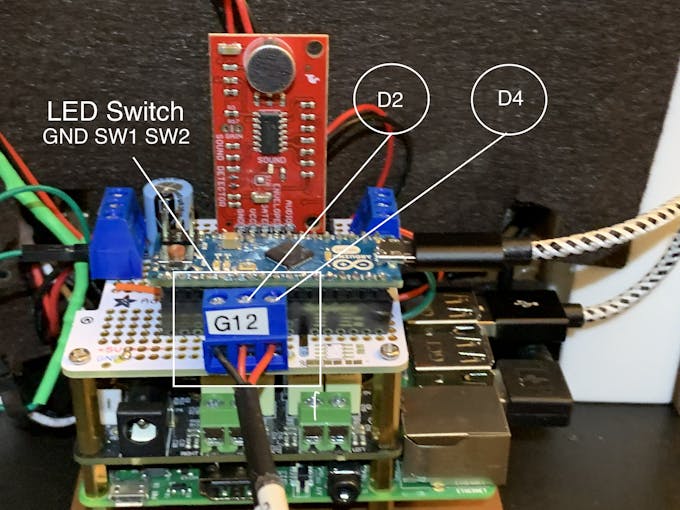
- Attach the Rocker Switch:center pole to GND, position 1 to pin D2, position 2 to pin D4
- Connect the IQAudio Digi Amp Plus +V and GND into the female headers for the 5V rail on the Perma Proto Board (in photos above)
- Connect the slow fade RGB to the +V and GND female headers
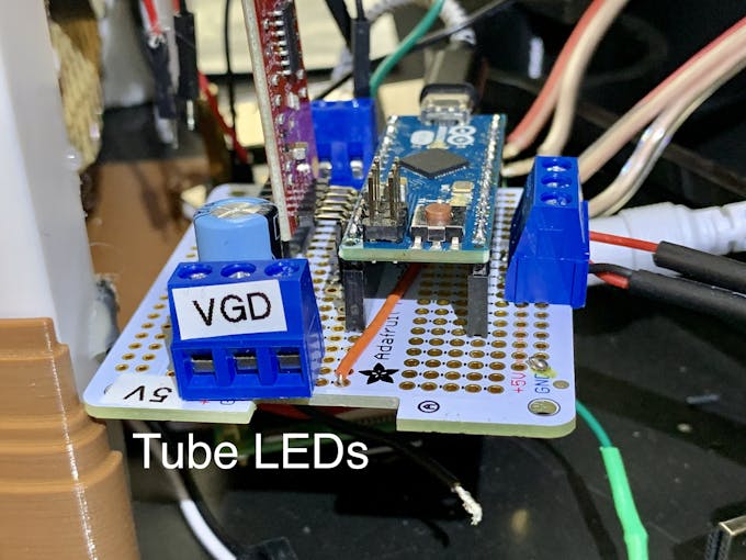
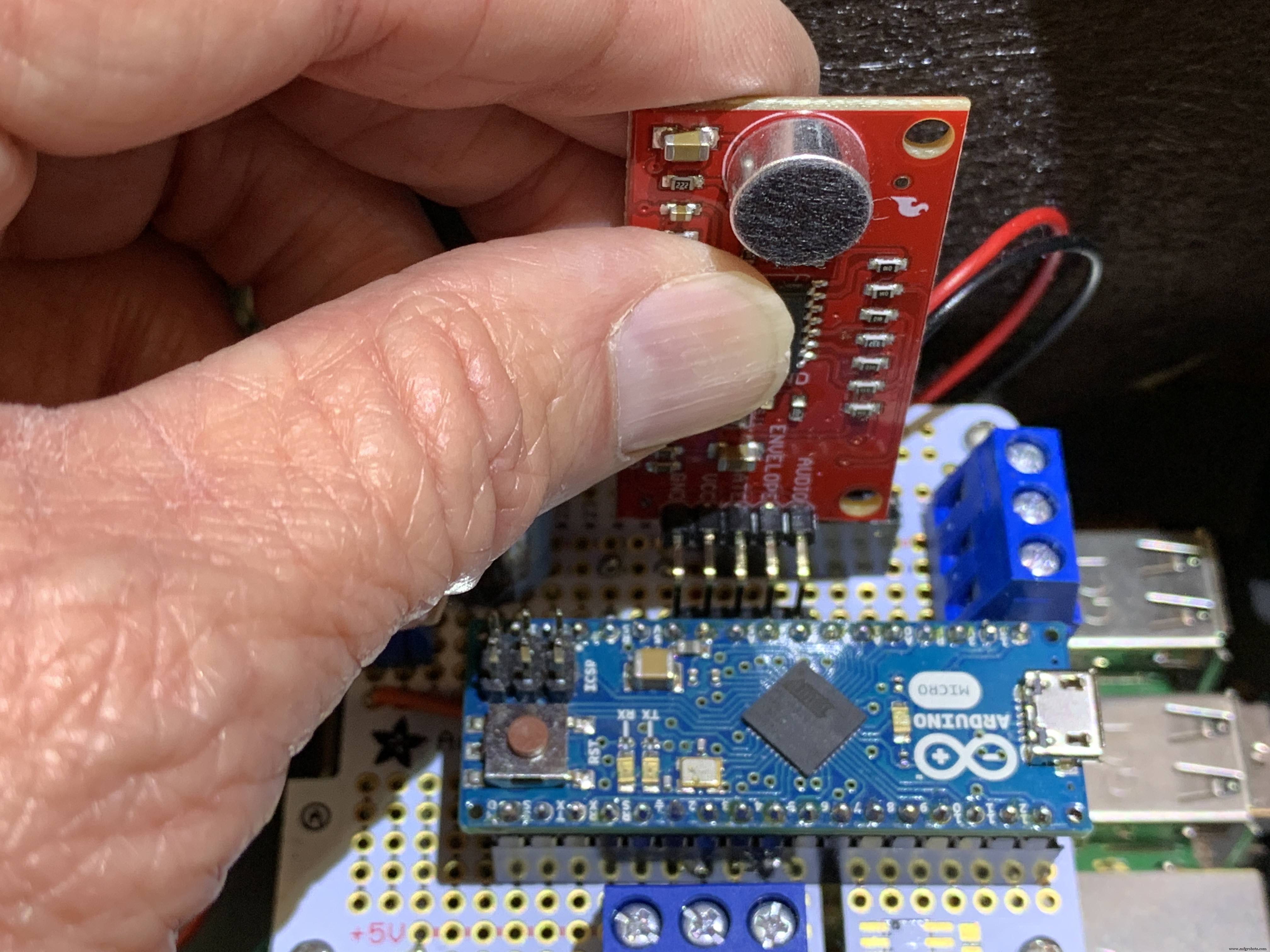
Upload the Jukebox LEDs sketch to your Arduino board. The grille LEDs run through a RainbowCycle routine in the sketch setup function, which takes a little time. So the sound reactive LEDs won't work immediately. After the setup function runs, the grille LEDs will always remain on, unaffected by the position of the rocker switch. With music playing from Volumio, the Neon tubes should react to music with the 3-position rocker switch set to position one. Switch position two passes a color-wheel/chaser pattern through the Neon tubes. Center position on this switch turns the Neon LEDs off.
3D Printing
Check the docs folder of the github download for part identification (Parts List) and Print Times for each part. There are also screenshots of the Prusa Slicer parameters and orientation to guide how to print each part. Find those in the 3D-Prints folder.
NOTE: All images are of the prototype jukebox I built. These will look different from the published Fusion 360 design archive and STL files. The final release STL files include improvements for the following:
- Increase the size of the bezel on the LCD touch screen
- Increase the size of the mounting plate to allow more clearance
- Remove the 3D printed standoffs on the mounting plate and just use holes with screws inserted from the bottom of the mounting plate
- Simplified the back cover
Assembly
Tools
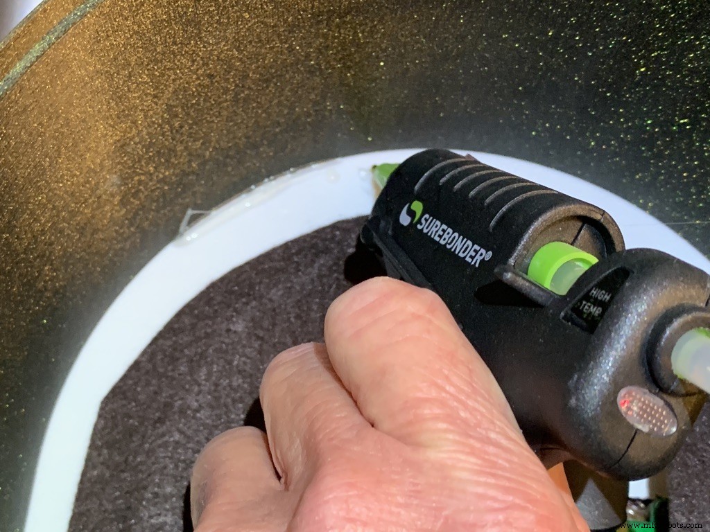
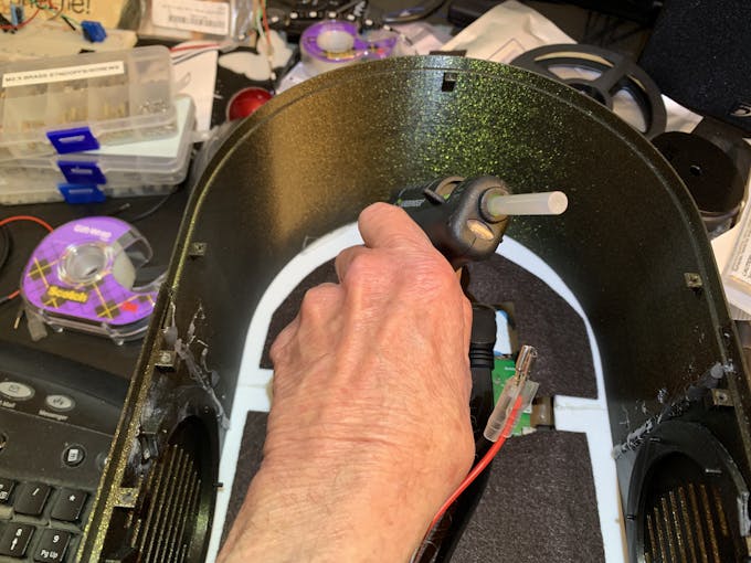
I used a fine-tipped hot glue gun so I could get into smaller spaces. These use smaller diameter glue sticks, and lots of them.
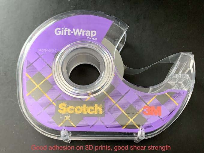
I used some tape I had on hand to temporarily hold the parts together for gluing. I found Scotch Gift-Wrap tape was actually pretty good for this. It has good adhesion and strong shear strength.
Enclosure
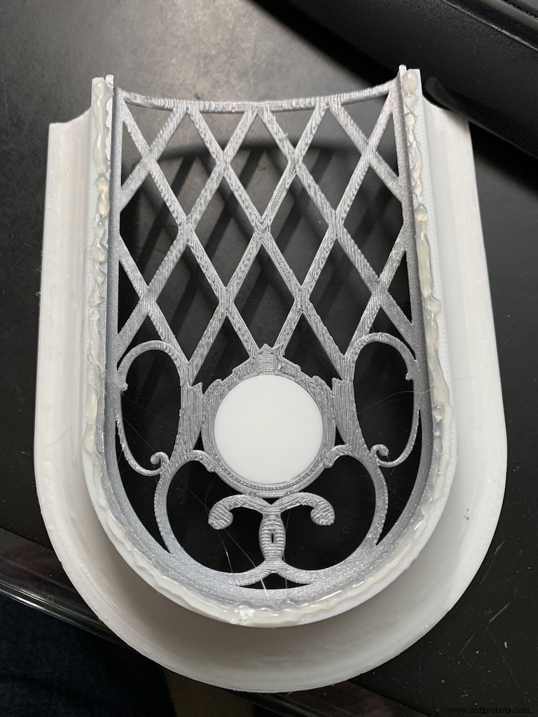
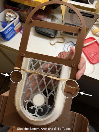
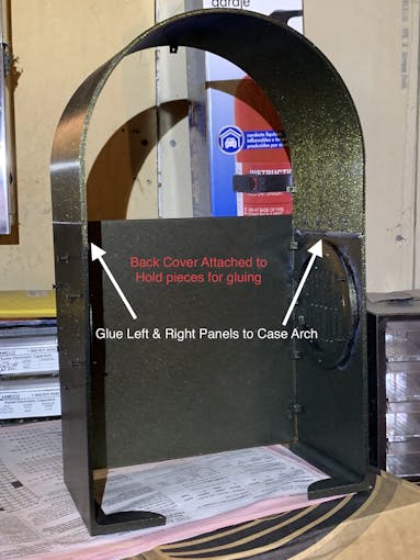
The parts are glued in starting from the inside, the Grille, and moving to the outside, the Neon Tubes, as shown in the video below.
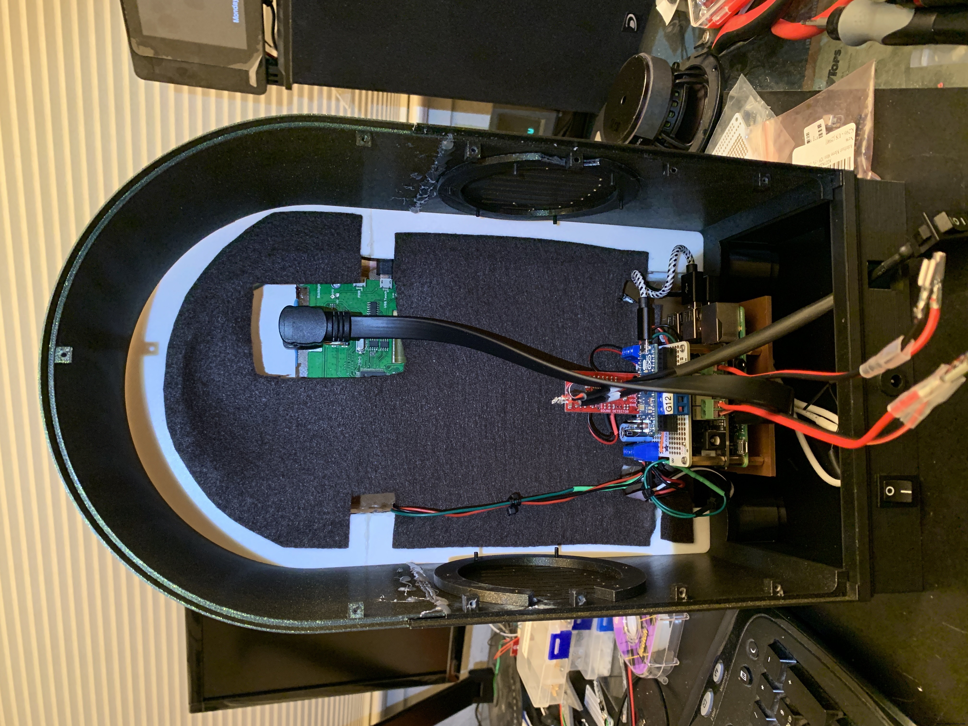
Pause after gluing the Neon Tubes and mount the following hardware. This will give you more space to work in, before you glue in the back case. Refer to the Assembly Gallery photos below for details.
- Acrylic Window with photo
- NeoPixels
- LCD Touch Screen
- Grille Cloth and Star Light Holder
- Raspberry Pi/IQAudio Pi Digi Amp/Arduino
- Adhesive Felt (or paper) backing
- Base with switches
Then continue gluing the Case and Base to the other assembled parts.
After the case is fully assembled and glued together, mount the Speakers and add Decorations.
There is an optional two-piece 3D printed case cover that screws into the back of the case.
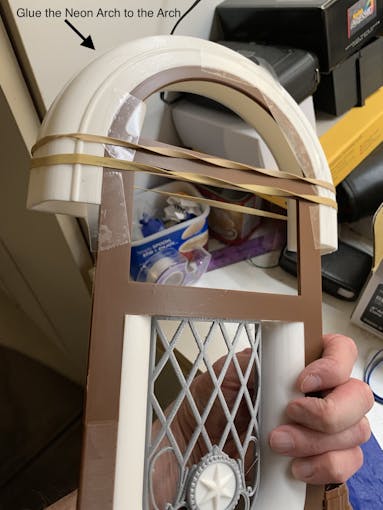
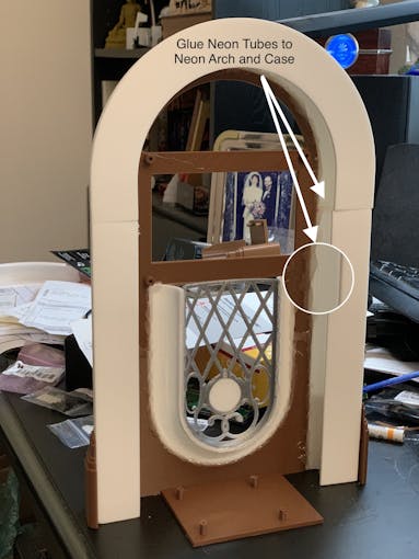
_k2oC39lKQk.jpeg?auto=compress%2Cformat&w=680&h=510&fit=max)
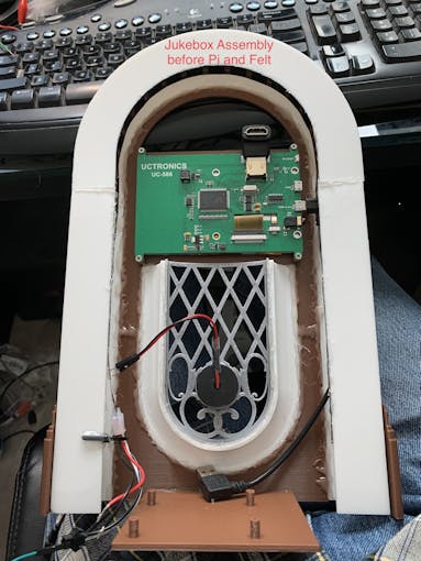
Mounting the Hardware
In the following, all the hardware mentioned is found in the "Things" section.
“Right” and “Left“ are your right and left as you face the front of the jukebox.
Acrylic Window and Photo
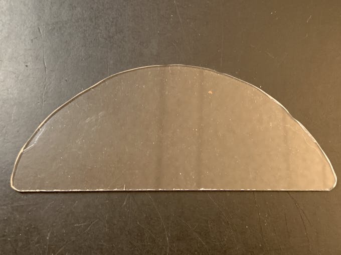
Use a rotary tool (eg., Dremel) at slow speed to cut a piece of clear acrylic. There is a template for this in the github download. Tape the template down on the acrylic and cut around the outside. Sand the edges and use CA to glue into the top of the Arch. Print a photo of your choice that will fill up the visible area and glue that in back of the acrylic.
NeoPixels
Glue the long LED strip edge-on to the Neon Tubes, so that the LEDs are facing inward to the Tubes. There is a small space between the LED and the edge of the strip that can help fit the string against the Neon Tubes. Align that to glue down.
The Grille Tube NeoPixels will be glued onto the Left and Right Bottom, with a "U" shape near the board mounting plate. Hold the strip down with pieces of tape and tack spots with hot glue. When those are solid, remove the tape and fill in the spots where the tape was with more glue.
LCD Touch Screen
Screw the Touch Screen into the mounting posts at the top of the Arch, below the Acrylic window. The HDMI Touch Screen input is on the top of the screen. You need to insert a 90 degree to 270 degree HDMI adapter there, Plug the HDMI 1 ft. Male-to-Male flat cable into the adapter. The other end plugs into a Raspberry Pi 3. (If you're using a Raspberry Pi 4, you need a different cable that has a Micro HDMI in one end). Insert the Left-angle Micro USB to the Touch port on the LCD, and the USB-A end to a Raspberry Pi port. Thread this cable through the left Neon Tube.
Grille Cloth and Star Light Holder
The Grille will be backed with "speaker cloth" to hide the inside of the jukebox. There will be an LED holder behind the Star Light to prevent light bleed, and a hole needs to be cut into the cloth for that.
Cut a piece of speaker cloth large enough to cover the Grille and the edges of the Grille tubes. Use the Star Light LED 3D printed holder as a guide and mark the speaker cloth in a circle for the outside of the holder. Mark a cross in the center of the circle Cut the two lines of the cross to make 4 sections. Cut the rounded part of each section to make a hole for the LED holder.
Mount the color-changing LED mentioned in the section Prepare the Circuit Board/Star Light, above. Insert the LED into the holder and glue it to the Star Light. CA will work well here.
With the LED holder glued in place, fit the speaker cloth over the holder and the Grille. Stretch and glue the edges of the cloth to the Grille Tubes.
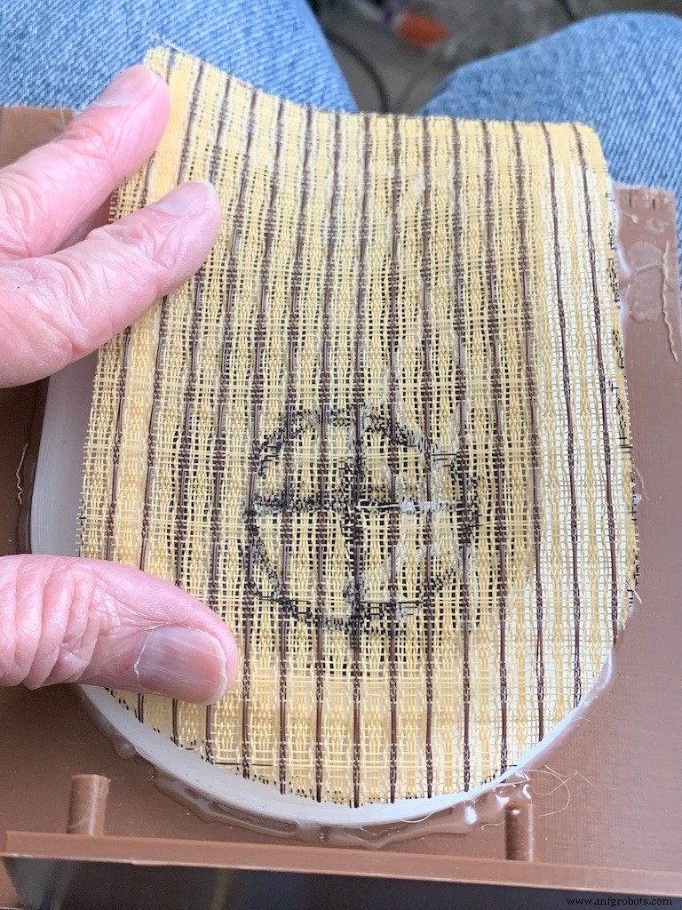
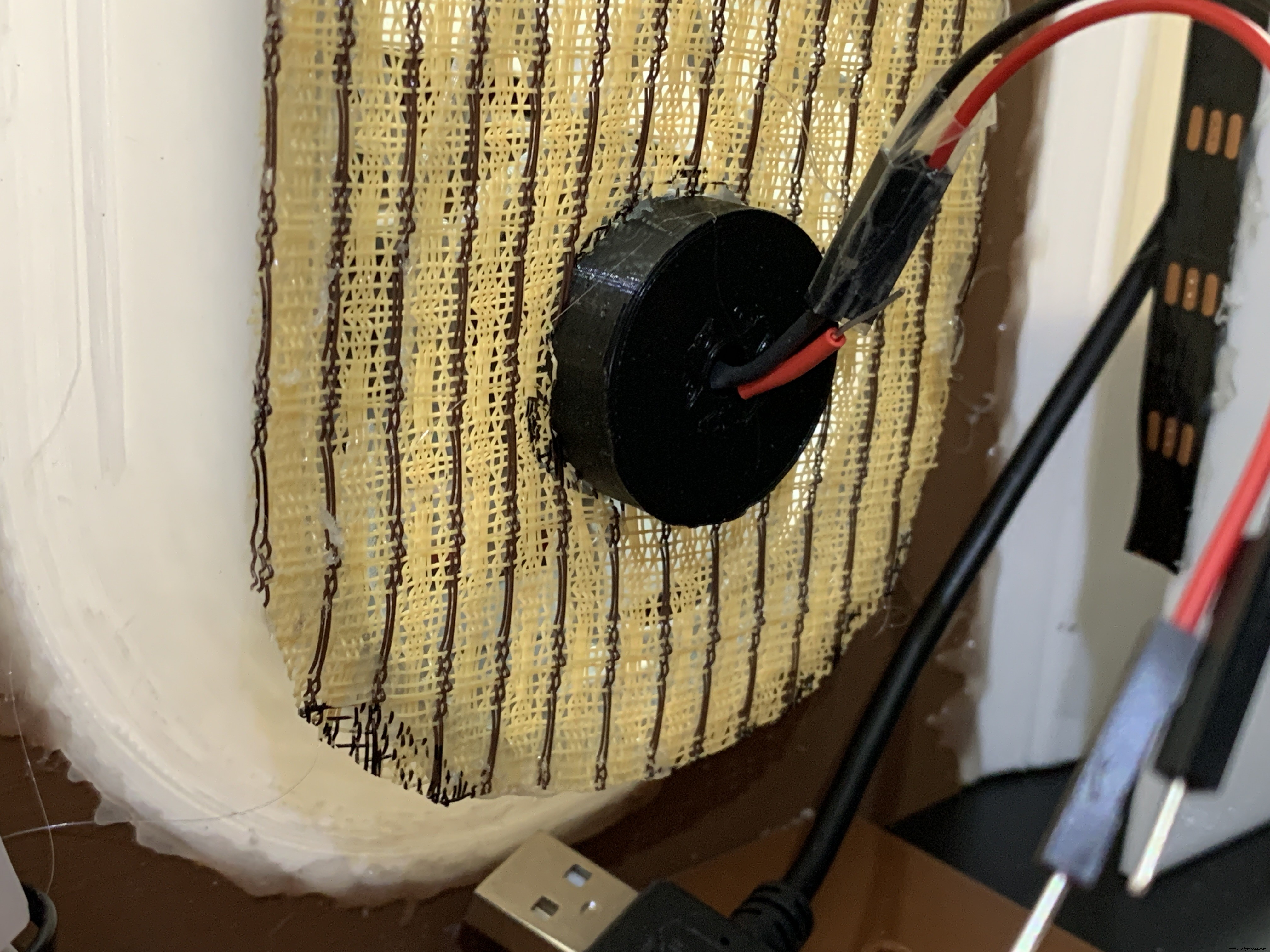
Raspberry Pi/IQAudio Pi Digi Amp/Arduino
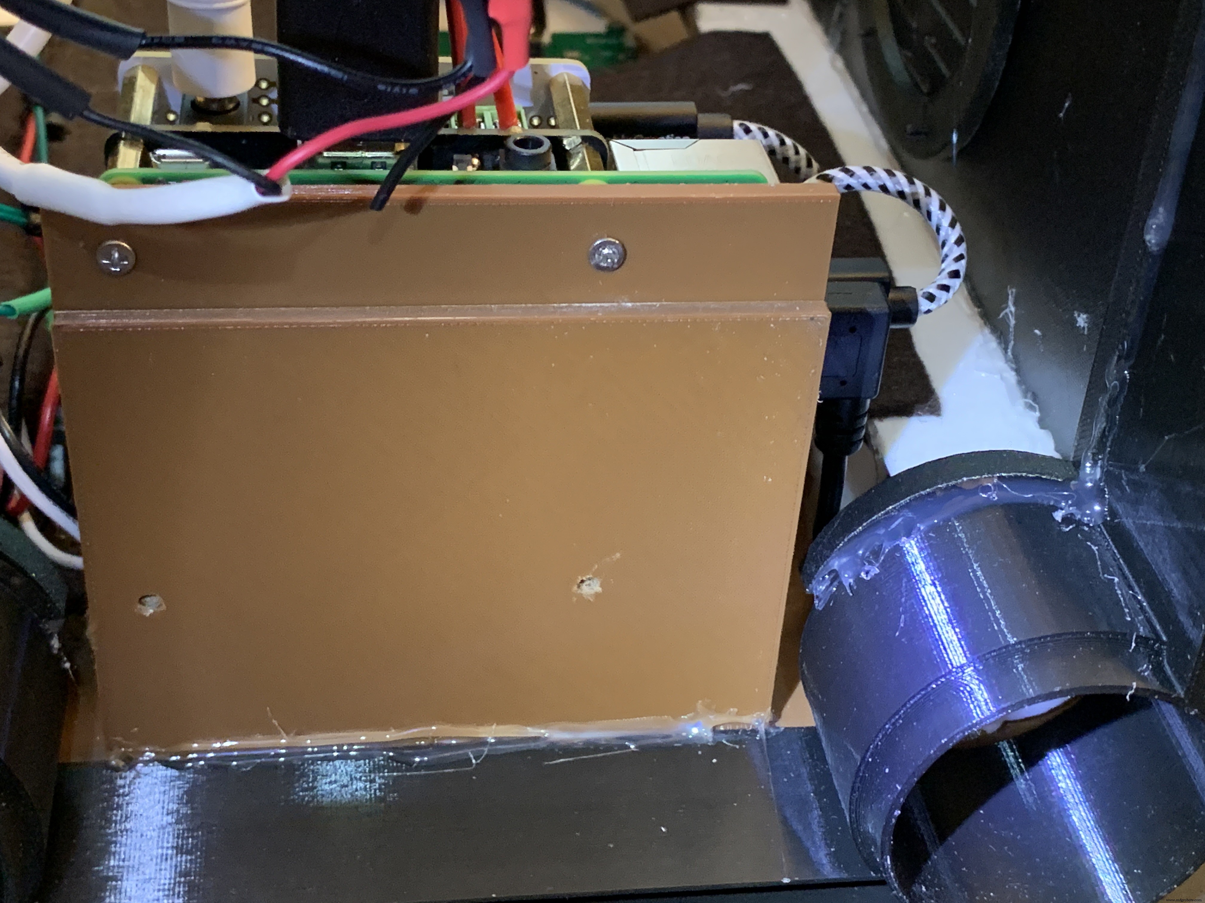
Mount the Pi and other boards (you assembled and tested it in Getting Started, Right ?) onto the mounting plate with screws into the Pi's 5mm bottom standoffs. Plug the LCD HDMI and USB cables into the mounted Pi. There's an additional 6 inch Micro USB to Micro A cable. Plug the Micro end into the Arduino and the other end into the Pi to power the Arduino.
The Star Light +5V and GND plug into the power from the Digi Amp Plus +5V/GND rails.
Adhesive Felt
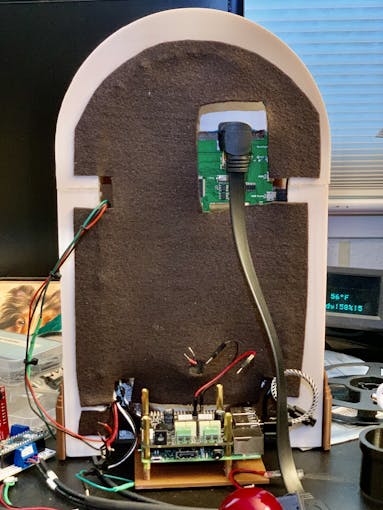
To prevent light bleed, cover the inside with craft felt, which has its own adhesive backing Test fit the felt and cut holes to allow for cables and wires to pass through.
Base with Switches
In addition to the Animation Selector Switch, there is an on-off rocker switch that is connected to a panel-mount jack.
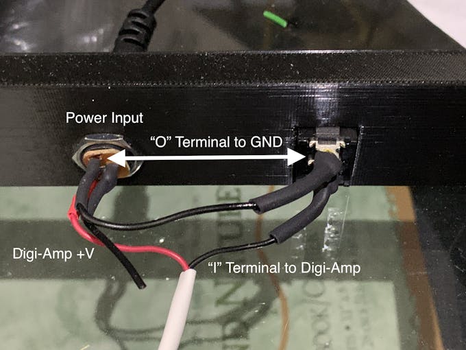
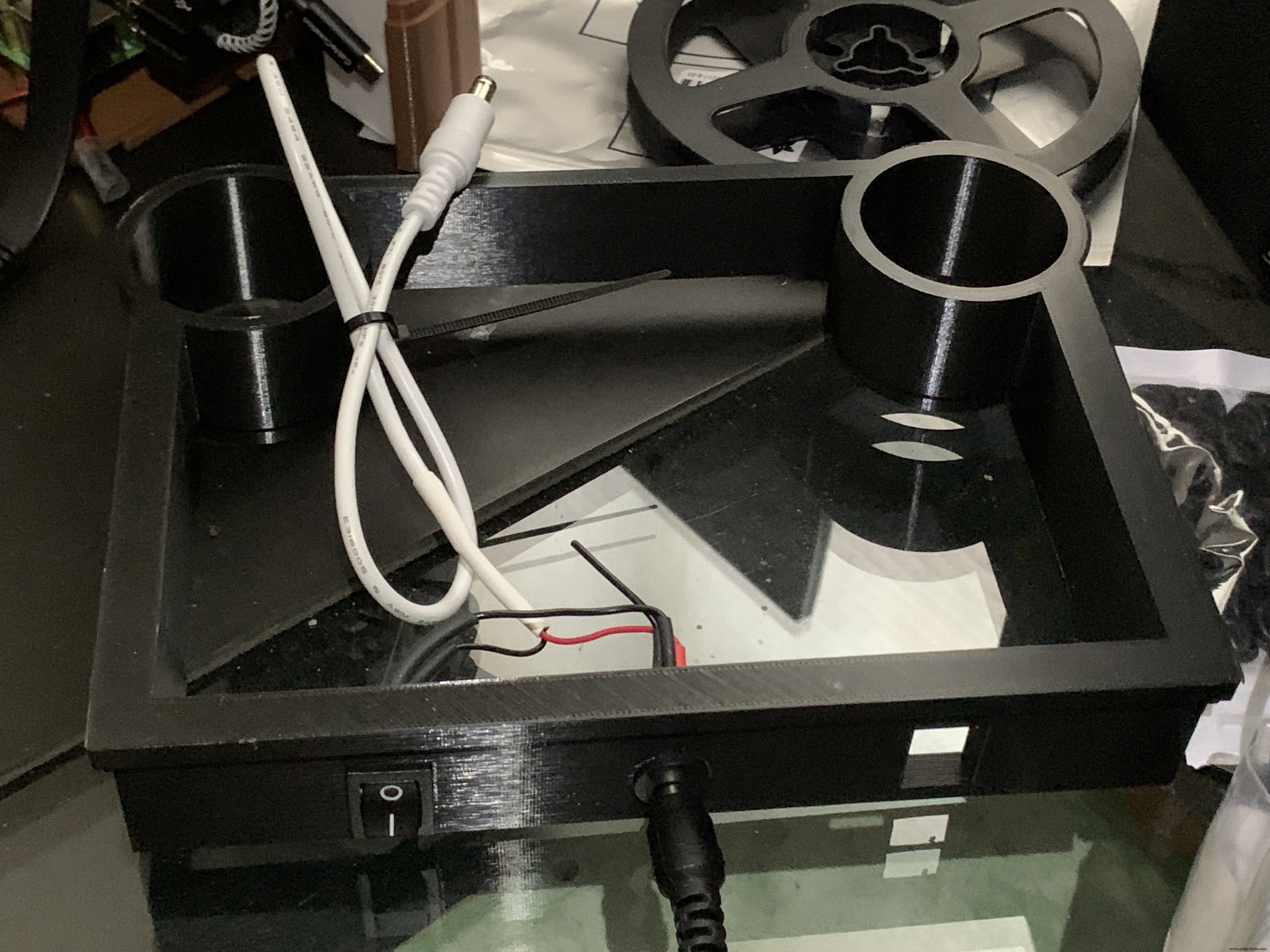
Cut one GND (black) wire at least 80 mm long for this switch. Strip the insulating jacket off the power extension cable (white) in pictures about 80 mm long to expose a red and a black wire. Insert the barrel power connector and the on-off rocker switch into the base.
Solder the cut black wire to the terminal marked "O" on one end, the other end to the active GND pin on the barrel power connector. The other terminal "I" is soldered to the GND (black) of the power extension cable for the Digi Amp Plus Finally, the +V (red) of the power extension cable is soldered to the +V terminal of the barrel connector.
Plug the extension connector into the Pi Digi Amp Plus. Glue the Base onto the Bottom and Case.
Speakers
The Dayton Audio RS100-8 speakers have a cone in the middle that prevents them from being mounted flush to a solid grille, as on this jukebox. If you're using these speakers (or some where the center protrudes), you'll have to use a mounting ring (3D file supplied) so the speakers can mount properly.
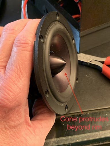
For the last step of assembly, screw the speakers in with 15 mm M2.5 metal screws and nuts.
Tip: To make assembly easier, mount the speaker rings to the case with the screws pushed in for alignment in the holes. Tack down with hot glue or CA glue. When solid, mount the speakers to the rings.
I had pretty good luck holding the tiny nuts down with my index finger and turning the screw to get the nuts started.
However, there is one screw hole straight back on each side that has very little clearance. It is hard to get the nut started on that screw. Putting blu-tack or tape on the nut may help position it to get it started.
Eventually, I did get all the nuts fastened.
Decorations
There are decorations on top and the two sides of the jukebox, with details in the github 3D Parts List document:
- Neon Tube Red Cover
- Neon Tube Fan Decoration
- Neon Tube Ornament
- Case Joint Cover
- Top Red Ornament
- Top Ornament
Repeat for Left &Right:
For the Neon Tubes, use a small ruler to mark the halfway point on the side of the Red Cover with a pencil. Then, match that to the Neon Tube joints and glue with CA.
The long Case Joint Cover aligns to the Neon Tube Red Cover and glues down to the case.
Gllue the Fan Decoration and Ornament at the top and bottom of the Red Cover
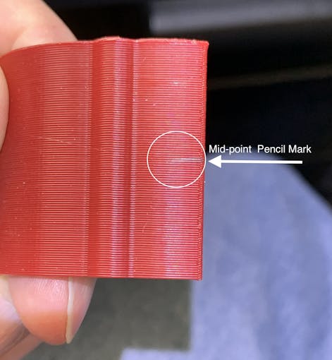
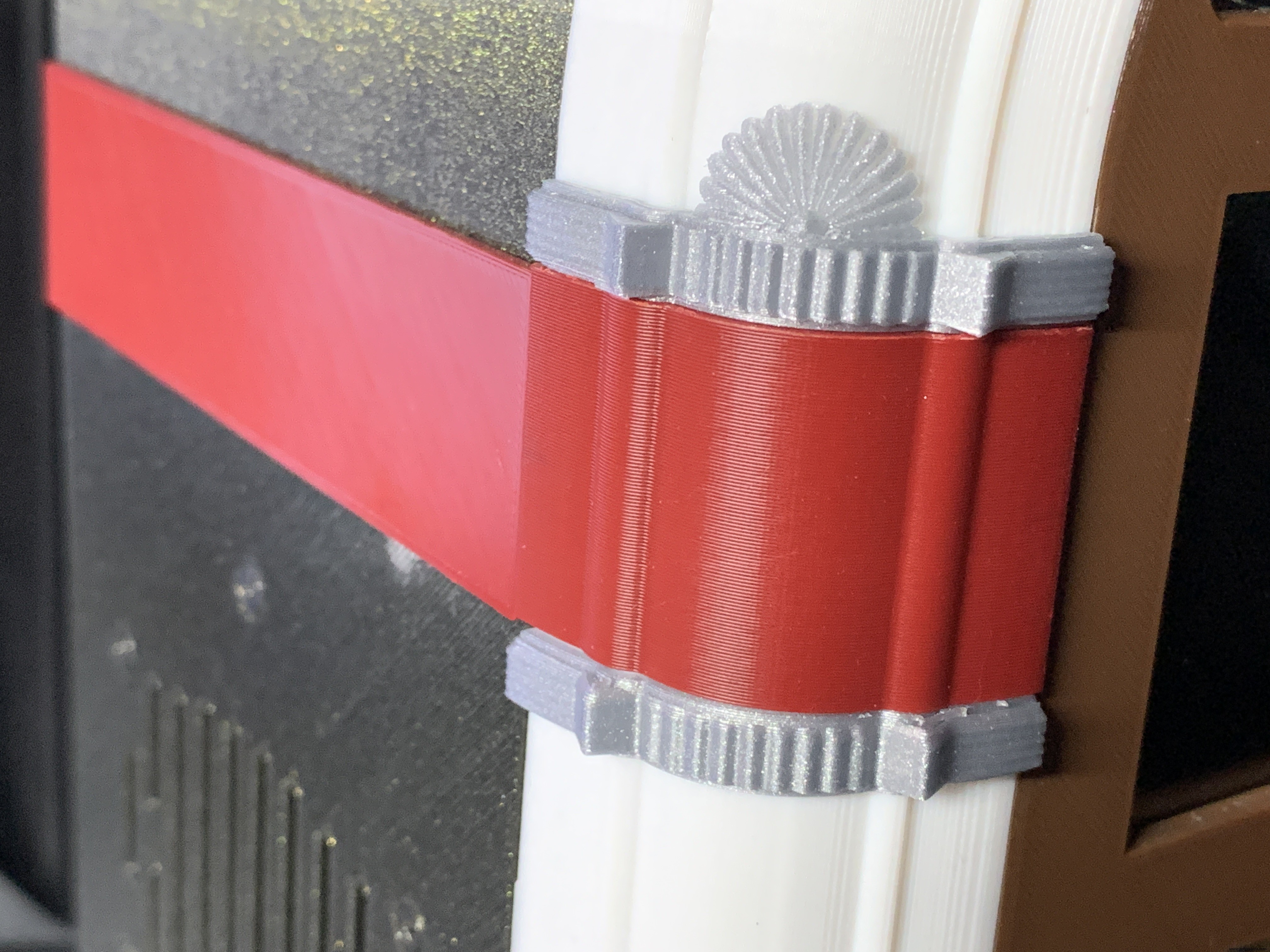
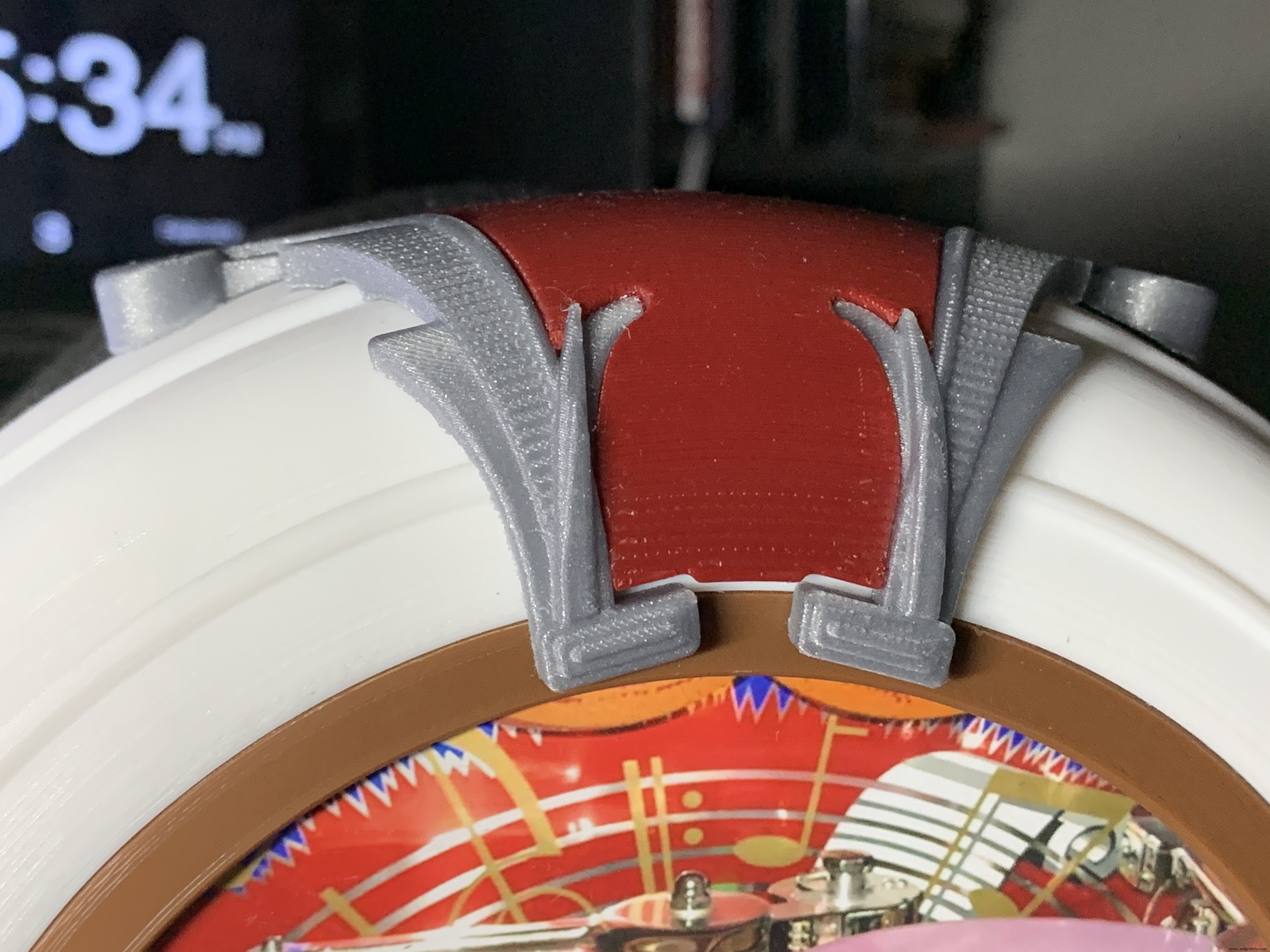
The Top Ornament (2 separate pieces) fits into the Top Red Ornament and is glued together as an assembly.
For alignment, make a pencil mark midway at the top of the Arch and another mark midway on the Top Red Cover. Align these two marks and glue.
Operation
Volumio has a fairly intuitive user interface that's easy to use.
To get started, press/select the 'Home' icon or the 'Browse' button from the 'Playback' window..You'll see something like the image below, depending on what options you have installed.
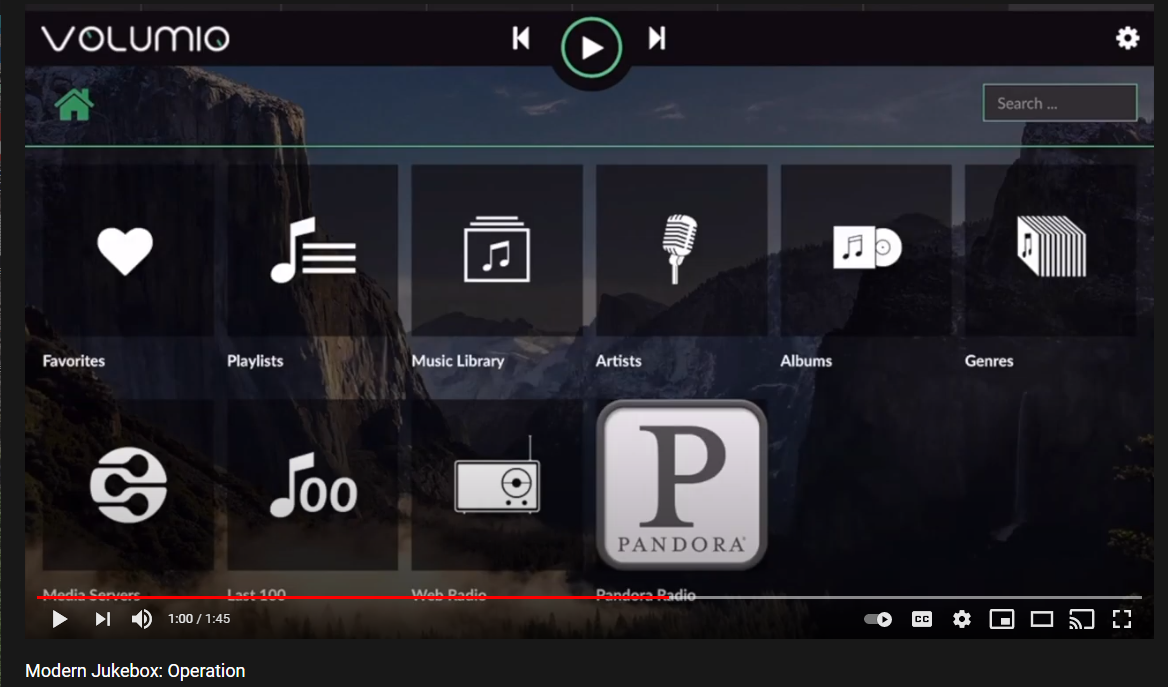
For Pandora and Spotify (paid subscription required), go to Settings/Plugins/Music Services. You can connect to Volumio from AirPlay with the Apple Music player.
Update September 20, 2021:
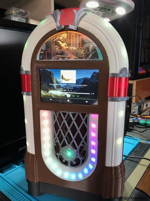
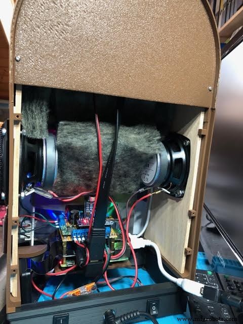
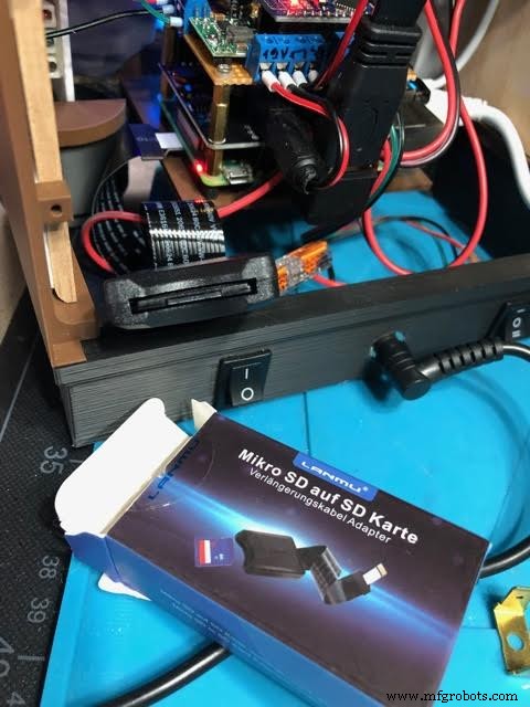
Raimund Trierscheid made a version of the Modern Jukebox, with improvements! Raimund added 5mm wood panels to the sides of the case to hold the heavy speakers and improve the sound.
Here are some photos:
Código
Modern-Jukebox on github
https://github.com/thisoldgeek/Modern-JukeboxPiezas y carcasas personalizadas
Fusion 360 design modern_jukebox_r1_v2_dccOE3MSIQ.f3dProceso de manufactura
- Memoria no mecánica moderna
- Jukebox
- Arco de violín
- Windows 10 IoT Core en Raspberry Pi 2 - Datos del sensor Adafruit
- Un giro moderno en FMEA
- El desarrollo de plásticos modernos
- Sprout:maceta moderna con riego automático para interiores
- UnifiedWater v1
- Cuadro de votación móvil
- Arduino101 / tinyTILE BLE:Gafas de sol para combinar
- Whac-A-Mole (Edición Botón)


