


Cómo construir su primer intermitente LED FPGA:un tutorial paso a paso
Guía paso a paso:construcción de su primer intermitente LED FPGA
Parte 1:Diseño de VHDL o Verilog
En este tutorial aprenderá a crear código VHDL y Verilog que controle un LED a una frecuencia definida por el usuario. Elija el idioma que mejor se adapte a su flujo de trabajo.
Al escribir HDL, debe verificar que el diseño se comporte según lo previsto. Los errores son inevitables, por eso la simulación es indispensable. Este tutorial se divide en dos fases críticas:
- Diseño HDL
- Simulación HDL
Omitir la simulación puede generar una costosa depuración en el hardware. Trate la simulación como un punto de control obligatorio.
Requisitos del proyecto
Escriba HDL que haga parpadear un LED a 100 Hz, 50 Hz, 10 Hz o 1 Hz con un ciclo de trabajo del 50 %. Dos interruptores seleccionan la frecuencia deseada y un LED_EN adicional El interruptor debe estar alto para habilitar el LED. La FPGA funciona con un oscilador de 25 MHz.
Tabla de verdad para el selector de frecuencia:
| Habilitar | Interruptor1 | Interruptor2 | Frecuencia de accionamiento LED |
|---|---|---|---|
| 0 | – | – | deshabilitado |
| 1 | 0 | 0 | 100Hz |
| 1 | 0 | 1 | 50Hz |
| 1 | 1 | 0 | 10 Hz |
| 1 | 1 | 1 | 1 Hz |
Resumen de señal:
| Nombre de la señal | Dirección | Descripción |
|---|---|---|
| i_clock | Entrada | Reloj de 25MHz |
| i_enable | Entrada | Habilitar interruptor (logic0 =LED apagado) |
| i_switch_1 | Entrada | Interruptor selector de frecuencia1 |
| i_switch_2 | Entrada | Interruptor selector de frecuencia2 |
| o_led_drive | Salida | Señal de accionamiento LED |
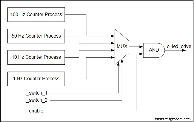
Cuatro procesos de contador simultáneos monitorean el reloj de 25MHz y generan alternancias para cada frecuencia objetivo. Incluso cuando no se selecciona una frecuencia particular, su contador continúa ejecutándose, un principio básico de la concurrencia de hardware.
Los interruptores forman un multiplexor que dirige el interruptor elegido a la salida del LED. Los multiplexores son puramente lógicos combinacionales, por lo que funcionan sin reloj.
A continuación se muestra un diagrama de bloques que ilustra la arquitectura:
Implementación de VHDL
library ieee;
use ieee.std_logic_1164.all;
use ieee.numeric_std.all;
entity tutorial_led_blink is
 port (
 i_clock : in std_logic;
 i_enable : in std_logic;
 i_switch_1 : in std_logic;
 i_switch_2 : in std_logic;
 o_led_drive : out std_logic
 );
end tutorial_led_blink;
architecture rtl of tutorial_led_blink is
 -- Constants to create the frequencies needed:
 -- Formula is: (25 MHz / 100 Hz * 50% duty cycle)
 -- So for 100 Hz: 25,000,000 / 100 * 0.5 = 125,000
 constant c_CNT_100HZ : natural := 125000;
 constant c_CNT_50HZ : natural := 250000;
 constant c_CNT_10HZ : natural := 1250000;
 constant c_CNT_1HZ : natural := 12500000;
 -- These signals will be the counters:
 signal r_CNT_100HZ : natural range 0 to c_CNT_100HZ;
 signal r_CNT_50HZ : natural range 0 to c_CNT_50HZ;
 signal r_CNT_10HZ : natural range 0 to c_CNT_10HZ;
 signal r_CNT_1HZ : natural range 0 to c_CNT_1HZ;

 -- These signals will toggle at the frequencies needed:
 signal r_TOGGLE_100HZ : std_logic := '0';
 signal r_TOGGLE_50HZ : std_logic := '0';
 signal r_TOGGLE_10HZ : std_logic := '0';
 signal r_TOGGLE_1HZ : std_logic := '0';
 -- One bit select wire.
 signal w_LED_SELECT : std_logic;

begin
 -- All processes toggle a specific signal at a different frequency.
 -- They all run continuously even if the switches are
 -- not selecting their particular output.

 p_100_HZ : process (i_clock) is
 begin
 if rising_edge(i_clock) then
 if r_CNT_100HZ = c_CNT_100HZ-1 then -- -1, since counter starts at 0
 r_TOGGLE_100HZ <= not r_TOGGLE_100HZ;
 r_CNT_100HZ <= 0;
 else
 r_CNT_100HZ <= r_CNT_100HZ + 1;
 end if;
 end if;
 end process p_100_HZ;
 p_50_HZ : process (i_clock) is
 begin
 if rising_edge(i_clock) then
 if r_CNT_50HZ = c_CNT_50HZ-1 then -- -1, since counter starts at 0
 r_TOGGLE_50HZ <= not r_TOGGLE_50HZ;
 r_CNT_50HZ <= 0;
 else
 r_CNT_50HZ <= r_CNT_50HZ + 1;
 end if;
 end if;
 end process p_50_HZ;

 p_10_HZ : process (i_clock) is
 begin
 if rising_edge(i_clock) then
 if r_CNT_10HZ = c_CNT_10HZ-1 then -- -1, since counter starts at 0
 r_TOGGLE_10HZ <= not r_TOGGLE_10HZ;
 r_CNT_10HZ <= 0;
 else
 r_CNT_10HZ <= r_CNT_10HZ + 1;
 end if;
 end if;
 end process p_10_HZ;

 p_1_HZ : process (i_clock) is
 begin
 if rising_edge(i_clock) then
 if r_CNT_1HZ = c_CNT_1HZ-1 then -- -1, since counter starts at 0
 r_TOGGLE_1HZ <= not r_TOGGLE_1HZ;
 r_CNT_1HZ <= 0;
 else
 r_CNT_1HZ <= r_CNT_1HZ + 1;
 end if;
 end if;
 end process p_1_HZ;

 -- Create a multiplexor based on switch inputs
 w_LED_SELECT <= r_TOGGLE_100HZ when (i_switch_1 = '0' and i_switch_2 = '0') else
 r_TOGGLE_50HZ when (i_switch_1 = '0' and i_switch_2 = '1') else
 r_TOGGLE_10HZ when (i_switch_1 = '1' and i_switch_2 = '0') else
 r_TOGGLE_1HZ;

 -- Only allow o_led_drive to drive when i_enable is high (and gate).
 o_led_drive <= w_LED_SELECT and i_enable;
end rtl;
Implementación de Verilog
module tutorial_led_blink
(
 i_clock,
 i_enable,
 i_switch_1,
 i_switch_2,
 o_led_drive
 );
 input i_clock;
 input i_enable;
 input i_switch_1;
 input i_switch_2;
 output o_led_drive;

 // Constants (parameters) to create the frequencies needed:
 // Input clock is 25 kHz, chosen arbitrarily.
 // Formula is: (25 kHz / 100 Hz * 50% duty cycle)
 // So for 100 Hz: 25,000 / 100 * 0.5 = 125
 parameter c_CNT_100HZ = 125;
 parameter c_CNT_50HZ = 250;
 parameter c_CNT_10HZ = 1250;
 parameter c_CNT_1HZ = 12500;
 // These signals will be the counters:
 reg [31:0] r_CNT_100HZ = 0;
 reg [31:0] r_CNT_50HZ = 0;
 reg [31:0] r_CNT_10HZ = 0;
 reg [31:0] r_CNT_1HZ = 0;

 // These signals will toggle at the frequencies needed:
 reg r_TOGGLE_100HZ = 1'b0;
 reg r_TOGGLE_50HZ = 1'b0;
 reg r_TOGGLE_10HZ = 1'b0;
 reg r_TOGGLE_1HZ = 1'b0;

 // One bit select
 reg r_LED_SELECT;
 wire w_LED_SELECT;


begin
 // All always blocks toggle a specific signal at a different frequency.
 // They all run continuously even if the switches are
 // not selecting their particular output.
 always @ (posedge i_clock)
 begin
 if (r_CNT_100HZ == c_CNT_100HZ-1) // -1, since counter starts at 0
 begin
 r_TOGGLE_100HZ <= !r_TOGGLE_100HZ;
 r_CNT_100HZ <= 0;
 end
 else
 r_CNT_100HZ <= r_CNT_100HZ + 1;
 end

 always @ (posedge i_clock)
 begin
 if (r_CNT_50HZ == c_CNT_50HZ-1) // -1, since counter starts at 0
 begin
 r_TOGGLE_50HZ <= !r_TOGGLE_50HZ;
 r_CNT_50HZ <= 0;
 end
 else
 r_CNT_50HZ <= r_CNT_50HZ + 1;
 end
 always @ (posedge i_clock)
 begin
 if (r_CNT_10HZ == c_CNT_10HZ-1) // -1, since counter starts at 0
 begin
 r_TOGGLE_10HZ <= !r_TOGGLE_10HZ;
 r_CNT_10HZ <= 0;
 end
 else
 r_CNT_10HZ <= r_CNT_10HZ + 1;
 end

 always @ (posedge i_clock)
 begin
 if (r_CNT_1HZ == c_CNT_1HZ-1) // -1, since counter starts at 0
 begin
 r_TOGGLE_1HZ <= !r_TOGGLE_1HZ;
 r_CNT_1HZ <= 0;
 end
 else
 r_CNT_1HZ <= r_CNT_1HZ + 1;
 end
 // Create a multiplexer based on switch inputs
 always @ (*)
 begin
 case () // Concatenation Operator
 2'b11 : r_LED_SELECT <= r_TOGGLE_1HZ;
 2'b10 : r_LED_SELECT <= r_TOGGLE_10HZ;
 2'b01 : r_LED_SELECT <= r_TOGGLE_50HZ;
 2'b00 : r_LED_SELECT <= r_TOGGLE_100HZ;
 endcase
 end
 assign o_led_drive = r_LED_SELECT & i_enable;
 // Alternative way to design multiplexer (same as above):
 // More compact, but harder to read, especially to those new to Verilog
 // assign w_LED_SELECT = i_switch_1 ? (i_switch_2 ? r_TOGGLE_1HZ : r_TOGGLE_10HZ) :
 //(i_switch_2 ? r_TOGGLE_50HZ : r_TOGGLE_100HZ);
 // assign o_led_drive = w_LED_SELECT & i_enable;


end

endmodule
Siguiente paso:simule este diseño en VHDL o Verilog para confirmar el comportamiento correcto antes de la implementación.
VHDL
- Cómo usar Loop y Exit en VHDL
- Cómo usar un procedimiento en un proceso en VHDL
- Cómo usar una instrucción Case-When en VHDL
- Cuestionario básico de VHDL - parte 2
- Curso FPGA – Todo lo que necesitas saber sobre el Curso Dot Matrix VHDL
- En qué se diferencia una señal de una variable en VHDL
- Cómo usar la creación de instancias de mapas de puertos en VHDL
- Cómo crear una declaración concurrente en VHDL
- Cómo crear un FIFO de búfer de anillo en VHDL
- Cuestionario básico de VHDL - parte 4
- Cómo crear un proceso con una Lista de Sensibilidad en VHDL