



Construye tu Propio Comedero Inteligente para Mascotas con Arduino Nano
Componentes y materiales
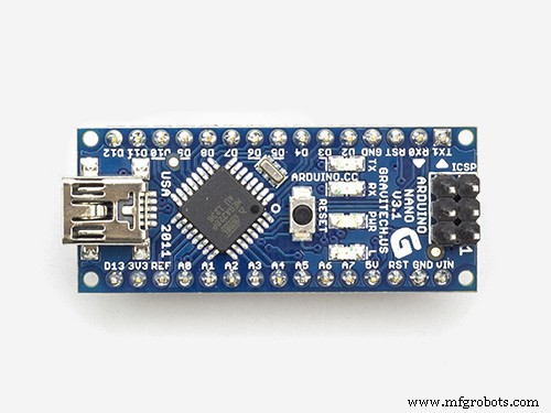 |
Arduino Nano R3
Mejor usar un Arduino Nano si quieres una carcasa compacta
|
× | 1 | |
|
Adafruit Reloj en Tiempo Real
|
× | 1 | ||
|
Servo de Rotación Continua
|
× | 1 | ||
|
Dispensador de cereales
|
× | 1 | ||
|
Sensor Hall UNIPOLAR
|
× | 1 | ||
|
Imanes de varilla 3mm diámetro, 5mm longitud
|
× | 6 | ||
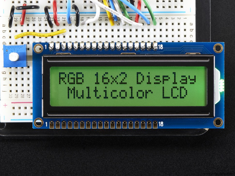 |
Adafruit LCD Retroiluminado RGB - 16x2
|
× | 1 | |
|
Mochila i2c para LCD
|
× | 1 | ||
|
Pulsador Apem momentáneo IP67
|
× | 1 | ||
|
Pequeños pulsadores momentáneos
|
× | 1 | ||
 |
LED (genérico)
|
× | 6 | |
|
Carcasa ABS Hammond con brida
|
× | 1 |
Aplicaciones y servicios en línea
|
Generador de caracteres LCD
|
Acerca de este proyecto
Actualización 2018-09-06
Mis dos comederos para mascotas funcionan perfectamente desde hace 7 meses. Cuidamos a nuestras mascotas durante el día, por supuesto, pero ahora reciben su comida a horas regulares. ¡Muy contento con el sistema!
¿Por qué otro comedero para mascotas?
Mi versión de un comedero para mascotas se basa en un microcontrolador Arduino. Los materiales utilizados son relativamente baratos y creo que es fácil de construir.
Por supuesto, hay muchas versiones por ahí, pero no pude encontrar un proyecto completo, listo para construir con las características que necesitaba, así que empecé desde cero.
Estas son las características:
- Porciones precisas entregadas cada vez (mediante un sensor Hall)
- Dos horarios de alimentación al día
- Extremadamente preciso Reloj en Tiempo Real (Solo con chip DS3231 genuino)
- Puedes cancelar una alimentación próxima individualmente para ambos temporizadores con indicador en pantalla y LED. La cancelación se restablece automáticamente después de que ha pasado la hora programada.
- Función de alimentación manual (una porción por pulsación de botón)
- Porciones ajustables para cada uno de los dos horarios de alimentación (1-9 porciones)
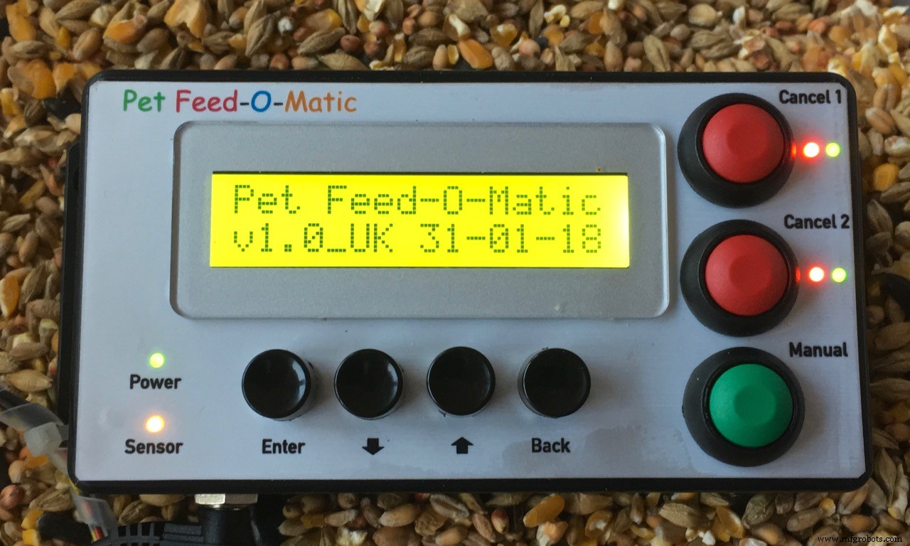
- Resumen de todos los parámetros establecidos en la pantalla principal
- Sistema de menú fácil de navegar
- Indicación LED si la alimentación fue exitosa
- Temporizador de retroiluminación LCD (apagado después de 30 seg, encendido con cualquier pulsación de botón)
- La hora y otros ajustes se guardan de forma segura en memoria (EEPROM)
Videos de demostración:
Para video haz clic AQUÍ
Explicación más detallada en video: haz clic AQUÍ
¡El comedero para mascotas en cámara lenta! haz clic AQUÍ
Fotos:
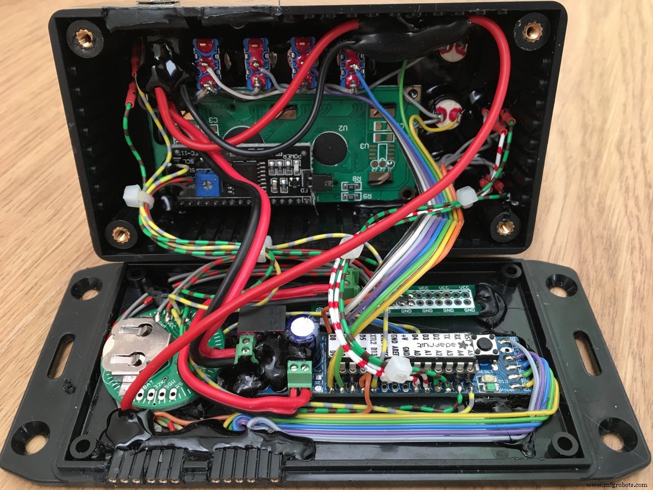
Piezas necesarias:
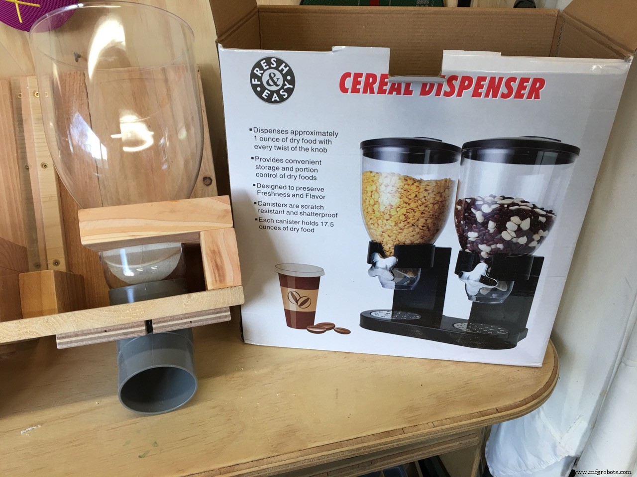
- 1x Dispensador de cereales (barato en Ebay)
- Algo de madera (deshecho) para construir el soporte del dispensador
- 1x Arduino Uno
- 1x I2C DS3231 (extremadamente preciso) o DS1307 Reloj en Tiempo Real
- 1x Pantalla LCD 16 caracteres / 2 líneas
- 1x Mochila I2C para la pantalla LCD
- 1x Servo de Rotación Continua (¡compra uno bueno!)
- 1x Sensor Hall Unipolar Honeywell SS443R
- 1x Fuente de alimentación externa 12Voltios/1 Amperio (transformador de pared)
- 7x Pulsadores - Momentáneos
- 6x LED (2x ROJO, 3x VERDE, 1 AMARILLO)
- 2x resistencia 1KΩ (para los leds rojos)
- 4x resistencia 560Ω (para los leds verde y amarillo)
- 1x carcasa para la electrónica
- enchufe de alimentación hembra y conectores para conectar el servo externo y sensor hall
- mucho y mucho PEGAMENTO CALIENTE.
Es mejor usar un voltaje más alto para el servo si es posible. ¡Más potencia! Mi Servo HSR-2645CRH puede tomar 7,4 Voltios, así que si también quieres hacer esto necesitas:
- Placa perforada
- Regulador de voltaje variable LM317T
- 3 resistencias para ajustar el voltaje de salida (1KΩ, 150kΩ y 4K7)
- 2 condensadores polarizados (220µF, 10µF)
- disipador de calor no necesario, el servo solo girará 1-2 segundos cada día ;)
En línea puedes encontrar muchas calculadoras de LM317.
El contenedor de comida para mascotas
Los dispensadores de cereales que puedes encontrar en muchas tiendas y en Ebay son los más baratos y fáciles de usar. Compré un dispensador de cereales doble en Ebay por 15 euros incluyendo envío (Reino Unido a Países Bajos).
El desafío era hacer un soporte para el comedero y buscar en internet no me ayudó mucho, así que miré en mi cobertizo y encontré unos hermosos trozos de madera de cedro.
La madera que sostiene el dispensador plástico de cereales tiene 3 cm de grosor, ¡así que no hay tambaleo! Debes asegurarte de que el agujero (la base de mi comedero es de 86mm) sea ajustado, ¡así que mide antes de taladrar! Mejor taladrar un agujero más pequeño y lijarlo un poco que un agujero demasiado grande.
Mira las fotos para entender por qué y cómo encaja todo.
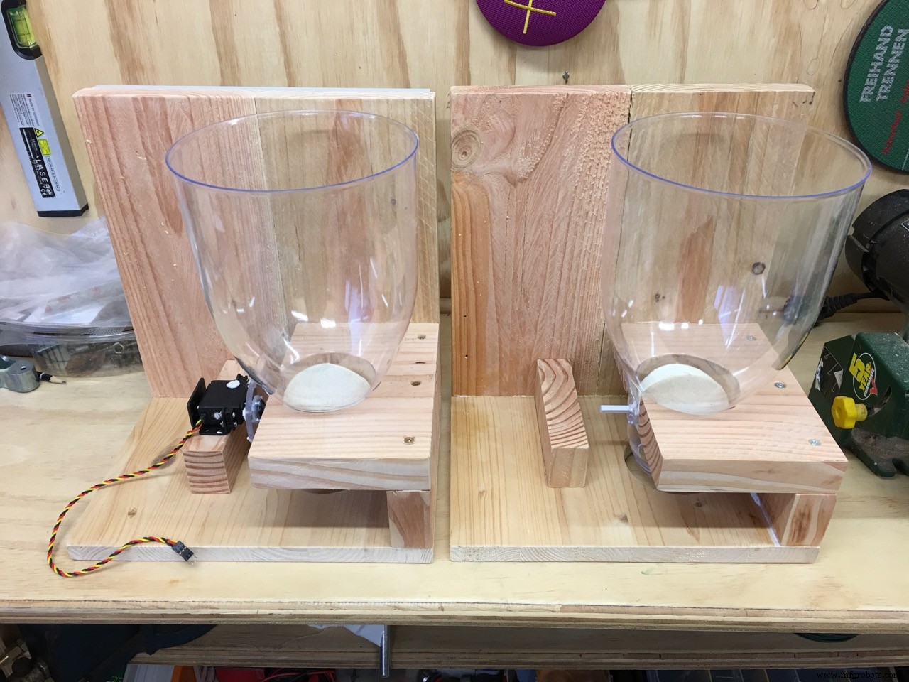


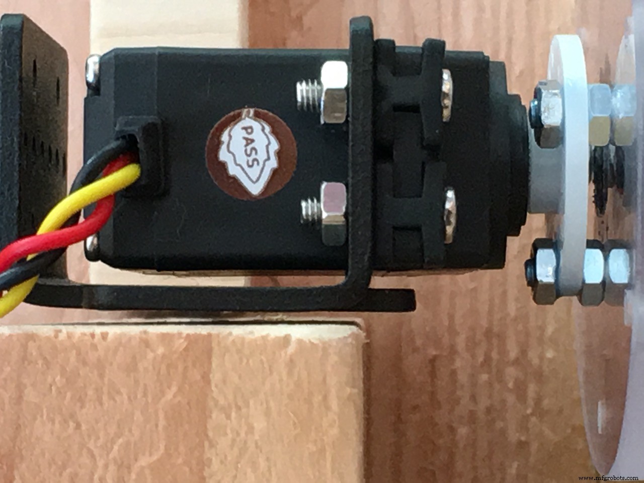
El servo y su conexión a la rueda de paletas del dispensador
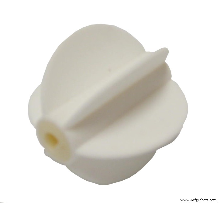
Asegúrate de comprar un buen servo. Primero compré un servo MG996R que modifiqué para rotación continua pero fue un desperdicio de dinero... Luego conseguí unos de calidad, en mi caso el Servo HSR-2645CRH.
¡TIENE QUE SER un modelo de rotación continua!! No intentes modificar un servo normal como hice yo. No funcionó casi lo suficiente y al parar no era inmediato.
Video de la prueba del servo: haz clic AQUÍ
La conexión del servo a la rueda de paletas del dispensador
Así que la pregunta era: ¿cómo conectar el servo a la rueda de paletas del comedero? Al principio parecía la parte más difícil del proyecto pero de hecho era muy simple.
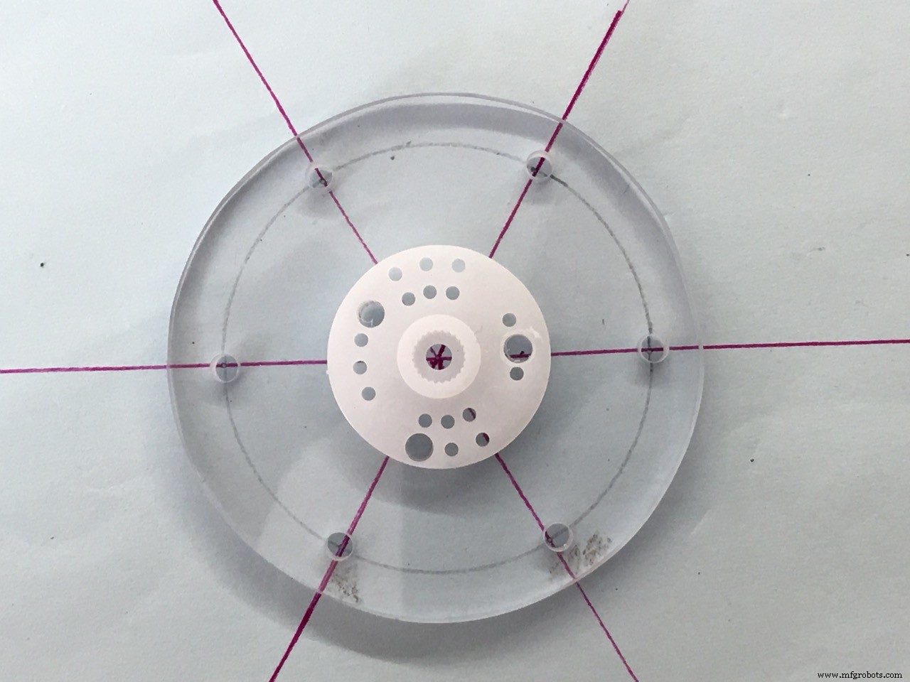
Tomé un trozo de policarbonato de 5mm y con una sierra de calar corté un disco redondo de unos 6 cm. En el centro taladré un agujero de 8 mm (el grosor del eje del comedero. Este eje plástico es extraíble de la rueda de paletas).
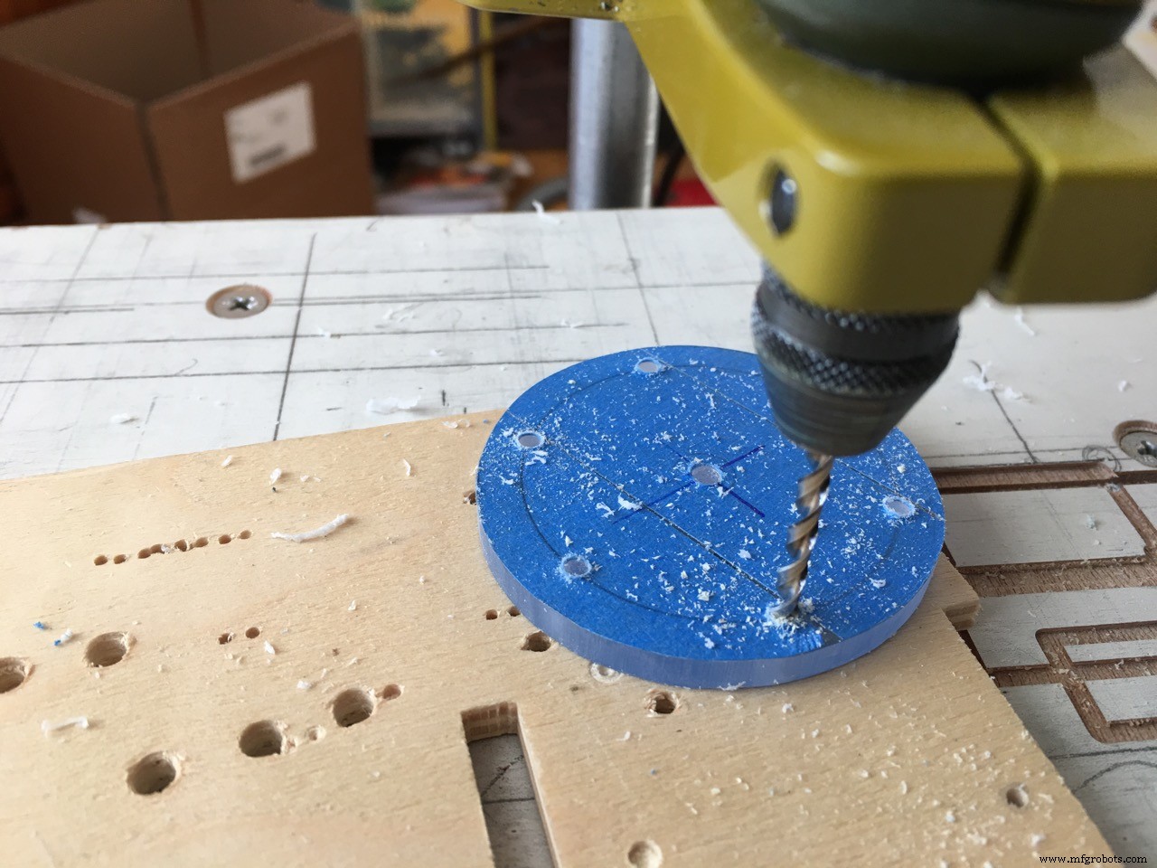
En el exterior taladré 6 agujeros de 3 mm, el grosor de los imanes. Estos se usan para dar al Arduino retroalimentación sobre la posición de la rueda de paletas del comedero.
Como la rueda de paletas tenía 6 paletas de goma, usé 6 imanes y los distribuí alrededor del borde del disco de policarbonato. 360 grados divididos por 6 son 60 grados. Los imanes de varilla encajarán perfectamente.
El sensor Hall detectará cada uno de los 6 imanes, así que podemos usar esa información para posicionar y detener la rueda de paletas con precisión. La variable de tiempo de parada del servo se usa para añadir un retraso después de alimentar, antes de detener el servo. Así con este retraso puedes ajustar la posición exacta de la rueda de paletas. Esto es importante porque si la posición de 'parada' es incorrecta, la comida no saldrá completamente de la rueda de paletas. También la posición del sensor Hall puede ser diferente en tu caso. Ajustar la variable de tiempo de parada del servo resolverá esto.
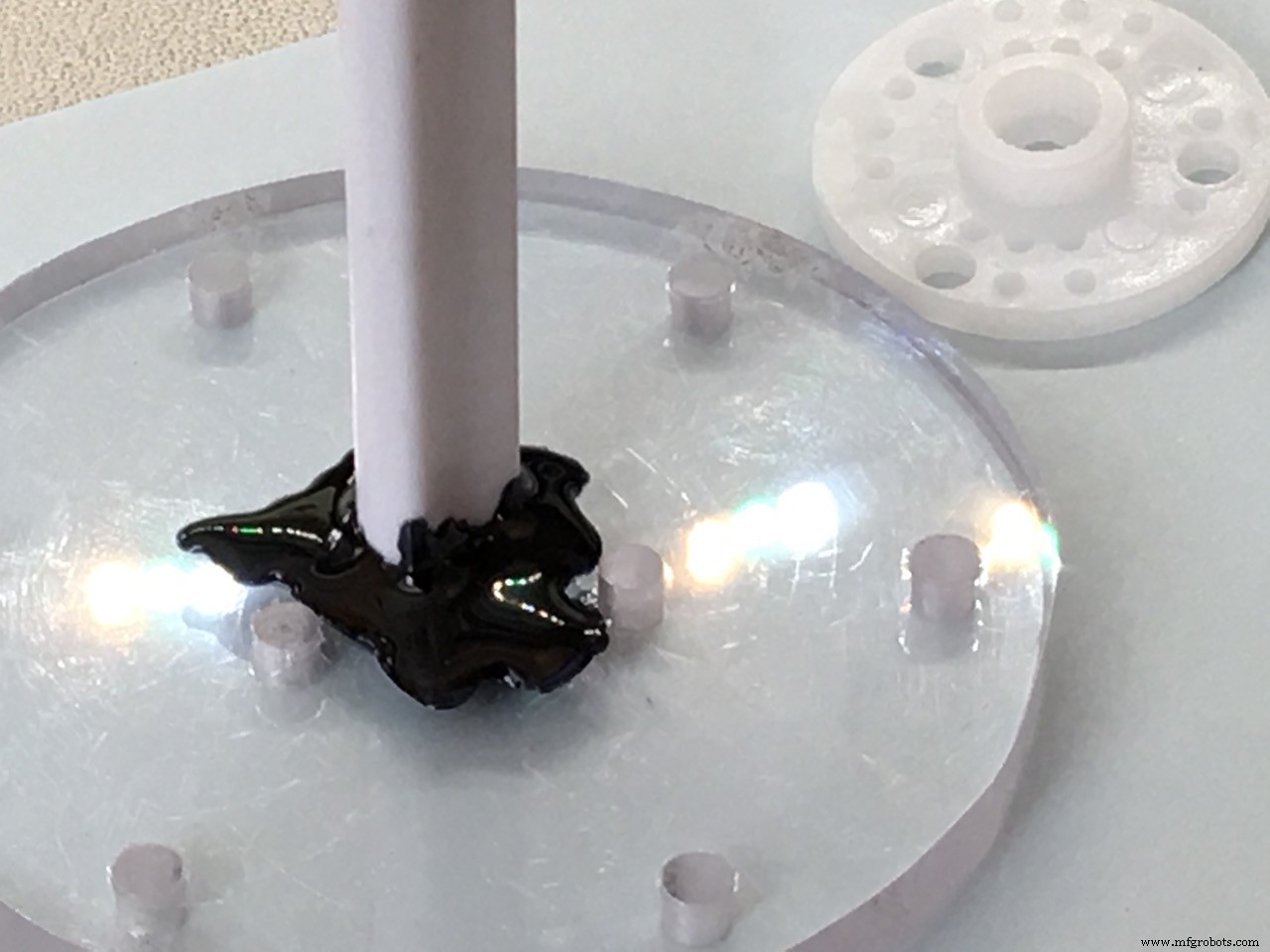
Ahora podemos pegar el eje de la rueda de paletas en el disco de policarbonato.


El cuerno de servo redondo blanco está atornillado en el disco de policarbonato con 3 tornillos M3. Usa algunas tuercas extra como separadores y ¡no aprietes demasiado!
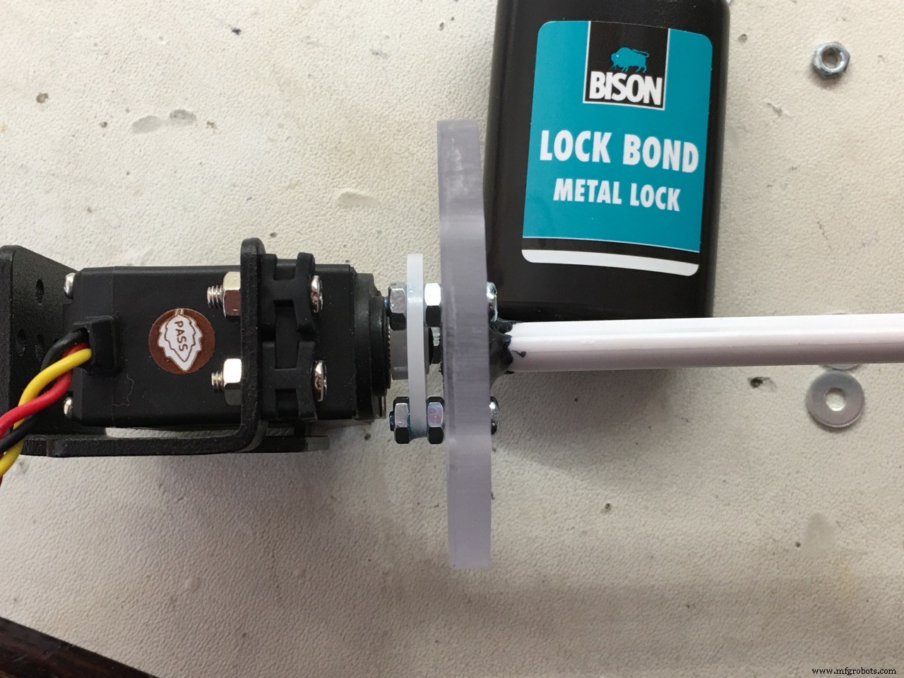


Ahora el servo es parte del conjunto del comedero, así que podemos ponerlo en el soporte de madera y medir qué tan alto tiene que ser el trozo de madera debajo del servo.


El sensor Hall
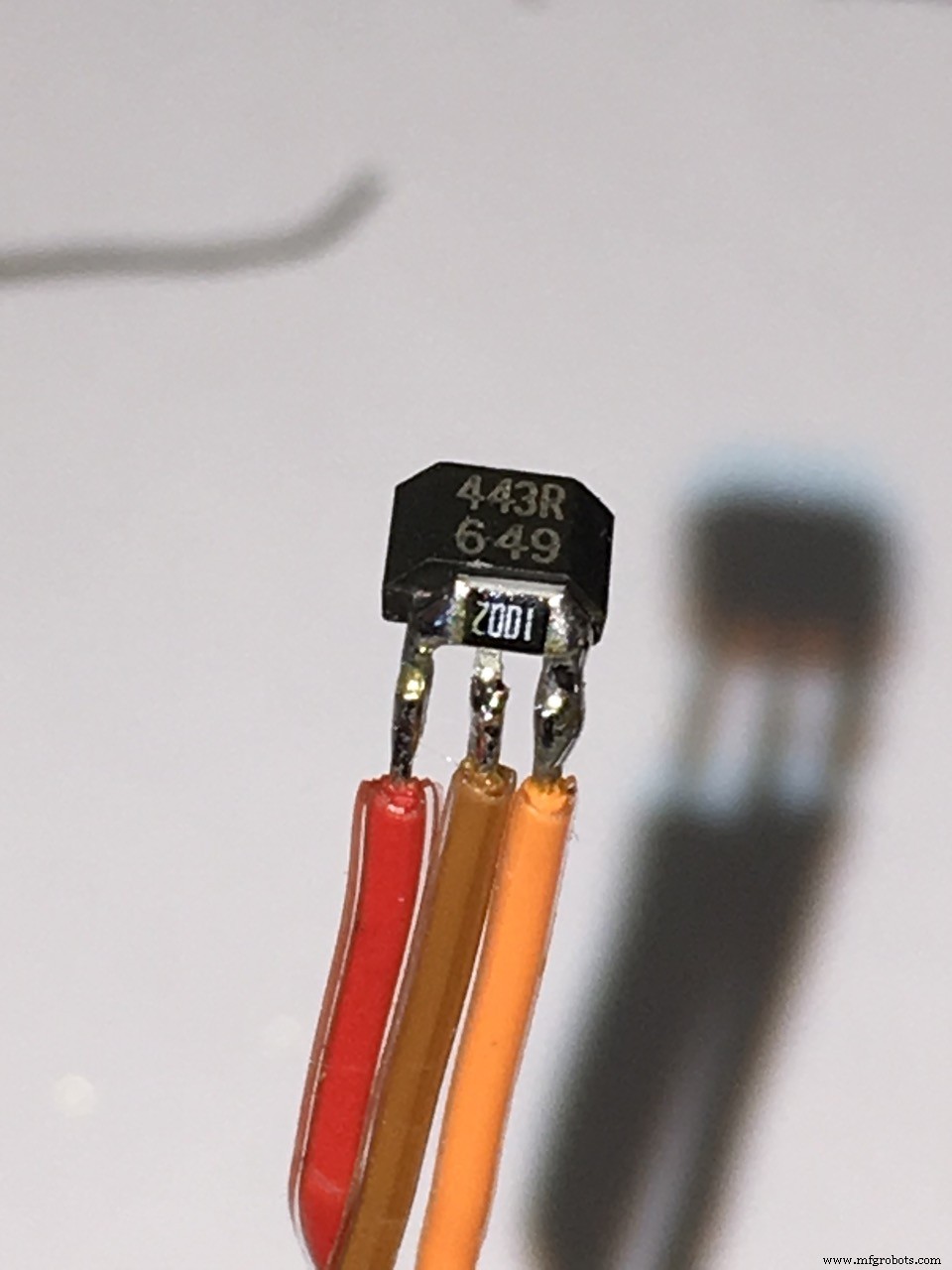
El sensor Hall que usé es del tipo UNIPOLAR. Dará una salida BAJA si un imán está cerca y NO necesita la polaridad inversa del imán para restablecer la salida a ALTA de nuevo. Así que usa un sensor Hall unipolar, mucho más fácil.
!!! El sensor Hall necesita una resistencia pull-up de 10KΩ.
Coloqué una resistencia SMD 0805 justo encima del sensor Hall, pero puedes hacerlo a tu manera. ¡No olvides esta resistencia!
Luego tomé un bolígrafo viejo y usé el plástico como soporte para el sensor.


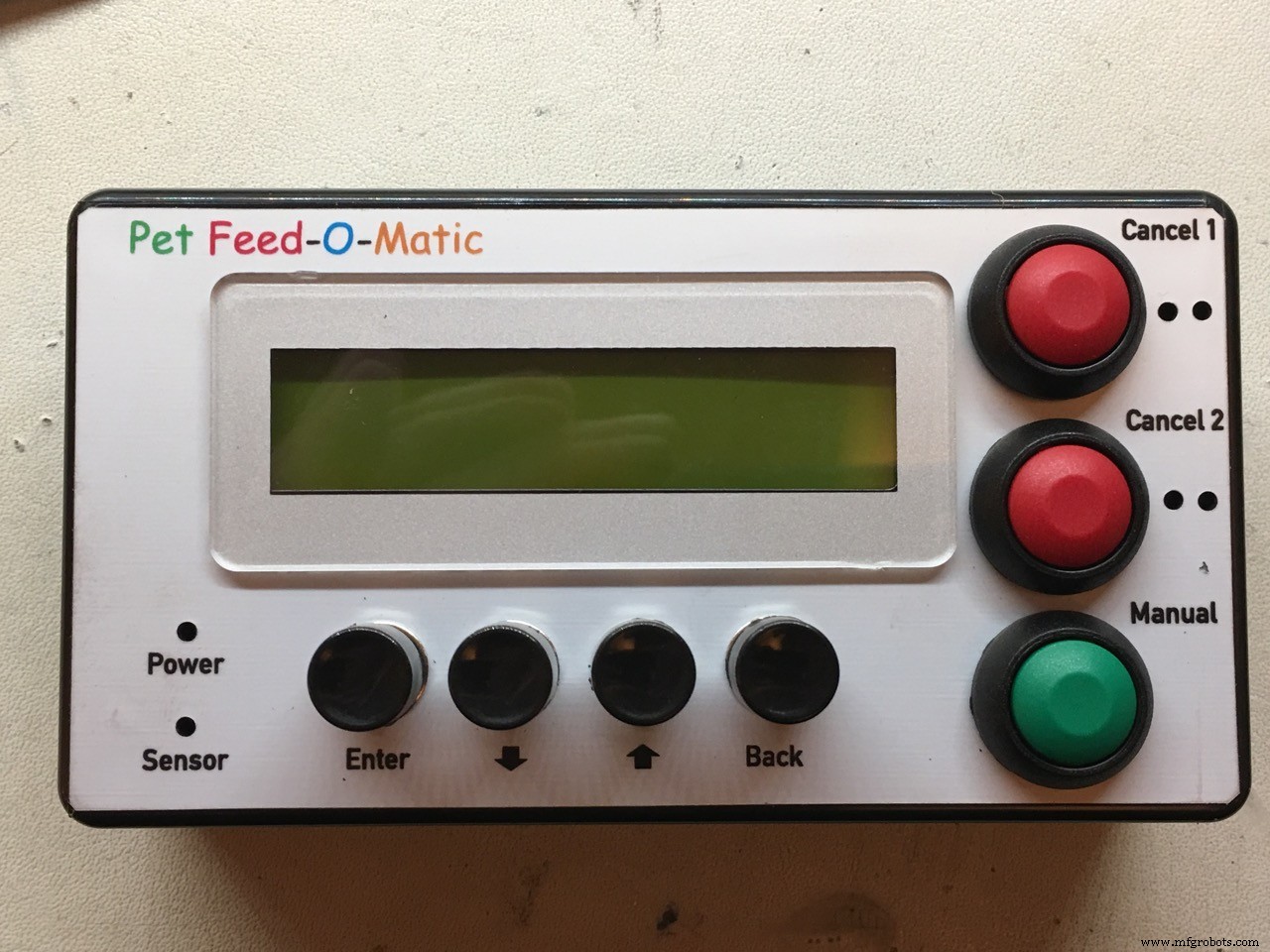
La carcasa de la electrónica
Usé una carcasa ABS Hammond con brida. 120 x 65 x 40 mm


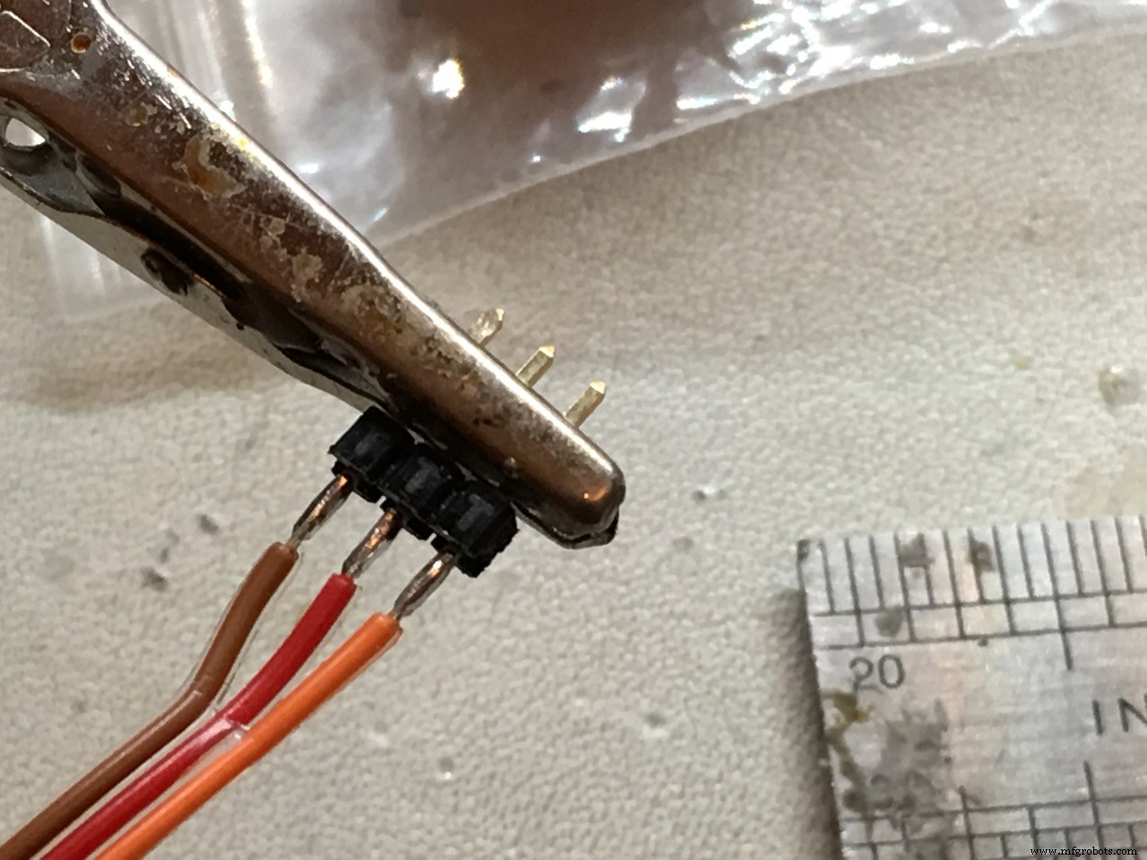
Para las conexiones externas usé conectores hembra de precisión, no los baratos chinos. Los uso mucho en todos mis proyectos. Nada peor que malas conexiones causando fallos (difíciles de encontrar).



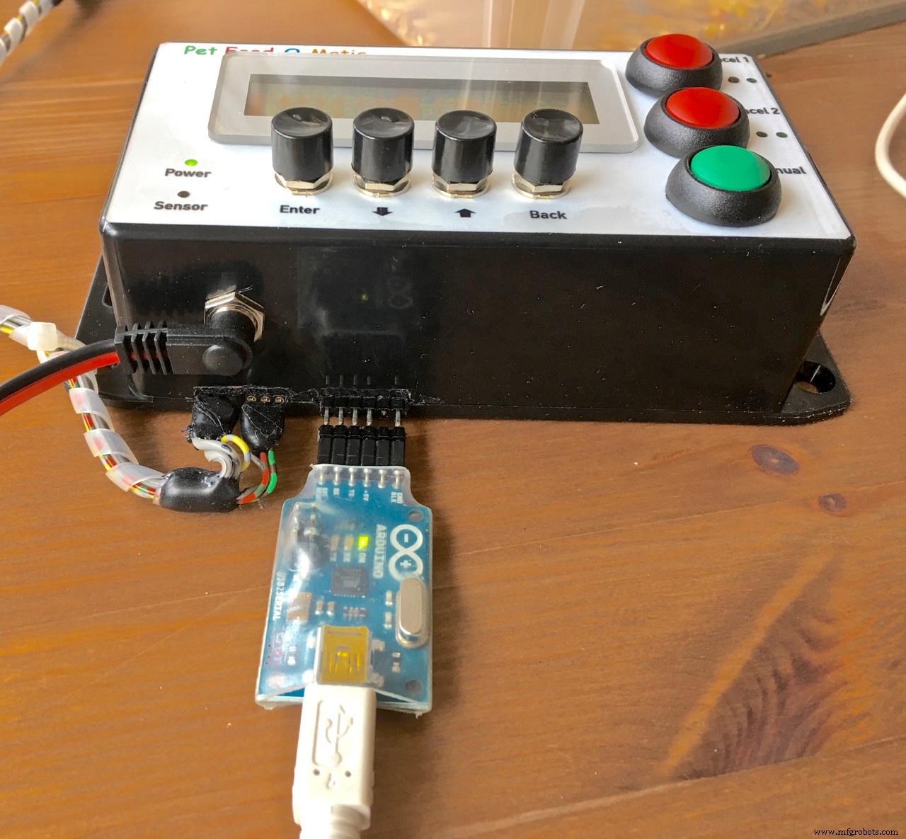
Para facilitar la programación del Arduino, tengo una conexión FTDI externa:

El panel frontal
Intenté muchas formas de hacer un panel frontal barato y bonito...
Primero usé Mod Podge para pegar una impresión láser en papel en el frontal de la carcasa y cubrirlo con más Mod Podge. --> FALLO
Luego probé un barniz transparente, basado en dispersión de poliuretano acrílico. Muy duradero y fuerte cuando se seca. Pegué el papel muy bien en la carcasa y barnizar la parte superior de la impresión del panel frontal se veía muy bien PERO no se adhería a las partes de tóner de la impresión láser. --> FALLO
Después de eso, tomé la impresión láser del panel frontal y solo laminé la parte superior con PVC de laminar. Acabado muy bonito, protegiendo el frontal y realzando los colores bellamente. Luego otra vez, pegué el papel laminado en la carcasa con el barniz. Mi idea era que el barniz permearía el papel haciéndolo resistente al agua. Pero como usé papel grueso eso no funcionó y al mojarlo para probar la resistencia al agua, el papel se curvó separándose de la carcasa. --> PARCIALMENTE FALLO, por investigar más.
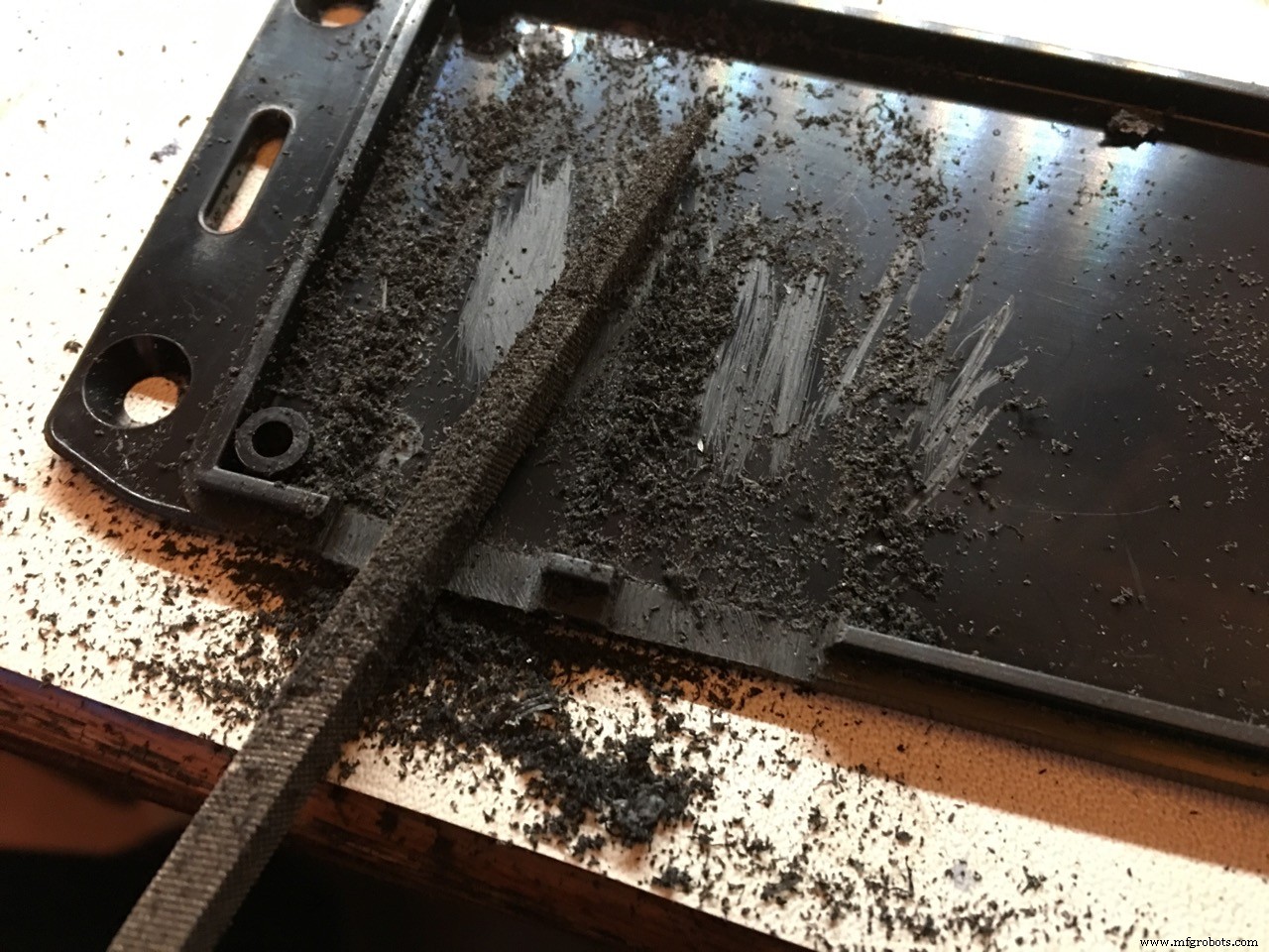
Otro intento: compré papel de aluminio especial, hecho para impresión láser. 2,25 euros por hoja. El resultado fue genial pero quería proteger el tóner con un film transparente especial. Eso no tuvo éxito porque no pude eliminar las imperfecciones como se ve en la foto 1:
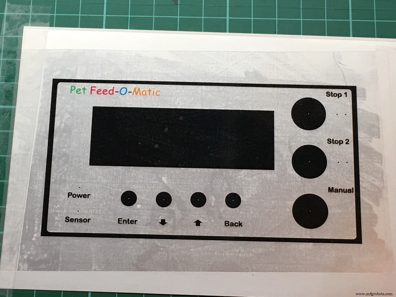
Luego otro intento de proteger con el barniz transparente, ¡Hizo el papel de aluminio muy brillante! PERO... de nuevo, el barniz no se adhería al tóner, así que renuncié al barniz permanentemente...
FINALMENTE... usé la impresión en papel de aluminio sin protección... Mostrará huellas dactilares cuando se manipule a menudo (mira debajo del botón BACK de la foto al principio de la página, la carcasa en el pienso de pollo) así que no es ideal pero aún bastante bueno para mí.
No se permiten más fotos aparentemente así que...
Eso es todo, amigos... ¡que lo disfrutéis!
Código
- Pet Feed-O-Matic v 1.1 - 20-02-2018
Pet Feed-O-Matic v 1.1 - 20-02-2018Arduino
v 1.1: pulsar los botones Cancel1 o 2 mostrará una explicación
// c++ stuff...
//#include <Arduino.h>
//#line 1
//#line 1 "/Users/Erik/Documents/PlatformIO/Projects/180202-151127-uno/src/Pet_Feeder_1_1_ENG.cpp"
/*
 _ _ /\ | | (_) / \ _ __ __| |_ _ _ _ __ ___ / /\ \ | '__/ _` | | | | | '_ \ / _ \ / ____ \| | | (_| | |_| | | | | | (_) | /_/ \_\_| \__,_|\__,_|_|_| |_|\___/ _____ _ ______ _ | __ \ | | | ____| | | | |__) |__| |_ | |__ ___ ___ __| | ___ _ __ | ___/ _ \ __| | __/ _ \/ _ \/ _` |/ _ \ '__| | | | __/ |_ | | | __/ __/ (_| | __/ | |_| \___|\__| |_| \___|\___|\__,_|\___|_|
Erik de Ruiter
-----------------------------------------------------------------------------
To do:
- remote feeding?
- feeder stop delay as menu editable item
last change: martes 20 febrero 2018 - 17:20:28
FEATURES:
- *Accurate portions* each time! (by using a Hall sensor)
- Two feeding times, once a day
- *Extremely* accurate Real Time Clock (Only with genuine DS3231 chip)
- Cancel upcoming feeding individually for both timers with display and Led indicator. Automatically reset after time has passed.
- Manual feed function (one portion per button press)
- Adjustable portions for each of the two feeding times (1-9 portions)
- Overview of all set parameters in the main screen
- Easy to navigate menu system
- LED indication if feeding was successful
- LCD backlight timer (off after 30 sec, on with any button press)
- Backup in the event of a failing Hall sensor
- Hass sensor LED will blink until midnight if the Hall sensor has failed
- Time and other settings are safely stored in EEPROM
WEBSITES:
LCD HD44780 character generator website to make your own lcd symbols
https://omerk.github.io/lcdchargen/
Arduino sketch Large letter comment generator
https://patorjk.com/software/taag/#p=display&c=c%2B%2B&f=Big&t=Comment
Revisions:
domingo 28 enero 2018 - 20:17:10
*/
////////////////////////////////////////////////////////////////////////////////
// USER CHANGEABLE VARIABLES
////////////////////////////////////////////////////////////////////////////////
// used for the Hall sensor fail backup function.
// the interval time should be somewhat larger than one 60 degree
// turn of the feeder (one portion)
#define HALL_SENSOR_BACKUP_VALUE 300
// delay before stopping the feeder servo after feeding. This way you can
// let the rotating peddle wheel stop at the right position
#define FEEDER_STOP_DELAY 100
// lcd backlight on time after pressing a button
#define LCD_BACKLIGHT_ON_TIME 30000
// exit menu without save after amanout of time set here in ms
#define MENU_TIMEOUT_VALUE 7000
////////////////////////////////////////////////////////////////////////////////
// https:// github.com/fdebrabander/Arduino-LiquidCrystal-I2C-library
#include <LiquidCrystal_I2C.h>
// https:// github.com/JChristensen/Button
#include <Button.h>
// https:// github.com/JChristensen/DS3232RTC
#include <DS3232RTC.h>
// https:// www.arduino.cc/playground/Code/Time
#include <Time.h>
// https:// arduino.cc/en/Reference/Wire (included with Arduino IDE)
#include <Wire.h>
#include <EEPROM.h>
// CONNECTIONS:
//
// LCD (I2C module):
// SCL - A5
// SDA - A4
// VCC
// GND
// interrupt hal sensor pin
#define HALL_SENSOR_PIN 3
#define BUTTON_BACK_PIN 4
#define BUTTON_UP_PIN 5
#define BUTTON_DOWN_PIN 6
#define BUTTON_SELECT_PIN 7
#define BUTTON_CANCEL1_PIN 8
#define BUTTON_CANCEL2_PIN 9
#define BUTTON_MANUAL_PIN 10
#define LED_CANCEL1_PIN A0
#define LED_CANCEL2_PIN A1
#define LED_SUCCESS1_PIN A2
#define LED_SUCCESS2_PIN A3
// feeder Servo output Pin
#define SERVO_OUTPUT_PIN 12
// Hall sensor input Pin
#define LED_HALL_SENSOR_PIN 13
// address LCD(16x2) 0x27 or 0x3F
LiquidCrystal_I2C lcd(0x3F, 16, 2);
// define button library settings
// A debounce time of 20 milliseconds usually works well
// for tactile button switches.
#define DEBOUNCE_MS 20
// ms required before repeating on long press
#define REPEAT_FIRST 1000
// repeat interval for long press
#define REPEAT_INCR 200
// To keep things simple, we use the Arduino's internal pullup resistor.
#define PULLUP true
#define INVERT true
// Declare the buttons
Button buttonSelect (BUTTON_SELECT_PIN, PULLUP, INVERT, DEBOUNCE_MS);
Button buttonUp (BUTTON_UP_PIN, PULLUP, INVERT, DEBOUNCE_MS);
Button buttonDown (BUTTON_DOWN_PIN, PULLUP, INVERT, DEBOUNCE_MS);
Button buttonBack (BUTTON_BACK_PIN, PULLUP, INVERT, DEBOUNCE_MS);
Button buttonCancel1 (BUTTON_CANCEL1_PIN, PULLUP, INVERT, DEBOUNCE_MS);
Button buttonCancel2 (BUTTON_CANCEL2_PIN, PULLUP, INVERT, DEBOUNCE_MS);
Button buttonManual (BUTTON_MANUAL_PIN, PULLUP, INVERT, DEBOUNCE_MS);
// The number that is adjusted
int count;
// Previous value of count (initialized to ensure it's different when
// the sketch starts)
int lastCount = -1;
// A variable time that is used to drive the repeats for long presses
unsigned long rpt = REPEAT_FIRST;
// used for the menu time-out
unsigned long timeoutValue = 0;
// manual cancel feeding times variables
boolean manualCancelFeed1 = false;
boolean manualCancelFeed2 = false;
// Manaual feed option
boolean manualFeed = false;
// Feed amount (in portions)
int feedAmount1 = 1;
int feedAmount2 = 1;
bool feederSuccess = false;
// feeder portions
int portions = 0;
int turns = 0;
// input actions
enum {btnSELECT, btnUP, btnDOWN, btnBACK, btnCANCEL1, btnCANCEL2, btnMANUAL, trigTIMEOUT};
// States of the Finite State Machine (FSM)
enum STATES { MAIN, MENU_EDIT_FEEDTIME1, MENU_EDIT_FEEDTIME2, MENU_EDIT_FEEDAMOUNT, MENU_EDIT_TIME, MENU_EDIT_DATE, MENU_EDIT_SETTINGS, EDIT_FEED_TIME1_HOUR, EDIT_FEED_TIME1_MINUTE, EDIT_FEED_TIME1_ON_OFF, EDIT_FEED_TIME2_HOUR, EDIT_FEED_TIME2_MINUTE, EDIT_FEED_TIME2_ON_OFF, EDIT_FEED_AMOUNT1, EDIT_FEED_AMOUNT2, EDIT_HOUR, EDIT_MINUTE, EDIT_DAY, EDIT_MONTH, EDIT_YEAR, EDIT_SERVO_STOP_DELAY, EDIT_SERVO_BACKUP_DELAY, };
// Holds the current state of the system
STATES state;
int8_t userInput;
int8_t trigger;
int Second;
int Minute;
int Hour;
int Day;
int Month;
int Year;
int8_t DoW;
String day_of_week;
unsigned char address, data;
int testt = 0;
int feed_time1_hour;
int feed_time1_minute;
bool feed_time1_active = false;
bool alarm1Activated = false;
int feed_time2_hour;
int feed_time2_minute;
bool feed_time2_active = false;
bool alarm2Activated = false;
// used for the blink funtion when editing values
uint32_t blink_interval = 500;
uint32_t blink_previousMillis = 0;
uint32_t blink_currentMillis = 0;
boolean blink_state = false;
// used for the blink funtion when editing values
uint32_t spinningWheel_interval = 170;
uint32_t spinningWheel_previousMillis = 0;
uint32_t spinningWheel_currentMillis = 0;
int spinningWheelSymbol = 0;
// used for the Hall sensor fail backup function
// the interval time should be somewhat larger than one 60 degree
// turn of the feeder (one portion).
uint32_t hallSensorBackup_interval = HALL_SENSOR_BACKUP_VALUE;
uint32_t hallSensorBackup_currentMillis = 0;
boolean hallSensorFail = false;
// used for the lcd backlight timer
uint32_t lcdBacklight_interval = LCD_BACKLIGHT_ON_TIME;
uint32_t lcdBacklight_currentMillis = 0;
boolean RTC_error = true;
boolean long_press_button = false;
// Define custom symbols for the LCD display
byte bell_symbol_Char[8] = { B00100, B01110, B01110, B01110, B11111, B00100, B00000, B00000 };
byte inverted_one_Char[8] = { 0b11111, 0b11011, 0b10011, 0b11011, 0b11011, 0b11011, 0b10001, 0b11111 };
byte inverted_two_Char[8] = { 0b11111, 0b11011, 0b10101, 0b11101, 0b11011, 0b10111, 0b10001, 0b11111 };
byte arrow_up_Char[8] = { 0b00100, 0b01110, 0b11111, 0b01110, 0b01110, 0b01110, 0b01110, 0b00000 };
byte arrow_down_Char[8] = { 0b00000, 0b01110, 0b01110, 0b01110, 0b01110, 0b11111, 0b01110, 0b00100 };
byte inverted_p_Char[8] = { 0b11111, 0b10001, 0b10101, 0b10001, 0b10111, 0b10111, 0b11111, 0b00000 };
byte backslash_Char[8] = { 0b00000, 0b10000, 0b01000, 0b00100, 0b00010, 0b00001, 0b00000, 0b00000 };
byte thickDash_Char[8] = { 0b00000, 0b00000, 0b11111, 0b11111, 0b11111, 0b00000, 0b00000, 0b00000 };
volatile boolean hallSensorActivated = false;
// Interrupt 1
void HallSensorIsr() {
  hallSensorActivated = true;
  // turn on Hall sensor LED
  digitalWrite(LED_HALL_SENSOR_PIN, HIGH);
}
// These lines are needed to make this sketch a C++ file.
// I use it because I edit the code with the Atom
// text editor and the PlatformIO add-on
void HallSensorIsr();
void setup();
void loop();
void change_states();
void check_inputs();
void transition(int trigger);
void check_alarm();
void check_manual_feed();
void display_menu_option_set_feedtime1();
void display_menu_option_set_feedtime2();
void display_menu_option_set_feed_amount();
void display_menu_option_set_time();
void display_menu_option_set_date();
void midnight_reset();
void display_time();
void displayFeedingAmouts();
void displayFeedingTimes();
void set_feedAmount();
void set_time();
void set_date();
void set_feeding1_time();
void set_feeding2_time();
void get_time();
void get_date();
void write_time();
void write_date();
void write_feeding_time1();
void write_feeding_time2();
void write_feedamount();
void get_feedamount();
void get_feed_time1();
void get_feed_time2();
void check_RTC();
byte decToBcd(byte val);
byte bcdToDec(byte val);
void leading_zero(int digits);
void blinkFunction();
void displaySpinningWheel();
void startFeederServo();
void stopFeederServo();
void activateFeeder(int portions);
void check_LcdBacklight();
void lcd_backlight_ON();
void ledsAndLcdDisplayStartup();
void hallSensorCheck();
#line 355
// ******************************************************************************
// SETUP
void setup() {
  // activate the lcd screen
  lcd.begin();
  // turn lcd backlight on and start backlight off-timer
  lcd_backlight_ON();
  // start I2C
  Wire.begin();
  // hall sensor input to detect rotation of the feeder/feed amount output check pin
  pinMode(HALL_SENSOR_PIN, INPUT_PULLUP);
  pinMode(LED_HALL_SENSOR_PIN, OUTPUT);
  pinMode(SERVO_OUTPUT_PIN, OUTPUT);
  pinMode(LED_CANCEL1_PIN, OUTPUT);
  pinMode(LED_CANCEL2_PIN, OUTPUT);
  pinMode(LED_SUCCESS1_PIN, OUTPUT);
  pinMode(LED_SUCCESS2_PIN, OUTPUT);
  // set default state of LED's to OFF
  digitalWrite(LED_CANCEL1_PIN, LOW);
  digitalWrite(LED_CANCEL2_PIN, LOW);
  digitalWrite(LED_SUCCESS1_PIN, LOW);
  digitalWrite(LED_SUCCESS2_PIN, LOW);
  digitalWrite(LED_HALL_SENSOR_PIN, LOW);
  lcd.createChar(0, thickDash_Char);
  lcd.createChar(1, bell_symbol_Char);
  lcd.createChar(2, backslash_Char);
  lcd.createChar(3, inverted_p_Char);
  lcd.createChar(4, inverted_one_Char);
  lcd.createChar(5, inverted_two_Char);
  lcd.createChar(6, arrow_up_Char);
  lcd.createChar(7, arrow_down_Char);
  // set feeder Servo to default state OFF
  stopFeederServo();
  Wire.begin();
  // set RTC as the Syncprovider
  setSyncProvider(RTC.get);
  // time in sec of resync with RTC
  setSyncInterval(60);
  // Disable the default square wave of the SQW pin.
  RTC.squareWave(SQWAVE_NONE);
  // Attach an interrupt on the Hall sensor (when unput turns LOW)
  // ever 60 degree turn of the feeder shaft, the hall sensor
  // should generate an interrupt
  attachInterrupt(INT1, HallSensorIsr, FALLING);
  // display test
  ledsAndLcdDisplayStartup();
  // Initial state of the FSM
  state = MAIN;
  // read the stored alarm value from the Arduino memory
  get_feed_time1();
  get_feed_time2();
}// End SETUP
// ******************************************************************************
// LOOP
void loop() {
  // change states of FSM
  change_states();
  // check inputs (buttons)
  check_inputs();
  // check if alarm was called
  check_alarm();
  // check if manual feed was requsted
  check_manual_feed();
  // at midnight, reset some variables
  midnight_reset();
  // check connection RTC
  check_RTC();
  // Check the Hall sensor function
  hallSensorCheck();
  // check if lcd backlight must be turned off
  check_LcdBacklight();
}// End of LOOP
// ******************************************************************************
// ******************************************************************************
// ******************************************************************************
// ******************************************************************************
//******************************************************************************
// Finite State Machine
void change_states() {
  // states
  switch (state) {
  //---------------------------------------
  case MAIN:
    display_time();
    displayFeedingAmouts();
    displayFeedingTimes();
    break;
  //---------------------------------------
  case MENU_EDIT_FEEDTIME1:
    display_menu_option_set_feedtime1();
    break;
  //---------------------------------------
  case MENU_EDIT_FEEDTIME2:
    display_menu_option_set_feedtime2();
    break;
  //---------------------------------------
  case MENU_EDIT_FEEDAMOUNT:
    display_menu_option_set_feed_amount();
    break;
  //---------------------------------------
  case MENU_EDIT_TIME:
    display_menu_option_set_time();
    break;
  //---------------------------------------
  case MENU_EDIT_DATE:
    display_menu_option_set_date();
    break;
  //---------------------------------------
  case EDIT_FEED_TIME1_HOUR:
    set_feeding1_time();
    break;
  //---------------------------------------
  case EDIT_FEED_TIME1_MINUTE:
    set_feeding1_time();
    break;
  //---------------------------------------
  case EDIT_FEED_TIME1_ON_OFF:
    set_feeding1_time();
    break;
  //---------------------------------------
  case EDIT_FEED_TIME2_HOUR:
    set_feeding2_time();
    break;
  //---------------------------------------
  case EDIT_FEED_TIME2_MINUTE:
    set_feeding2_time();
    break;
  //---------------------------------------
  case EDIT_FEED_TIME2_ON_OFF:
    set_feeding2_time();
    break;
  //---------------------------------------
  case EDIT_FEED_AMOUNT1:
    set_feedAmount();
    break;
  //---------------------------------------
  case EDIT_FEED_AMOUNT2:
    set_feedAmount();
    break;
  //---------------------------------------
  case EDIT_HOUR:
    set_time();
    break;
  //---------------------------------------
  case EDIT_MINUTE:
    set_time();
    break;
  //---------------------------------------
  case EDIT_DAY:
    set_date();
    break;
  //---------------------------------------
  case EDIT_MONTH:
    set_date();
    break;
  //---------------------------------------
  case EDIT_YEAR:
    set_date();
    break;
  //---------------------------------------
  }
}
//******************************************************************************
// Check INPUTS
void check_inputs() {
  // first check if timeout has occurred
  if ( millis() - timeoutValue > MENU_TIMEOUT_VALUE ) {
    userInput = trigTIMEOUT;
    transition(userInput);
  }
  // check state of buttons
  buttonSelect.read();
  buttonUp.read();
  buttonDown.read();
  buttonBack.read();
  buttonManual.read();
  buttonCancel1.read();
  buttonCancel2.read();
  // check manual cancel Feed1 button
  switch (buttonCancel1.wasPressed()) {
  case 1:
    // invert variable value (true to false and vise versa)
    manualCancelFeed1 = !manualCancelFeed1;
    //turn on lcd backlight manually
    lcd_backlight_ON();
    // message when Cancel1 button is pressed
    if (manualCancelFeed1 == 1) {
      lcd.clear();
      lcd.setCursor(0, 0);
      // 0123456789012345 - LCD screen character counter
      lcd.print("Upcoming Feed #1");
      lcd.setCursor(0, 1);
      lcd.print("cancelled once ");
      delay(2000);
      lcd.clear();
    } else if (manualCancelFeed1 == 0) {
      lcd.clear();
      lcd.setCursor(0, 0);
      // 0123456789012345 - LCD screen character counter
      lcd.print("Upcoming Feed #1");
      lcd.setCursor(0, 1);
      lcd.print("canceling undone");
      delay(2000);
      lcd.clear();
    }
    break;
  }
  // check manual cancel Feed2 button
  switch (buttonCancel2.wasPressed()) {
  case 1:
    // invert variable value (true to false and vise versa)
    manualCancelFeed2 = !manualCancelFeed2;
    //turn on lcd backlight manually
    lcd_backlight_ON();
    // message when Cancel1 button is pressed
    if (manualCancelFeed2 == 1) {
      lcd.clear();
      lcd.setCursor(0, 0);
      // 0123456789012345 - LCD screen character counter
      lcd.print("Upcoming Feed #2");
      lcd.setCursor(0, 1);
      lcd.print("cancelled once ");
      delay(2000);
      lcd.clear();
    } else if (manualCancelFeed2 == 0) {
      lcd.clear();
      lcd.setCursor(0, 0);
      // 0123456789012345 - LCD screen character counter
      lcd.print("Upcoming Feed #2");
      lcd.setCursor(0, 1);
      lcd.print("canceling undone");
      delay(2000);
      lcd.clear();
    }
    break;
  }
  // check manual Feed button
  switch (buttonManual.wasPressed()) {
  case 1:
    manualFeed = true;
    //turn on lcd backlight manually
    lcd_backlight_ON();
    break;
  }
  // check MENU/SELECT button
  switch (buttonSelect.wasPressed()) {
  case 1:
    userInput = btnSELECT;
    //turn on lcd backlight manually
    lcd_backlight_ON();
    transition(userInput);
    break;
  }
  // check UP button
  switch (buttonUp.wasPressed()) {
  case 1:
    userInput = btnUP;
    transition(userInput);
    //turn on lcd backlight manually
    lcd_backlight_ON();
    break;
  }
  // check long press UP button
  switch (buttonUp.wasReleased()) {
  case 1:
    long_press_button = false;
    rpt = REPEAT_FIRST;
    break;
  }
  switch (buttonUp.pressedFor(rpt)) {
  case 1:
    // increment the long press interval
    rpt += REPEAT_INCR;
    long_press_button = true;
    userInput = btnUP;
    transition(userInput);
    break;
  }
  // check DOWN button
  switch (buttonDown.wasPressed()) {
  case 1:
    userInput = btnDOWN;
    transition(userInput);
    //turn on lcd backlight manually
    lcd_backlight_ON();
    break;
  }
  // check long press DOWN button
  switch (buttonDown.wasReleased()) {
  case 1:
    long_press_button = false;
    rpt = REPEAT_FIRST;
    break;
  }
  switch (buttonDown.pressedFor(rpt)) {
  case 1:
    // increment the long press interval
    rpt += REPEAT_INCR;
    long_press_button = true;
    userInput = btnDOWN;
    transition(userInput);
    break;
  }
  // check btnBACK button
  switch (buttonBack.wasPressed()) {
  case 1:
    userInput = btnBACK;
    transition(userInput);
    //turn on lcd backlight manually
    lcd_backlight_ON();
    break;
  }
}
//******************************************************************************
// Check for state transition trigger
void transition(int trigger) {
  switch (state) {
  //---------------------------------------
  case MAIN:
    // set time-out timr
    timeoutValue = millis();
    if (trigger == btnSELECT) {
      lcd.clear();
      state = MENU_EDIT_FEEDTIME1;
    } else if (trigger == btnBACK) {
      //lcd.clear();
      //state = ALARM1_AND_2_TIME;
    }
    break;
  //---------------------------------------
  case MENU_EDIT_FEEDTIME1:
    // set time-out timer
    timeoutValue = millis();
    // check for time-out 'button' trigger
    if (trigger == trigTIMEOUT) {
      lcd.clear();
      state = MAIN;
    }
    // Now check for button triggers
    if (trigger == btnUP) {
      //no action, this is the first menu
    } else if (trigger == btnDOWN) {
      lcd.clear();
      state = MENU_EDIT_FEEDTIME2;
    }
    if (trigger == btnSELECT) {
      lcd.clear();
      state = EDIT_FEED_TIME1_HOUR;
    }
    if (trigger == btnBACK) {
      lcd.clear();
      state = MAIN;
    }
    break;
  //---------------------------------------
  case MENU_EDIT_FEEDTIME2:
    // set time-out timer
    timeoutValue = millis();
    // check for time-out 'button' trigger
    if (trigger == trigTIMEOUT) {
      lcd.clear();
      state = MAIN;
    }
    // Now check for button triggers
    if (trigger == btnUP) {
      lcd.clear();
      state = MENU_EDIT_FEEDTIME1;
    } else if (trigger == btnDOWN) {
      lcd.clear();
      state = MENU_EDIT_FEEDAMOUNT;
    }
    if (trigger == btnSELECT) {
      lcd.clear();
      state = EDIT_FEED_TIME2_HOUR;
    }
    if (trigger == btnBACK) {
      lcd.clear();
      state = MAIN;
    }
    break;
  //---------------------------------------
  case MENU_EDIT_FEEDAMOUNT:
    // set time-out timer
    timeoutValue = millis();
    // check for time-out 'button' trigger
    if (trigger == trigTIMEOUT) {
      lcd.clear();
      state = MAIN;
    }
    // Now check for button triggers
    if (trigger == btnUP) {
      lcd.clear();
      state = MENU_EDIT_FEEDTIME2;
    } else if (trigger == btnDOWN) {
      lcd.clear();
      state = MENU_EDIT_TIME;
    }
    if (trigger == btnSELECT) {
      lcd.clear();
      state = EDIT_FEED_AMOUNT1;
    }
    if (trigger == btnBACK) {
      lcd.clear();
      state = MAIN;
    }
    break;
  //---------------------------------------
  case MENU_EDIT_TIME:
    // set time-out timer
    timeoutValue = millis();
    // check for time-out 'button' trigger
    if (trigger == trigTIMEOUT) {
      lcd.clear();
      state = MAIN;
    }
    // Now check for button triggers
    if (trigger == btnUP) {
      lcd.clear();
      state = MENU_EDIT_FEEDTIME2;
    }
    if (trigger == btnDOWN) {
      lcd.clear();
      state = MENU_EDIT_DATE;
    }
    if (trigger == btnSELECT) {
      lcd.clear();
      state = EDIT_HOUR;
    }
    if (trigger == btnBACK) {
      lcd.clear();
      state = MAIN;
    }
    break;
  //---------------------------------------
  case MENU_EDIT_DATE:
    // set time-out timer
    timeoutValue = millis();
    // check for time-out 'button' trigger
    if (trigger == trigTIMEOUT) {
      lcd.clear();
      state = MAIN;
    }
    // Now check for button triggers
    if (trigger == btnUP) {
      lcd.clear();
      state = MENU_EDIT_TIME;
    } else if (trigger == btnDOWN) {
      //no action, end of menu items!
    }
    if (trigger == btnSELECT) {
      lcd.clear();
      state = EDIT_DAY;
    }
    if (trigger == btnBACK) {
      lcd.clear();
      state = MAIN;
    }
    break;
  //---------------------------------------
  case EDIT_FEED_TIME1_HOUR:
    // set time-out timer
    timeoutValue = millis();
    // check for time-out 'button' trigger
    if (trigger == trigTIMEOUT) {
      lcd.clear();
      state = MAIN;
    }
    // Now check for button triggers ... Este archivo ha sido truncado, por favor descárgalo para ver su contenido completo.
  }
}
Esquemas
Comedero para mascotas basado en Arduino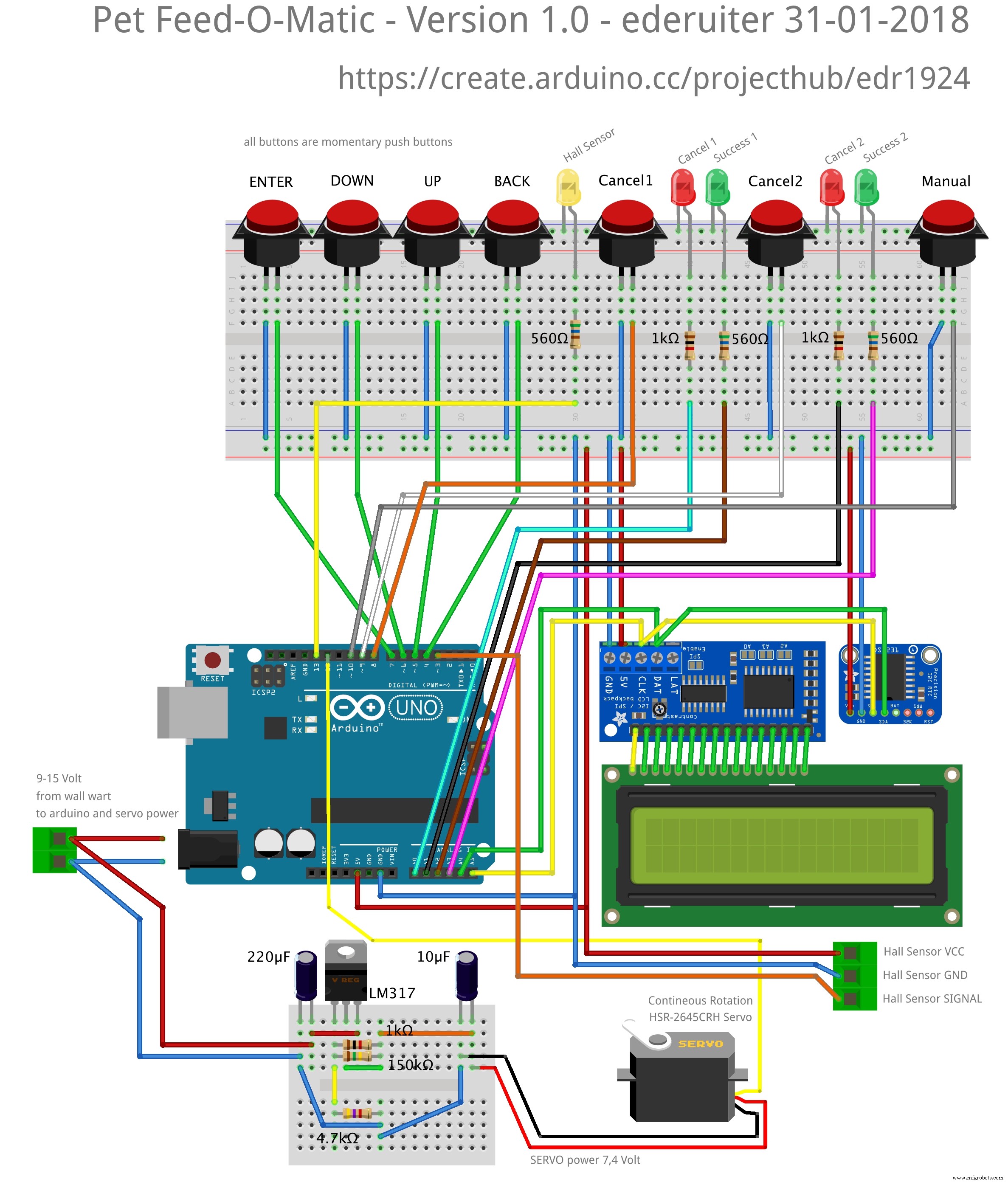 Usé Arduino IDE 1.8.2. ¡TEN CUIDADO DE NO TENER DOS VERSIONES DE LAS MISMAS LIBRERÍAS EN TU CARPETA DE LIBRERÍAS!
arduino_pet_feeder_final_eng_v1_0-ino_hex_libraries_dsoo0HscCr.zip
Proceso de manufactura
- Producción de Alimentos para Mascotas: De Ingredientes a Regulación – Guía Completa
- Construye una consola de control DIY para Photoshop con Arduino Nano RP2040
- Construye un Spybot controlado por Bluetooth con Arduino
- Vestido Inteligente con Arduino Nano: Monitor de Ritmo Cardíaco y LEDs Controlados por CrazyCircuits y DFRobot
- Construye un juego Tetris con Arduino Nano en matriz LED 16x8 DIY
- Construye tu Propio Tamagotchi con Arduino: Mascota Digital DIY
- Controla Dos Motores Paso a Paso con Arduino Nano y Joystick - Tutorial Sencillo
- Comedero Automático para Mascotas Controlado por IR: Guía DIY con Arduino
- Contador Geiger Portátil con Arduino Nano: Construye tu Detector de Radiación
- Pantalla TFT Shield de Alto Rendimiento 2.8” para Arduino Nano – Display SPI 320×240
- Comedero Inteligente para Mascotas Impreso en 3D con Arduino Nano