



Reloj LED con Arduino y RTC en tiempo real: Construye una pantalla horaria fiable
Componentes y suministros
| Arduino UNO | ×1 |
| Módulo RTC (DS1307) | ×1 |
| Resistencia 1k Ω | ×15 |
| Resistencia 120 Ω | ×15 |
| Regulador lineal 7805 | ×1 |
| Condensador 22 pF | ×1 |
| Cristal 16 MHz | ×1 |
| Condensador 10 µF | ×1 |
| Pila botón CR2032 + porta-pilas | ×1 |
| LED verde 5 mm | ×190 |
| Transistor NPN (RF) | ×10 |
| Transistor PNP uso general | ×12 |
| Pulsador táctil | ×4 |
| Fuente 12V 5A (60W) | ×1 |
Herramientas necesarias
- Soldador y estaño sin plomo
- Multímetro digital
Sobre el proyecto
Primero descarga las librerías necesarias:
Wire.h(incluida en Arduino IDE)RTClib.h(librería Adafruit para DS1307)
Ver el video

Módulo RTC

Circuito Arduino

Conexiones RTC

Interruptores RTC

Identificar Ánodo y Cátodo

Diagrama de circuito (ÁNODO COMÚN)

Si usas LED CÁTODO COMÚN, haz estos cambios

Fuente de alimentación

Código
Código del reloj LED (Arduino)
Descarga y sube este código al proyecto. Incluye multiplexado de 6 dígitos 7 segmentos, lectura RTC DS1307 por I2C, ajuste horario mediante pulsadores, formato 12/24h configurable y salida de onda cuadrada 1Hz en pin SQW.
/* Reloj 4 dígitos 7 segmentos - Modificado por niq_ro y BMIAK Basnayaka */
#include
#include "RTClib.h"

RTC_DS1307 RTC;

// Pines segmentos
int segA = 0, segB = 1, segC = 2, segD = 4, segE = 7, segF = 8, segG = 12, segDP = 13;
// Pines dígitos (multiplexado)
int digit1 = 11, digit2 = 10, digit3 = 9, digit4 = 6, digit5 = 5, digit6 = 3;

// Pulsadores
byte SW0 = A0, SW1 = A2, SW2 = A1, SWT = A3;
int Adhr=0, Admnt=0, D=0, Z=0;
long zh, uh, ore, zm, um, miniti;

void setup() {
  Wire.begin(); RTC.begin();
  // RTC.adjust(DateTime(F(__DATE__), F(__TIME__))); // Descomenta para poner hora
  // Configurar SQW 1Hz
  Wire.beginTransmission(0x68);
  Wire.write(0x07); Wire.write(0x10); Wire.endTransmission();

  pinMode(segA, OUTPUT); pinMode(segB, OUTPUT); pinMode(segC, OUTPUT);
  pinMode(segD, OUTPUT); pinMode(segE, OUTPUT); pinMode(segF, OUTPUT);
  pinMode(segG, OUTPUT); pinMode(segDP, OUTPUT);
  pinMode(digit1, OUTPUT); pinMode(digit2, OUTPUT); pinMode(digit3, OUTPUT);
  pinMode(digit4, OUTPUT); pinMode(digit5, OUTPUT); pinMode(digit6, OUTPUT);

  pinMode(SW0, INPUT_PULLUP); pinMode(SW1, INPUT_PULLUP);
  pinMode(SW2, INPUT_PULLUP); pinMode(SWT, INPUT_PULLUP);
  digitalWrite(segDP, LOW);
}

void loop() {
  DateTime now = RTC.now();
  long HR = now.hour()*1000;
  long timp = (HR*10)+now.minute()*100+now.second();
  Adhr = now.hour(); Admnt = now.minute();

  // Conmutador 12/24h
  if (digitalRead(SWT)==0){ delay(300); D = !D; }
  if (D == 0 && timp >= 130000) { timp -= 120000; digitalWrite(segDP, HIGH); }
  else digitalWrite(segDP, LOW);

  // Multiplexado 6 dígitos (HHMMSS)
  for(int i=100; i>0; i--) { if(timp>=100000) displayNumber01(timp); else displayNumber02(timp); }
  for(int i=100; i>0; i--) { if(timp>=100000) displayNumber03(timp); else displayNumber04(timp); }
  for(int i=100; i>0; i--) { if(timp>=100000) displayNumber05(timp); else displayNumber06(timp); }

  if (digitalRead(SW0)==0) { delay(100); Z=1; set_time(); }
}

void set_time() {
  byte hours=Adhr, minutes=Admnt;
  // ... (lógica completa de ajuste horario con pulsadores SW1/SW2, escritura RTC)
  // Incluye conversión BCD, límites 0-23h / 0-59m, guardado en DS1307
}

// Funciones displayNumber01..06 y lightNumber (multiplexado ánodo común)
// Definen SEGMENT_ON=HIGH, SEGMENT_OFF=LOW para ánodo común.
// Para cátodo común, invertir definiciones.
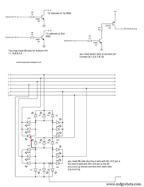
Esquemáticos
Cableado del display 7 segmentos con LEDs.
Soporte FPV de doble eje DIY: Tutorial con joystick y Arduino
Sistema de aparcamiento inteligente: Solución eficiente para aparcamiento urbano
Proceso de manufactura
- Reloj POV con Arduino: Construye una pantalla LED de persistencia de visión
- Reloj de Palabras DIY con Arduino: Construye una Pantalla Elegante en Tiempo Real
- Construya un osciloscopio Arduino de 20 kHz en LCD Nokia 5110: Guía DIY fácil
- Construye un Reloj Maestro LED Personalizado con Alarma – Visible desde 12 Metros
- Persianas Inteligentes: Control Automático de Luz con Arduino y Energía Solar
- Reloj de Palabras en Italiano con Arduino Nano, NeoPixel, LCD y RTC
- Controla un LED por Bluetooth con Arduino – Guía DIY paso a paso
- Construye un Robot Cuadrúpedo Inteligente con Arduino: Guía Paso a Paso
- Reloj Preciso de 7 Segmentos con Arduino Pro Mini y RTC DS1302
- Medidor kWh Sigfox Fiable con Arduino MKR Fox 1200
- Circuito de entrada analógica aislada para Arduino