


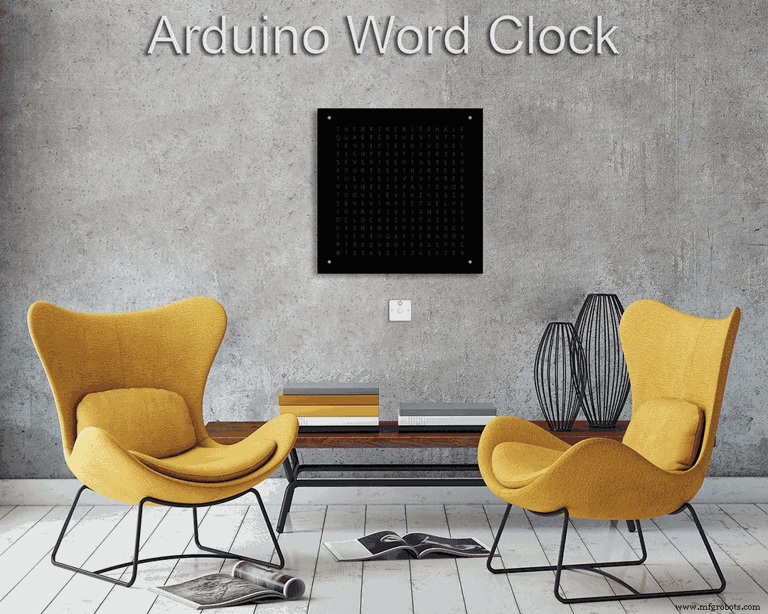
Word Clock con resolución de tiempo mínima en palabras
Componentes y suministros
 |
| × | 1 |
Acerca de este proyecto
Se pueden encontrar más detalles sobre esta compilación en mi sitio aquí:Word Clock
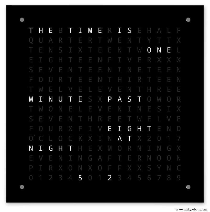
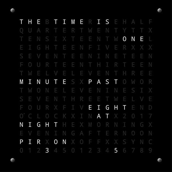
El reloj de palabras Arduino con resolución de minutos de tiempo en palabras y visualización lineal de segundos.
También hay modos para reloj digital, reloj analógico, temperatura y humedad, además de tres juegos:Game of Life, Simon y Tetris.
El reloj puede ser independiente o funcionar como esclavo de un reloj maestro si es necesario.
Sin un reloj maestro, el tiempo se controla mediante el reloj de tiempo real integrado con compensación de temperatura.
Hay una opción para el control de radar PIR o Doppler para que el reloj se apague automáticamente cuando no haya nadie en la habitación.
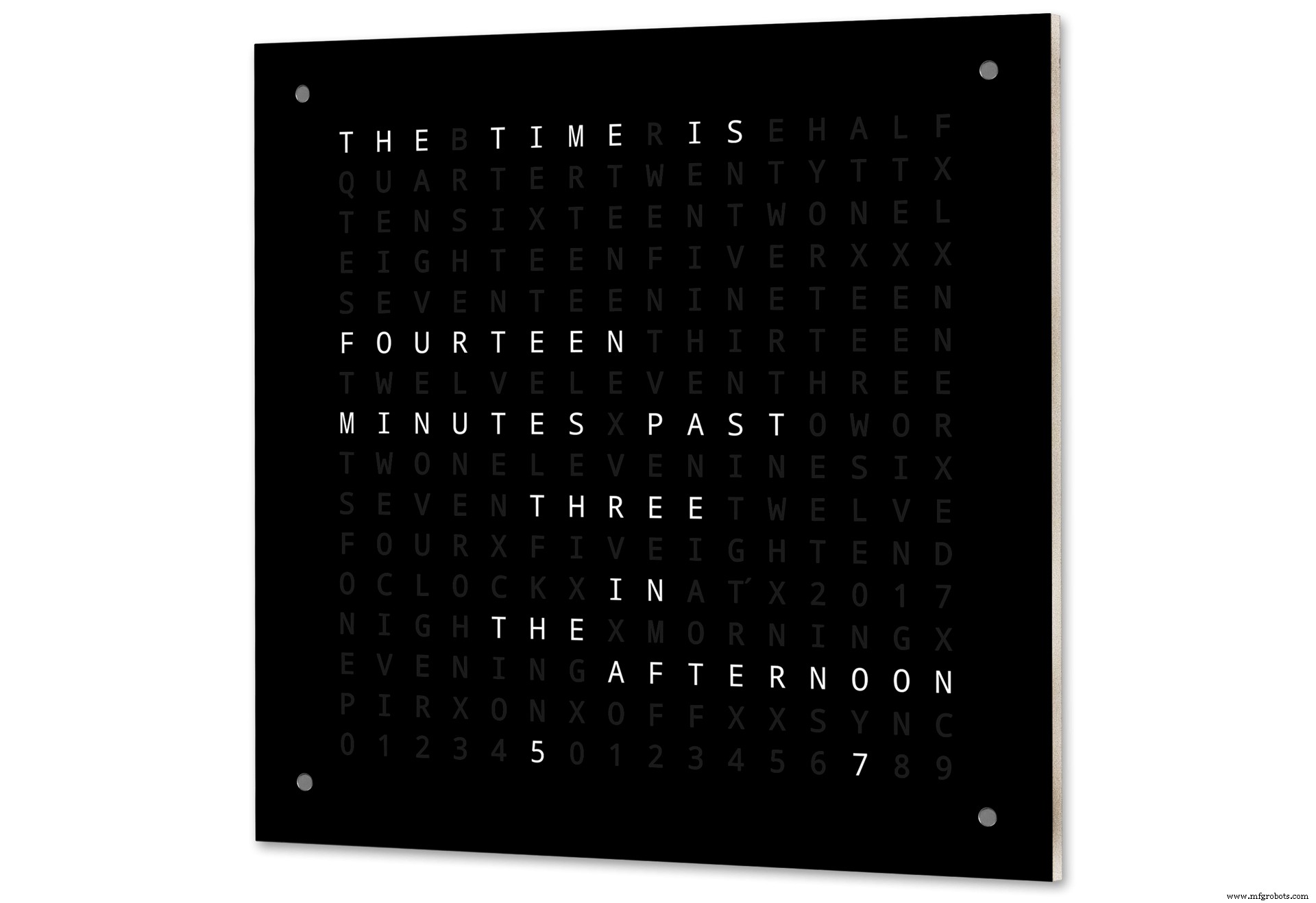
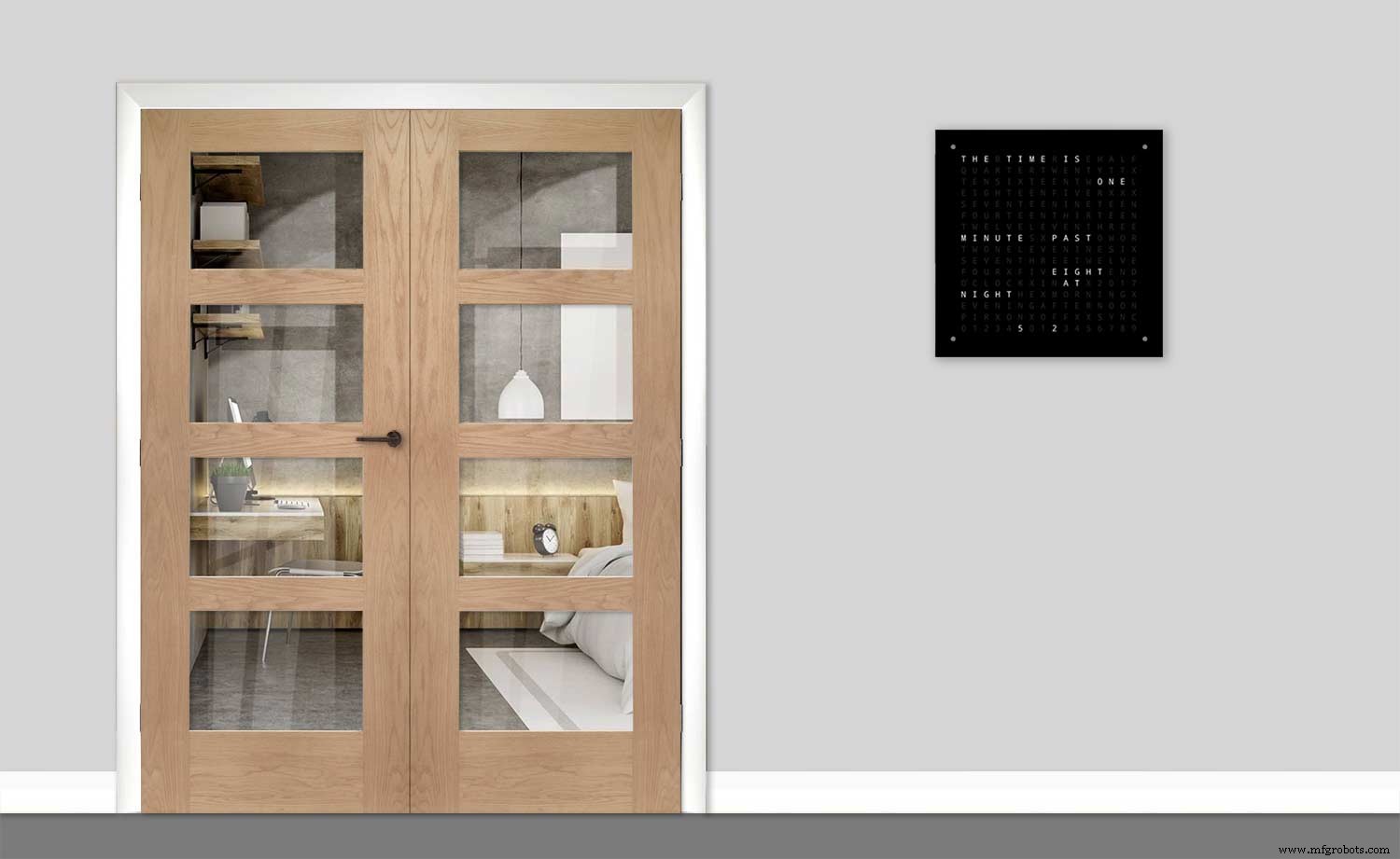
El reloj mide 500 mm x 500 mm (19,68 "x 19,68"), pesa 12 libras (5,5 kg) y está diseñado para montarse en la pared. Hay paneles táctiles en cada esquina para configurar y controlar el reloj.
Paso 1:Acerca de Word Clocks
Acerca de Word Clocks
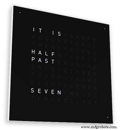
Los relojes de palabras indican la hora utilizando una matriz de palabras o números y letras y han existido durante muchos años. Hay algunos tipos de diseño diferentes que afectan la complejidad de la construcción del reloj.
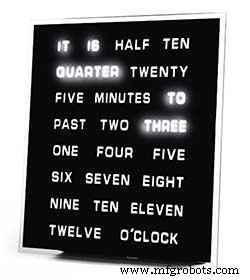
Los bloques de palabras más simples usan para decir la hora en una resolución de cinco minutos, por ejemplo, O'CLOCK, 5 PAST, 10 PAST, etc. Estos relojes solo usan 20 o más bloques LED individuales y, por lo tanto, son los más simples de construir. La principal desventaja de estos relojes es que solo pueden mostrar la hora en este formato establecido.
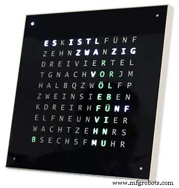
El reloj de nivel medio tiene una matriz de 11x10 LED más cuatro LED adicionales en la parte exterior del reloj. El reloj controlado por Raspberry Pi Photo 2 incluso tiene LED multicolores y, como tiene 110 LED individuales, puede mostrar dígitos e imágenes básicas. Estos relojes todavía usan una resolución de 5 minutos en palabras, pero a menudo agregan "acaba de pasar 5" o casi 10 "para aumentar ligeramente la resolución. A menudo, los cuatro LED alrededor de las esquinas del marco indican los cuatro minutos que pasan para llenar el espacio entre La resolución redactada de 5 minutos. Estos relojes son razonablemente complejos de construir y, a menudo, utilizan tiras de LED para facilitar la construcción.
Hay versiones comerciales de este tipo de reloj disponibles. La versión para colgar en la pared de 450 mm cuesta alrededor de £ 1000 y cuenta con paneles frontales intercambiables en muchos colores y materiales, así como también hay disponibles relojes y computadoras de escritorio más pequeñas.
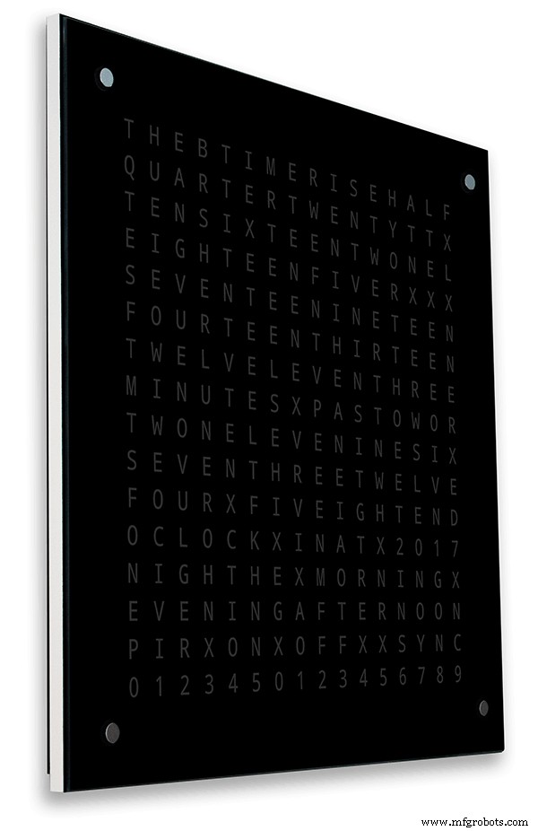
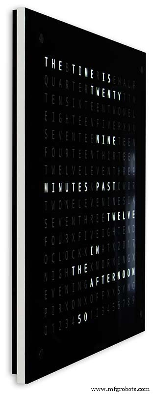
Reloj Word de 256 matrices de Wouter Devinck
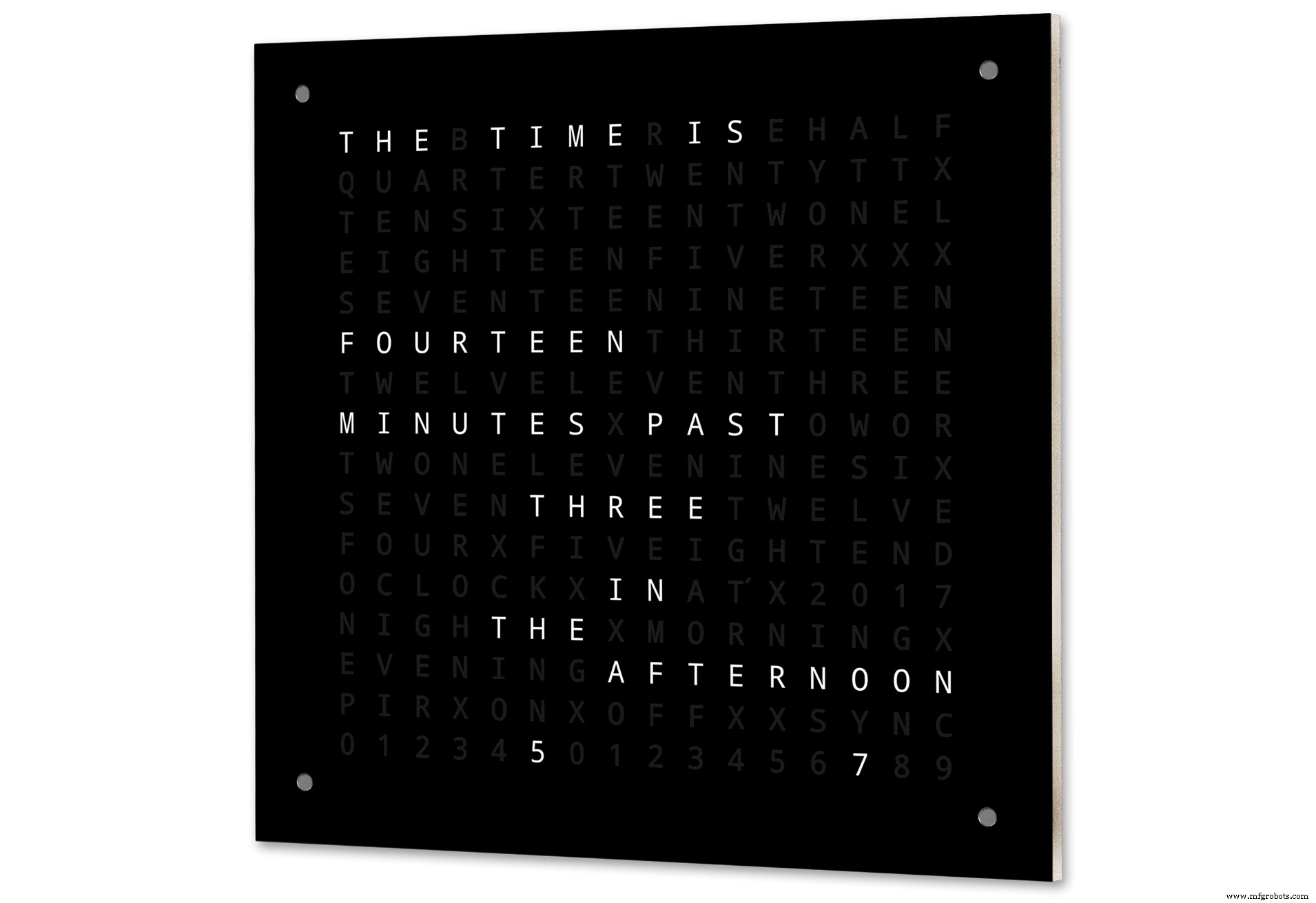
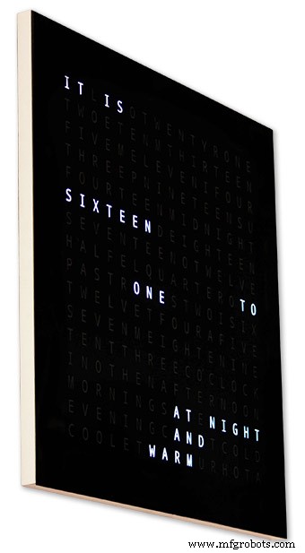
Los relojes de palabras con el nivel más alto de complejidad utilizan una matriz de LED de 16x16 que proporciona un total de 256 LED para controlar. Estos relojes tienen una resolución de tiempo redactada de un minuto, así como la mañana, la tarde, la noche, etc. A menudo indican la temperatura aproximada en palabras como cálido, muy cálido, frío muy frío, etc.
Con los 256 LED para jugar, hay una gran cantidad de modos de visualización diferentes disponibles. Estos relojes son bastante complejos de construir debido a la cantidad de conexiones en la pantalla matricial. La construcción de la matriz LED en PCB con componentes de montaje en superficie permite cuerpos de reloj muy delgados y simplifica la construcción de la pantalla, pero por encima de 500 mm x 500 mm, los PCB comienzan a ser costosos.
La construcción manual de la matriz de LED como en mi reloj necesita espacio y 500 mm x 500 mm es un buen punto de partida, ya que puede acomodar los grandes telares de cableado necesarios para interconectar los LED y los módulos de visualización. Se pueden construir relojes de pared muy grandes usando matrices LED construidas a mano.
Paso 2:cambios
Cambios
Este reloj es una mezcla del hardware Wouter Devinck Clock y el software de reloj Pijuana "catalán". No he usado ningún PCB, solo módulos listos para usar y tres pequeños circuitos de placa Vero para la alimentación.
Los principales cambios se detallan a continuación.
No se utilizan PCB personalizados en esta versión del reloj, solo es barato y fácil de conseguir mediante módulos preconstruidos.
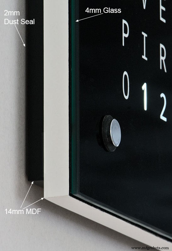
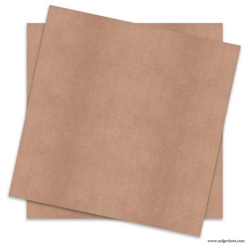
El cuerpo del reloj principal está construido con 2 hojas de MDF de 14 mm en lugar de una sola hoja de 18 mm.
La hoja posterior es 10 mm más pequeña que la hoja frontal en todos los lados excepto en la parte superior, por lo que el reloj parece tener solo 14 mm de grosor.
El reloj Wouter Devinck tiene solo 20 mm de profundidad, incluido el vidrio de 2 mm, mientras que mi reloj tiene en realidad 34 mm de profundidad, incluido el vidrio de 4 mm y el sello antipolvo de 2 mm en la parte trasera. Debido al retroceso del panel trasero de 14 mm y al retroceso de 1,5 mm del panel de vidrio desde la mayoría de los ángulos, el reloj solo parece 14 mm de profundidad. Esta profundidad adicional me ha permitido usar una matriz de LED y telares de cableado hechos a mano en lugar de 4 PCB grandes. También significa que puedo usar módulos prediseñados de fácil mantenimiento sin circuitos integrados de montaje en superficie en las placas MAX7219.
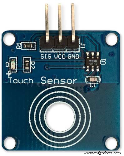
La pantalla principal está construida directamente en los LED de la pantalla sin PCB, por lo que es posible una pantalla de cualquier tamaño. Se utilizan módulos de sensor táctil TTP223 en lugar de Azoteq IQS127D montado en las placas principales.
Las placas de controlador de pantalla para el MAX7219 I / C utilizan placas de matriz de LED modificadas. Estas placas vienen completas con todos los componentes.
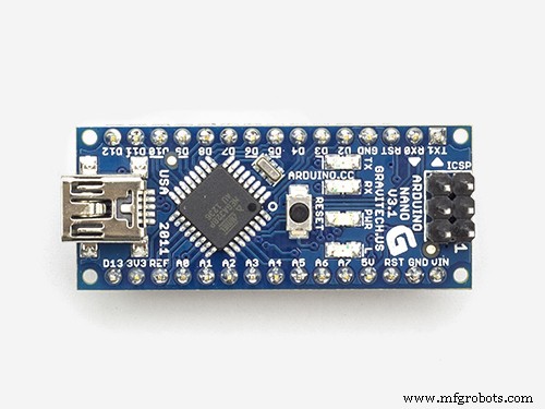
Se utiliza un Arduino Nano para impulsar el reloj debido a su pequeño tamaño.
Se utiliza un módulo de sensor PIR para apagar la pantalla cuando no hay nadie en la habitación (esto se puede desactivar para mantener la pantalla siempre encendida).
Se agrega una resistencia recortadora al circuito, accesible desde la parte inferior del reloj con un pequeño destornillador de punta plana para calibrar el brillo automático de la pantalla.
Sincronización con mi sistema de reloj maestro cada minuto en 30 segundos. Si no hay pulso de sincronización disponible, el reloj funcionará libremente usando el RTC. Los pulsos de sincronización se muestran en la pantalla principal.
El software se basa principalmente en la versión "catalana" de Pijuana del reloj de palabras, por lo que se ha traducido al inglés para la pantalla. Los créditos se muestran modificados de la versión "Catalana" Pijuana "para mostrar el número de versión actual del software, mi nombre y también el año de construcción.
La temperatura expresada se eliminó de la pantalla del reloj y se agregó una pantalla de segundos lineales a la fila inferior de los relojes Word, Digital y Analogue.
Cuando el PIR se enciende o apaga, se muestra "PIR ON" o "PIR OFF" durante unos segundos en la pantalla del reloj.
Este reloj utiliza un módulo de reloj de precisión en tiempo real DS3231 AT24C32 I2C según el reloj Wouter Devinck y el reloj Pijuana "catalán". No estoy interesado en utilizar la batería recargable de iones de litio que se suministra con el módulo. Utilizo una batería no recargable y modifiqué el módulo para adaptarlo.
El vidrio flotado de 4 mm con bordes pulidos reemplaza al vidrio de 2 mm. El vidrio se fija al tablero principal de MDF utilizando sujetadores Chicago en lugar de pegamento. Estos también actúan como almohadillas táctiles para controlar el reloj y permiten que el vidrio se pueda quitar si es necesario.
Hay dos sellos contra el polvo integrados en el reloj, uno en el panel trasero y otro detrás del panel de visualización de vidrio extraíble. En el modo de ajuste del reloj, al presionar el botón BOT Right ahora se restablecen los segundos a 0.
Se han realizado los siguientes cambios en la redacción en inglés para que la redacción sea como yo la diría. La forma en que las personas dicen la hora variará de una región a otra, dependiendo de dónde viva / haya ido a la escuela, etc.
Se eliminaron las palabras que indicaban la temperatura en el word clock. Estos han sido reemplazados con estado de sincronización, PIR ON / OFF y visualización lineal de segundos.
Se cambió "MINUTES" a "MINUTE" en 1 minuto pasado y 1 minuto a la hora.
Se agregó una "A" antes del "TRIMESTRE" pasado y un "TRIMESTRE" a la hora.
Se agregó el "ELEVEN" perdido del reloj de Wouter Devinck según sus notas.
Al mediodía cambió la hora para que diga DOCE EN LA TARDE.
A medianoche cambió la hora para que diga DOCE DE LA NOCHE. Después de la medianoche, el reloj siempre dirá EN LA MAÑANA.
El "O'CLOCK" ahora está sin puntuar y solo muestra OCLOCK.
Paso 3:Diseño de la carcasa
Como mi reloj no usa PCB de matriz de pantalla personalizados con componentes de montaje en superficie, la caja del reloj tiene que ser algo más profunda que el diseño de Wouter.
Mi caja tiene 34 mm de profundidad e incluye el sello antipolvo trasero de 2 mm, el tablero de MDF trasero de 14 mm, el tablero de visualización frontal de 14 mm y el vidrio flotado de 4 mm.
La caja derecha de Wouter tiene solo 21 mm de profundidad, un solo panel de MDF de 18 mm y vidrio flotado de 2 mm.
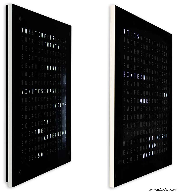
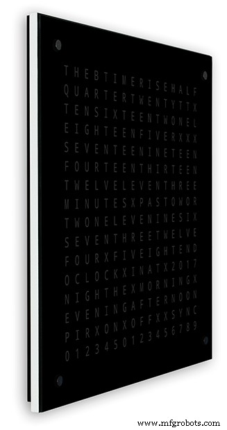
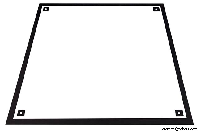
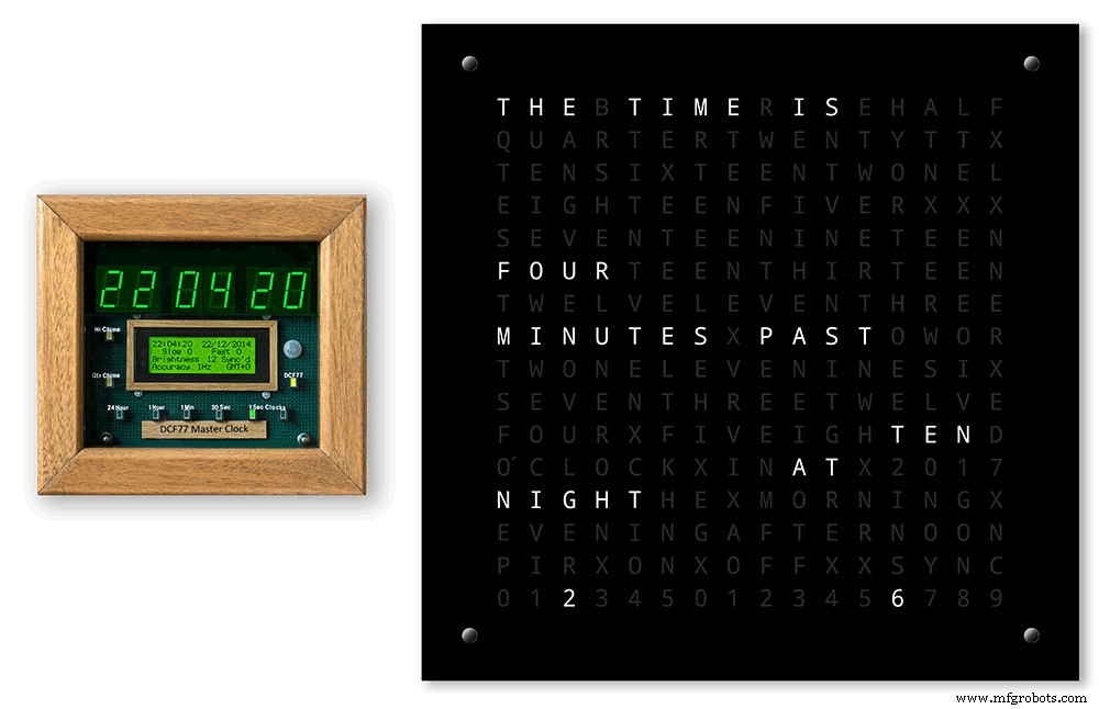
Para que mi reloj parezca menos voluminoso a la vista cuando se monta en la pared, he incorporado algunas características de diseño simples. La imagen de arriba muestra mi reloj a la izquierda y el reloj de Wouter a la derecha. Desde una vista de ángulo lateral extremo, puede ver claramente que mi estuche se ve más voluminoso.
Esto se compensa un poco porque la placa trasera es negra en lugar de blanca, lo que hace que su ojo se concentre en el delgado borde blanco de 14 mm. El tablero trasero es 10 mm más corto en la parte inferior y ambos lados refuerza esta ilusión.
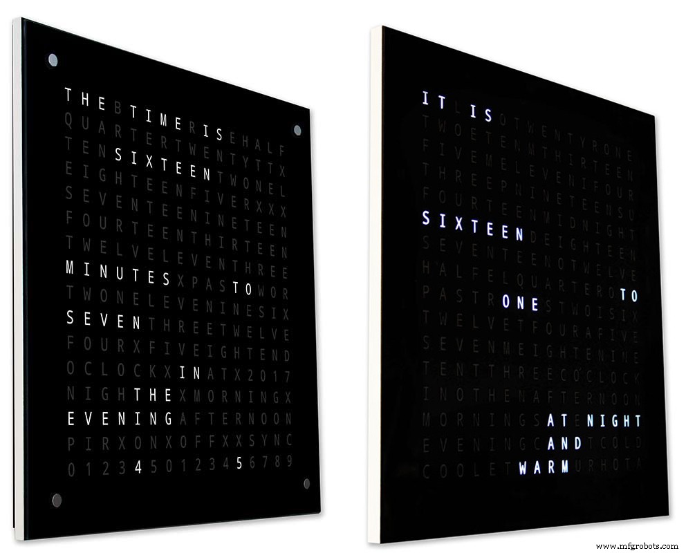
Arriba, de nuevo mi reloj a la izquierda y el reloj de Wouter a la derecha. Cuanto más hacia la parte delantera de los relojes te acercas, la placa trasera más corta de mi reloj desaparece de la vista hasta que solo se ve la placa frontal delgada de 14 mm. El vidrio de 4 mm también se corta 1-2 mm más corto que la placa frontal para ayudar a ocultarlo de la vista. . Mi voluminosa caja de reloj de 34 mm ahora parece tan delgada como la de Wouter.
Paso 4:Controles
Controles

Hay módulos de control táctil TTP223 en el reloj, en las esquinas superior izquierda, superior derecha, inferior izquierda e inferior derecha de la pantalla.
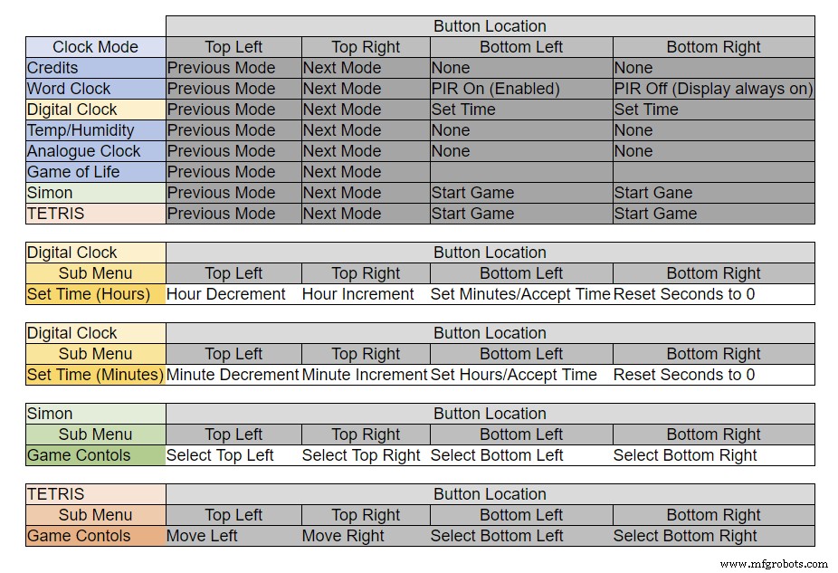
Los botones tienen diferentes funciones dependiendo del modo en que se encuentre el reloj, consulte la tabla anterior.
Paso 5:Configuración automática de verano e invierno
No utilizado.
Paso 6:Modos de visualización de relojes y entorno
La animación 1 anterior muestra los 4 modos de reloj y entorno.
Los modos están en orden reloj de palabras, reloj digital, temperatura y humedad y reloj analógico.
Animación 2 arriba. También hay un modo de inicio que se desplaza por el número de versión del software, el nombre del fabricante y el nombre del reloj.
Paso 7:Modos de visualización de juegos
Tres juegos clásicos están codificados en el reloj. He dejado el código como está del Reloj Catalán.

Animación 1 sobre el Juego de la vida de Conway. El universo del Juego de la vida es una cuadrícula ortogonal bidimensional infinita de celdas cuadradas, cada una de las cuales se encuentra en uno de dos estados posibles, vivo o muerto, o "poblado" o "despoblado".
Cada celda interactúa con sus ocho vecinas, que son las celdas adyacentes horizontal, vertical o diagonalmente. En cada paso en el tiempo, ocurren las siguientes transiciones:Cualquier célula viva con menos de dos vecinos vivos muere, como causada por la subpoblación. Cualquier célula viva con dos o tres vecinos vivos vive para la próxima generación. Cualquier célula viva con más de tres vecinos vivos muere, como por superpoblación. Cualquier célula muerta con exactamente tres vecinos vivos se convierte en una célula viva, como por reproducción.
El patrón inicial constituye la semilla del sistema. La primera generación se crea aplicando las reglas anteriores simultáneamente a cada célula de la semilla, los nacimientos y muertes ocurren simultáneamente, y el momento discreto en el que esto sucede a veces se denomina tic (en otras palabras, cada generación es una función pura de la anterior. una). Las reglas continúan aplicándose repetidamente para crear nuevas generaciones.
Animación 2 arriba de Simon
Juego de memoria Simon:prueba y copia la secuencia generada por computadora. Cuando ingreses tu secuencia, toca dos veces la última entrada para finalizar tu turno.
Cuando falla, su puntuación se muestra en la pantalla.
Animación 3 sobre TetrisTetris es el videojuego soviético de rompecabezas de emparejar fichas lanzado en junio de 1984. Este juego todavía necesita algo de trabajo en los botones para controlar las fichas correctamente.
Paso 8:creación de prototipos
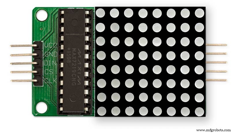
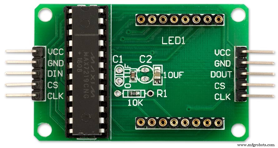
El reloj se puede crear un prototipo y probarlo utilizando los LED de matriz DOT originales en las placas de visualización MAX7219.
Tenga en cuenta que esta modificación temporal solo es necesaria si desea probar su código en las pantallas de matriz DOT suministradas con los módulos MAX7219.
Esto significa que puede probar su software / modificaciones de diseño de palabras en miniatura antes de comprometerse con la versión de tamaño completo. El cableado al LED DOT Matrix deberá modificarse para que coincida con las conexiones del software.
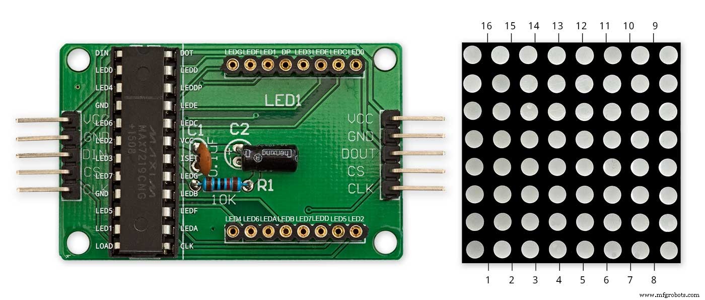
La imagen de arriba muestra cómo se conecta el módulo antes de la modificación. La modificación es bastante sencilla. En primer lugar, doble los siguientes pines LED Matrix 90 °, los pines superiores hacia arriba y los pines inferiores hacia abajo.
Pines 16, 15, 3, 4, 10 y 11.
Inserte la matriz de LED en el zócalo de la PCB de la pantalla, los pines anteriores ahora no estarán conectados. Suelde los siguientes cables de enlace desde la parte posterior del zócalo de la PCB de la pantalla a los pines LED Matrix que sobresalen.
LEDA al pin 16 de matriz de puntos
LEDB al pin 15 de matriz de puntos
LEDG al pin 3 de matriz de puntos
LEDF al pin 4 de matriz de puntos
LEDE al pin 10 de matriz de puntos
LEDC al pin 11 de matriz de puntos
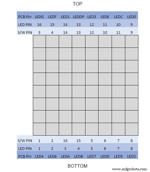
Usé un multímetro y activé el módulo de visualización. La tabla muestra dónde el número de pin del software difiere de los números de pin del LED en la placa de visualización.
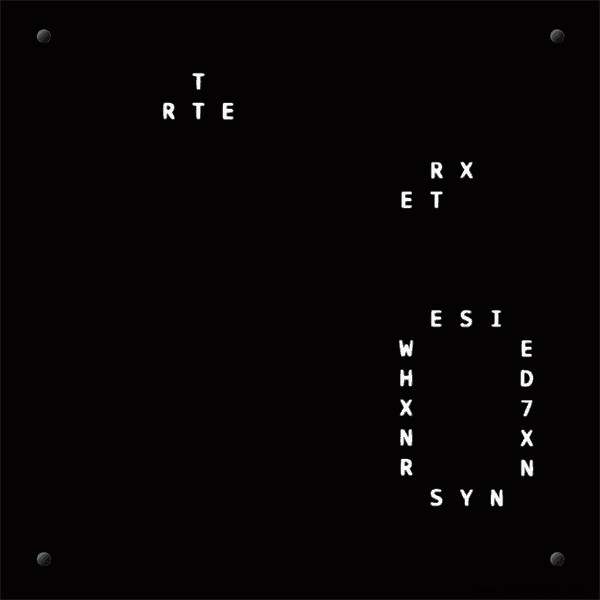
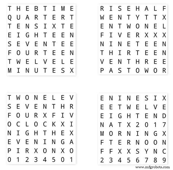
Para probar sus diseños de palabras, imprima una versión en miniatura de su pantalla de palabras de 62 mm x 62 mm en papel blanco normal.
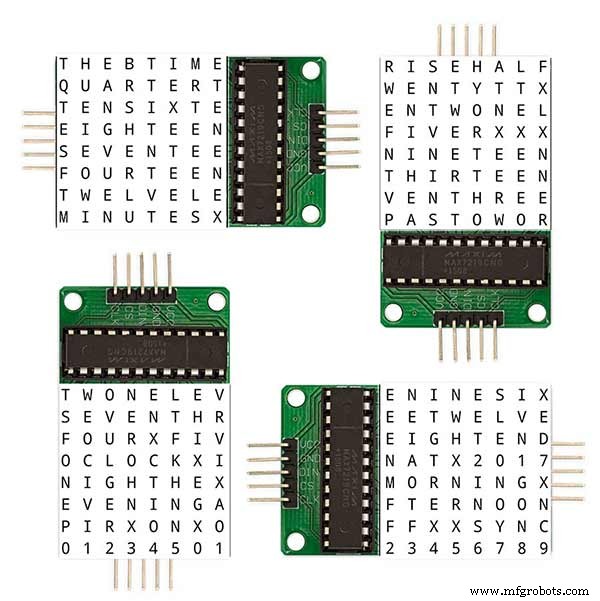
Tenga en cuenta la orientación de las placas de la pantalla LED para que coincida con el diseño del software.
He mantenido la rotación de la pantalla como el reloj original de Wouter Devinck en caso de que alguien use el diseño de PCB de Wouter Devinck para mi reloj.
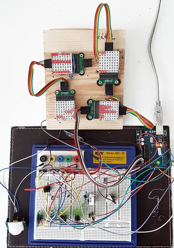
El pequeño botón pulsador debajo del sensor de temperatura / humedad se usa para probar la sincronización de 30 segundos. Los módulos de botones táctiles están en la parte inferior izquierda de la placa de pruebas montados lateralmente. No hay muchos cables en este prototipo ya que la mayor parte del cableado está en las matrices de visualización. En el reloj final, este cableado se realizará a mano a los LED individuales.
Probé muchos diseños diferentes de word / clock en esta placa antes de intentar construir el reloj final.
Paso 9:prueba de los módulos modificados
He modificado el boceto del reloj de palabras para permitir que el módulo MAX2719 se pruebe después del modo de cableado.
Todo este programa enciende cada LED por turno desde la parte superior izquierda a la parte inferior derecha de la matriz.
Simplemente conecte 5 cables al módulo NANO y MAX2719 y encienda el NANO desde su puerto USB. Cargue el boceto y déjelo correr.
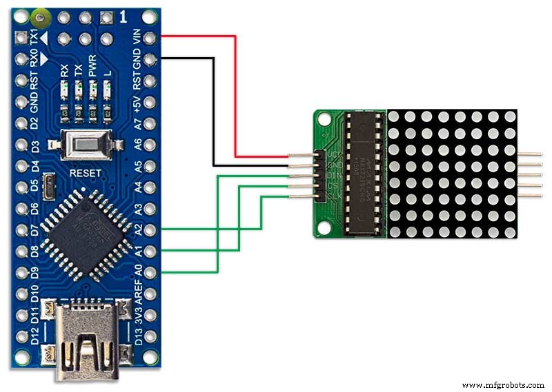
Simplemente conecte cada módulo a su vez para verificar su cableado.
Descargue el boceto de prueba del archivo zip adjunto.
MAX7219_LED_Test.zip
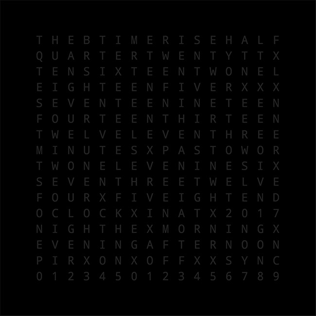
Paso 10:Tiempo para la asignación de palabras
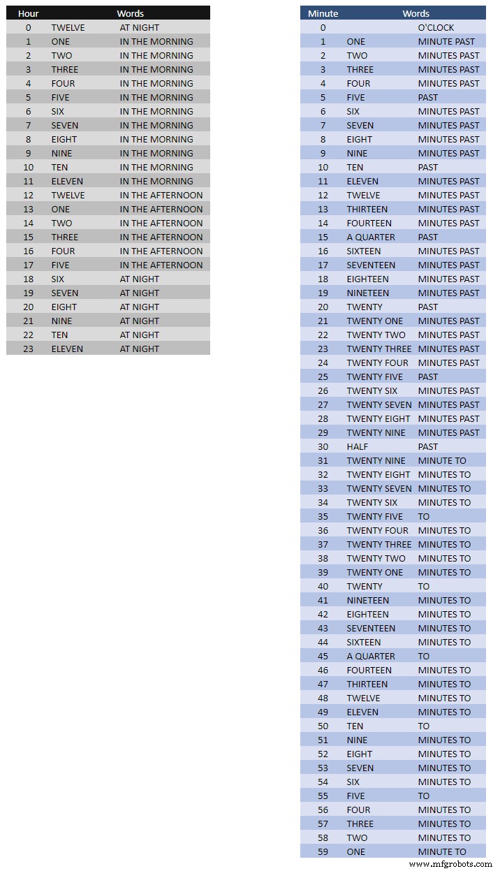
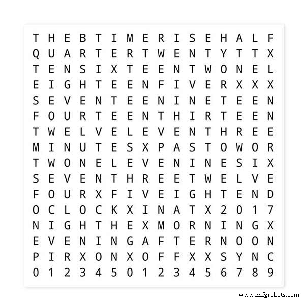
La tabla anterior muestra las asignaciones de tiempo para Word.
No hay reglas estrictas y rápidas sobre estos, simplemente establezca las palabras como diría la hora.
En mi reloj cambié lo siguiente en comparación con las palabras del reloj de Wouter.
"MINUTES" cambió a "MINUTE" en 1 minuto pasado y 1 minuto a la hora. Se agregó una "A" antes del "TRIMESTRE" pasado y "TRIMESTRE" a la hora.
Al mediodía cambió la hora para que diga DOCE EN LA TARDE.
A medianoche cambió la hora para que diga DOCE DE LA NOCHE.
Después de la medianoche, el reloj siempre dirá EN LA MAÑANA.
Estos cambios son muy fáciles de implementar en el software del reloj.
Palabra% 2B a% 2BTime% 2BTranslations.xlsx
Paso 11:Energía
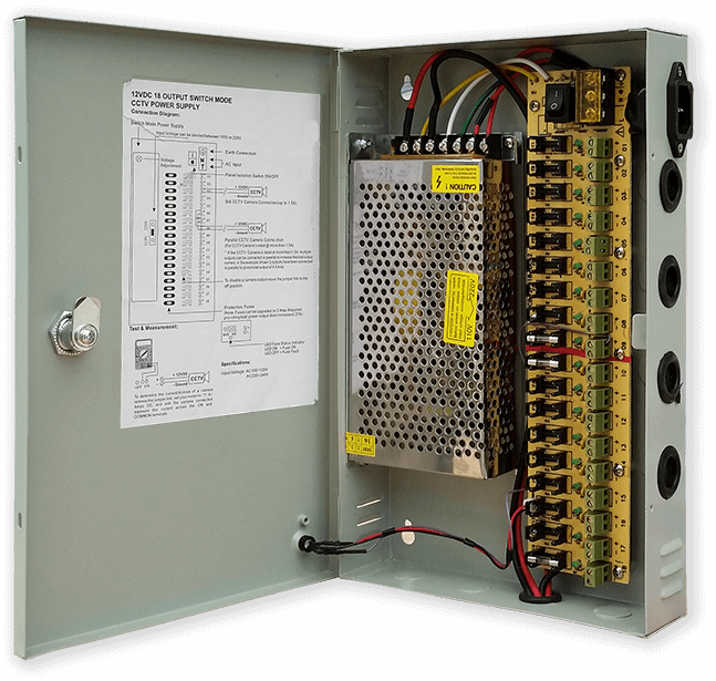
Utilizo una fuente de alimentación común de 12 voltios para impulsar muchos tipos diferentes de circuitos en toda mi casa. Este suministro de 12 voltios luego se reduce localmente en cada circuito con un módulo de 5 voltios para suministrar energía al tablero de control y varios módulos.
Mi fuente de alimentación común tiene 18 circuitos de 12 V con fusibles individuales, cada uno con un fusible de 2 A. 9 de estos tienen respaldo de batería. Los tableros de reloj también tienen su propio fusible a bordo.
Si está ejecutando solo este circuito, cualquier suministro regulado de 5 voltios funcionará siempre que pueda suministrar la corriente para el uso de su circuito.
He diseñado una placa de alimentación en Vero que utiliza una fuente de alimentación en miniatura MP1584. Esto convierte la salida de 12v de mi fuente de alimentación común a la de 5v para el reloj.
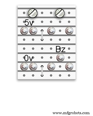
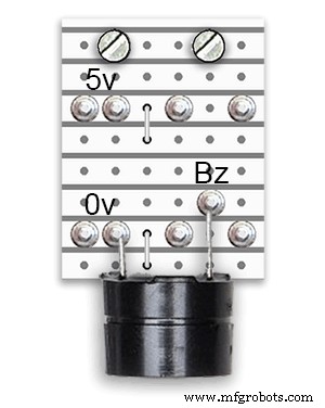
Hay dos placas de alimentación adicionales construidas a partir de la placa Vero.
Además de sostener el timbre, solo agregan puntos de distribución de energía adicionales para el cableado de energía del reloj.
Requisitos de energía
He medido el consumo de corriente del reloj y, con un brillo bajo, usa 30 mA y un brillo total de 250 mA. Por supuesto, esto variará con la cantidad de LED encendidos. En un día soleado, los niveles de brillo indicados en la salida serial son 10. Esto es alrededor de 2 tercios de la potencia máxima de los LED. El consumo total de energía se puede reducir considerablemente si el PIR está encendido. Esto dejará la pantalla en blanco si el reloj no detecta movimiento.
Usaría un suministro mínimo de 500 mA para alimentar el reloj. La energía dependerá en gran medida del tipo de LED que obtenga.
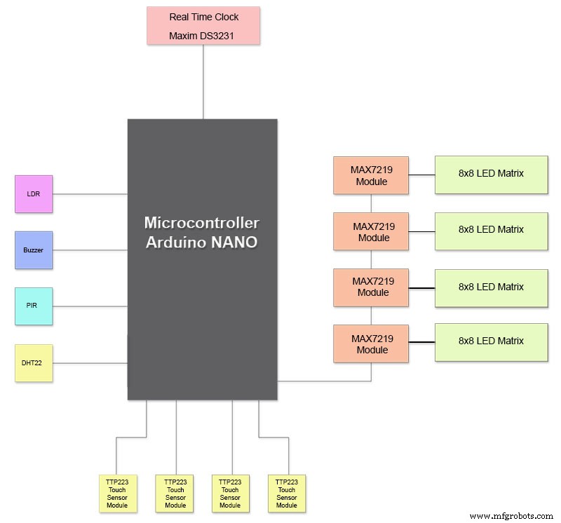
Paso 12:interconexiones de módulos
La imagen de arriba muestra cómo están conectados los módulos. La mayoría de los módulos se conectan directamente al Arduino Nano.
Las placas MAX7219 solo se conectan al NANO a través del módulo 01. Los otros módulos están conectados en cadena.
Luego, cada matriz de 8x8 LED se conecta a un módulo MAX7219.
La mayor parte del cableado son las conexiones entre los módulos MAX7219 y las matrices LED.
Mantenga la distancia entre el NANO y el primer módulo MAX7219 y el módulo MAX7219 a los módulos lo más corta posible. También asegúrese de suministrar energía a ambos extremos de los MAX7219 conectados en cadena, ya que esta parte del circuito consume la mayor parte de la energía.
Paso 13:Orden de construcción de la construcción
Orden de construcción suponiendo que todos los cambios de software y creación de prototipos se completen primero.
Obtenga una transferencia de vinilo impresa.
Haz un corte de vidrio.
Corte las hojas de MDF por delante y por detrás.
Haga agujeros en la hoja frontal para los LED.
Pinte hojas de MDF.
Corte agujeros para sensores en vidrio.
Pegue la transferencia de vinilo en la parte posterior del vidrio.
Corte los orificios del sensor en la placa frontal de MDF.
Corte los reembolsos del módulo del sensor en la placa frontal.
Corte el tablero trasero de MDF y haga 4 orificios de acceso para el acceso del sensor.
Agregue tiras de borde de melamina a los tableros de MDF, blanco al tablero delantero y negro al tablero trasero.
Atornille el tablero de MDF al tablero de MDF frontal.
Haga placas Vero, 1 placa de alimentación y 2 placas de distribución de alimentación.
Modifique 4 placas MAX7219 y agregue cableado a los LED.
Conéctese en el extremo MAX7219 solo por ahora.
Monte todos los módulos y placas Vero en la parte posterior de la placa frontal de MDF.
Construya las 4 matrices LED en la placa MDF frontal y suelde 256 LED.
Conecte todos los tendidos de batería y de tierra desde la placa Vero de la fuente de alimentación y las placas de distribución de energía.
Conecte todos los recorridos de alimentación a todos los módulos.
Conecte todo el cableado a los módulos Nano, MAX7219, RTC, sensor de temperatura, sensores táctiles y zumbador.
Conecte todos los mazos de cableado de las placas MAX7219 modificadas a las matrices LED según la tabla de cableado.
Conecte un módulo PIR de forma remota desde el reloj y conecte la conexión PIR.
Conecte la sincronización de 30 segundos a su reloj maestro (si es necesario).
Monte el panel de visualización frontal Glass utilizando los pernos Chicago que también fijan los sensores táctiles al mismo tiempo.
Prueba.
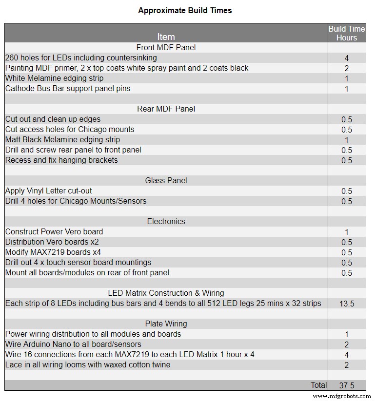
La Tabla 1 muestra los tiempos de construcción muy aproximados para este reloj y variará según su nivel de habilidad y también cualquier herramienta especializada / espacio de trabajo que tenga a mano.
Puede agregar fácilmente otras 40 horas de tiempo de programación y creación de prototipos a esa lista.
Paso 14:Adhesivo de vinilo de construcción
Adhesivo de vinilo
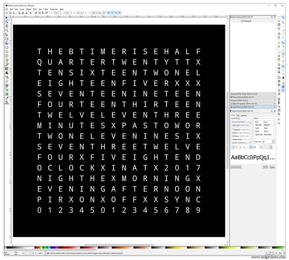
La pegatina de vinilo está diseñada en Inkscape.
Inkscape es un software de gráficos vectoriales de calidad profesional que se ejecuta en Windows, Mac OS X y GNU / Linux. Es utilizado por profesionales del diseño y aficionados en todo el mundo para crear una amplia variedad de gráficos, como ilustraciones, iconos, logotipos, diagramas, mapas y gráficos web.
Inkscape utiliza el estándar abierto SVG (Scalable Vector Graphics) del W3C como formato nativo, y es un software gratuito y de código abierto.
Descargué el diseño original de Inkscape de Wouter Devinck de su repositorio de GitHub y luego lo modifiqué en Inkscape para adaptarlo a mi diseño. Probé muchas versiones diferentes de mi prototipo en miniatura antes de enviar el diseño final a imprimir.
¡No olvide imprimir la pegatina al revés!
Usé una empresa llamada Regal Signs &Graphics que me suministró mi pegatina en vinilo negro, corte inverso, letras eliminadas y se suministró con una cinta de aplicación, todo por alrededor de £ 27 con iva.
Aunque son bastante locales para mí, pagué un poco más y me entregaron mi calcomanía en un bonito tubo de cartón seguro.
Tuve algunos problemas para obtener el diseño en el formato correcto para su máquina, pero al final lo envié desde Illustrator en formato eps, la gente muy servicial de Regal Signs lo redujo al tamaño correcto para mí. aquí PEGATINA DE VINILO.
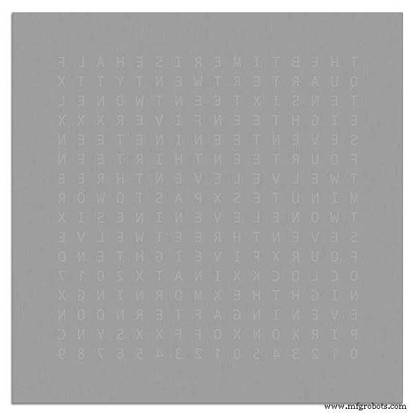
La calcomanía de vinilo vino de Regal Signs con las letras eliminadas, por lo que me ahorró mucho tiempo. La calcomanía viene con una cinta plástica en el lado frontal (vidrio) y un papel de aplicación en la parte posterior. Por lo general, se quita la cinta adhesiva lateral, se aplica la pegatina y luego se retira el papel de aplicación. Decidí dejar el papel de aplicación puesto que actuaba como difusor de los LED. Mientras dejaba el papel de solicitud, recorté el exceso de papel alrededor de la etiqueta antes de aplicar.
La aplicación de la etiqueta fue relativamente fácil. Solo asegúrese de ver algunos videos de YouTube en la aplicación de calcomanías de vinilo en el vidrio antes de probarlo usted mismo.
Vidrio

El reloj utiliza vidrio flotado de 4 mm y se ha cortado exactamente a 500 mm x 500 mm. Como los bordes están expuestos, los bordes también se han pulido. Todo esto lo hicieron mis vidrieros locales por £ 20.
Luego se perforaron orificios de 5 mm en el panel de vidrio usando un taladro para vidrio de 5 mm. Vea videos de YouTube sobre cómo perforar agujeros en vidrio.
Primero limpié el vidrio con acetona y me aseguré de que no tuviera polvo (muy importante). Luego me puse unos guantes de plástico para asegurarme de no dejar huellas dactilares en la pegatina.
Rocié el vaso con una mezcla de agua y jabón muy diluido y luego muy lentamente quité la película plástica de la pegatina para revelar la superficie frontal.
Es importante retirar la película lentamente y en un ángulo muy agudo para que las letras de la pegatina permanezcan unidas al papel de transferencia. Una vez que la pegatina esté completamente expuesta, aplícala sobre la superficie de vidrio húmeda.
La mezcla de agua y jabón te permitirá mover la pegatina al lugar correcto en el vidrio. A continuación, utilice una tarjeta de crédito y trabaje alejándose del centro de la pegatina para eliminar las burbujas de aire. Deje que la pegatina se seque durante la noche y luego, desde la parte posterior de la pegatina, corte el vinilo sobre los 4 orificios de montaje en el vidrio.
Brett11_print_ready.svg
Paso 15:Construcción de las placas principales, parte 1
Placas principales
La placa principal del reloj está formada por 2 láminas de MDF de 14 mm. La hoja trasera es 10 mm más pequeña que la hoja superior en todos los lados excepto en la parte superior. La parte superior tiene bordes blancos mientras que la parte trasera tiene bordes negros. Cuando se ve en la pared, el reloj parecerá tener 14 mm de profundidad.
La placa principal del reloj está formada por 2 láminas de MDF de 14 mm. La hoja trasera es 10 mm más pequeña que la hoja superior en todos los lados excepto en la parte superior. La parte superior tiene bordes blancos mientras que la parte trasera tiene bordes negros. Cuando se ve en la pared, el reloj parecerá tener 14 mm de profundidad.
En el reloj Wouter Devinck original y la versión "catalana" de Pijuana, se utiliza una única hoja de MDF de 18 mm de grosor con la parte posterior hacia fuera para dejar espacio para la placa de circuito impreso y los componentes. El uso de 2 hojas de MDF significa que el tablero se puede cortar simplemente con una sierra de calar en lugar de hacerlo con mucho tiempo y polvo. La hoja superior es de 503 mm x 503 mm para dar una superposición de 1,5 mm alrededor del vidrio. Esto le dará al vidrio un poco de protección contra golpes.
El tablero se corta con una sierra de calar y deja 14 mm de espacio para los componentes.
La PCB más profunda, incluidos los componentes, son los módulos MAX 7219 que tienen 10 mm de profundidad. Al finalizar, la placa trasera se pega o se atornilla a la placa frontal.
Construcción de tablero frontal
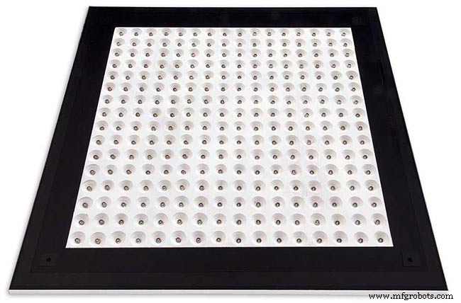
La placa frontal tiene 256 LED que brillan a través de orificios de 6,5 mm y orificios avellanados de 18 mm más anchos para iluminar letras y números individuales en la pantalla.
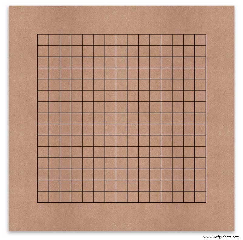
El tablero está marcado para mostrar la posición de perforación en el centro de cada carácter de la pantalla. Usando una pantalla de 500 mm, medí mi hoja de vinilo y los caracteres están separados por 25 mm, comenzando a 62,5 mm desde los bordes. Dibujé estas líneas en el MDF, las intersecciones son los puntos de perforación.
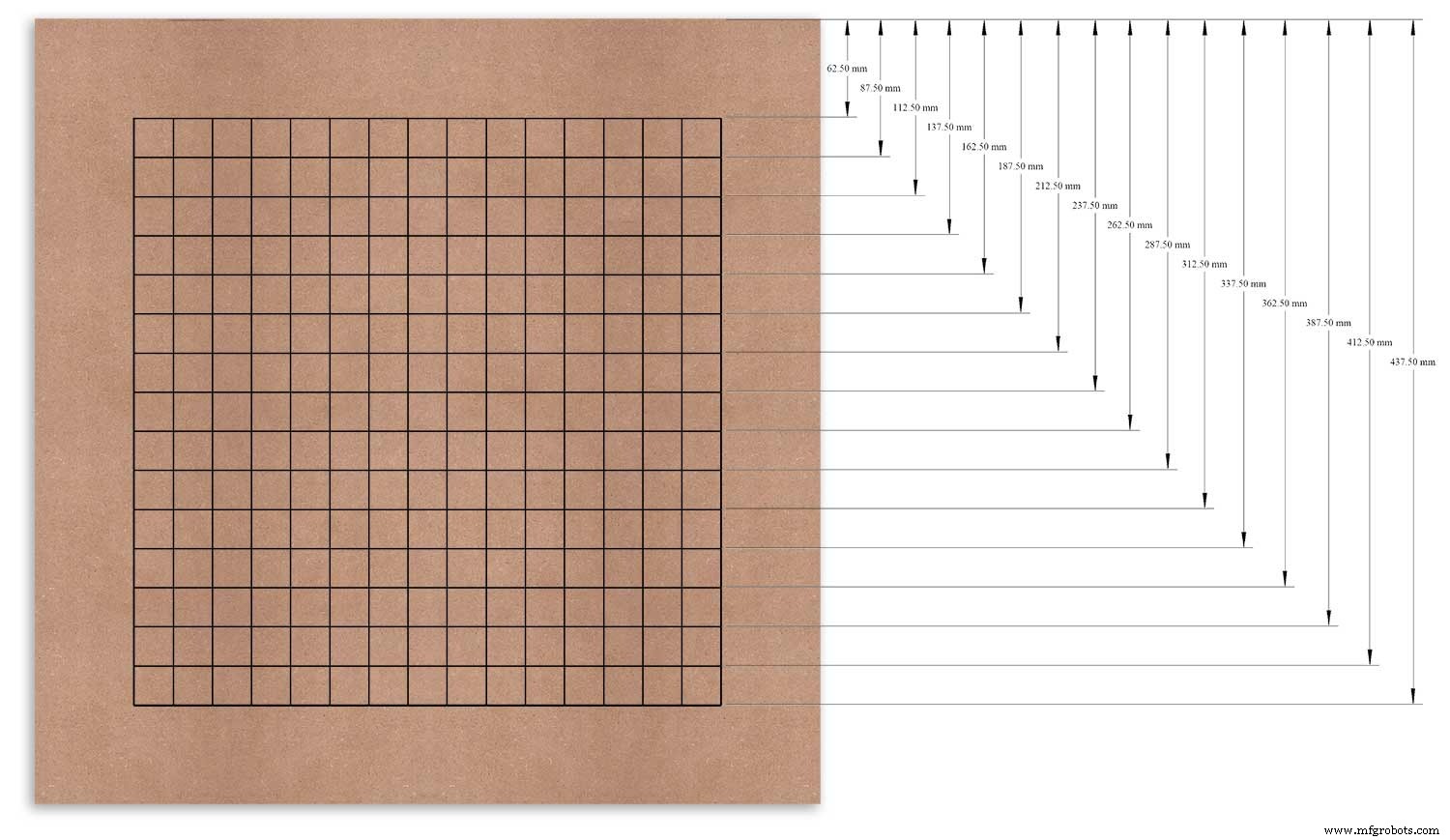
Usé el borde superior como punto de referencia que medí y marqué cada fila desde este punto.
Esto se repitió para la columna vertical usando el borde izquierdo como referencia.
Las intersecciones de la cuadrícula serán el punto central para los orificios de montaje del LED de 6 mm y los orificios avellanados de 18 mm.
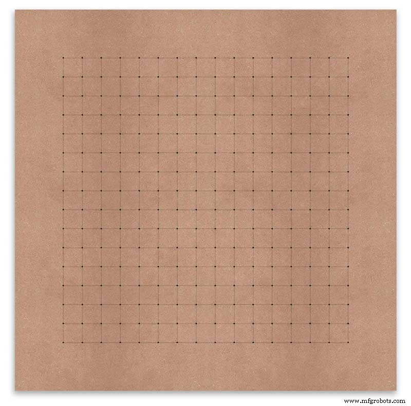
Using an automatic centre punch ( use a nail or screw if you don't have one) I punched the 256 intersection points of the grid.
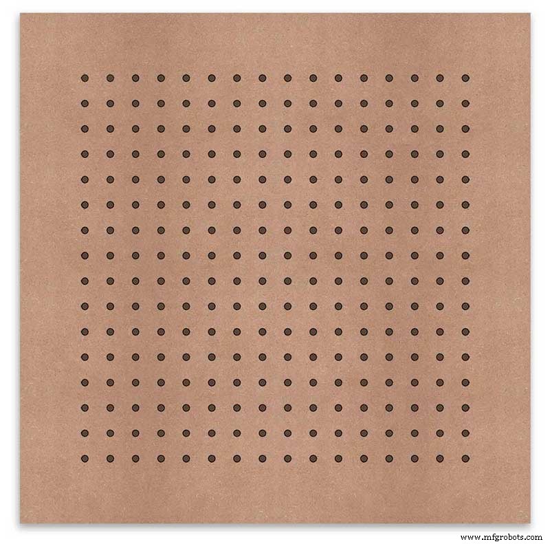
Using a drill bit to suite your LEDs (6mm in my case) and using the punched holes as a guide for the drill bit drill out all 256 LED mounting holes.
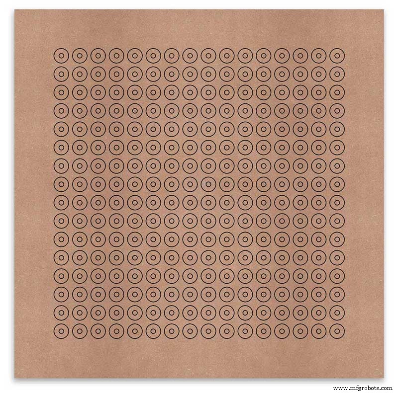
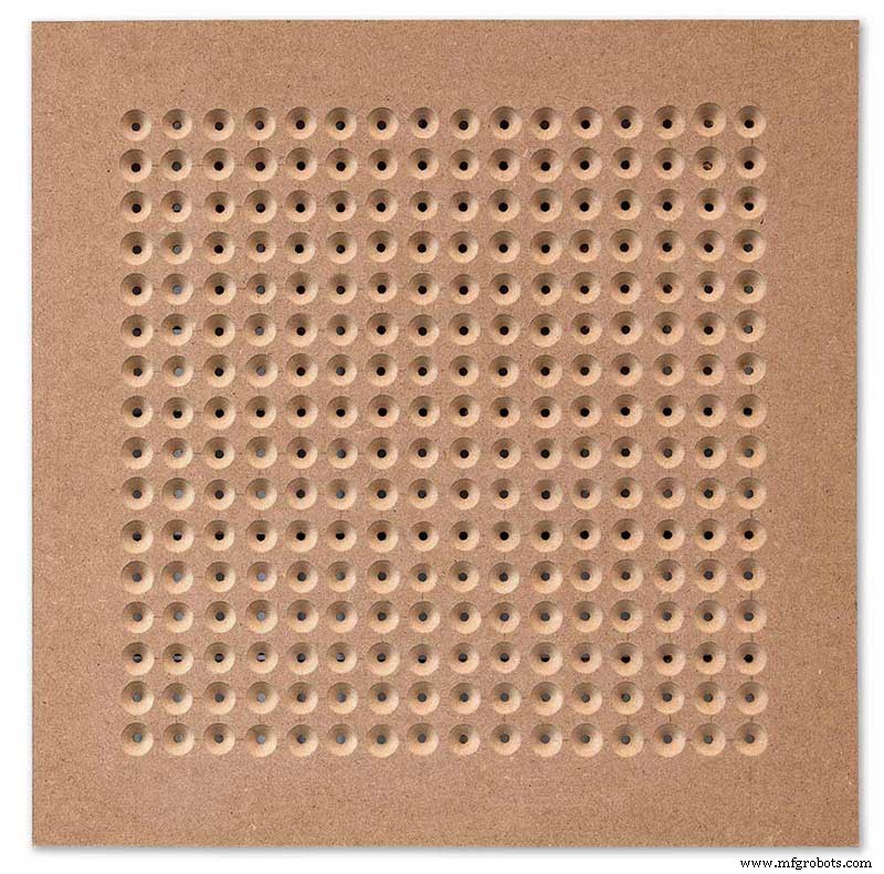
The next task is to drill the 256 18mm countersunk holes using a 20mm countersinking bit.
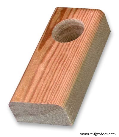
To keep the countersunk holes at a uniform depth and width I built a countersinking jig using an off cut of wood. To make the jig a hole is drilled in the wood off cut to just fit the silver rotating bezel of my drill chuck. Using a test piece of MDF the countersinking bit is then moved in and out of the chuck until a countersunk hole of the correct diameter is made when drilling through the hole upto the chuck in the off cut of wood. Once the correct distance is found the chuck is tightened and the main board is drilled 256 times by centring the hole in the wood over the existing 6mm holes then drilling down until the chuck bezel hits the hole in the countersinking jig.
Completed front board with 256 countersunk holes and 6mm holes for the LEDs.
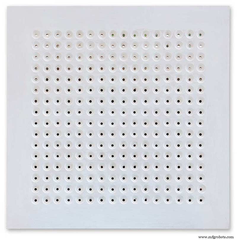
The board is then rubbed down and primed using MDF primer and painted white so the countersunk holes reflect the light from the LEDs.
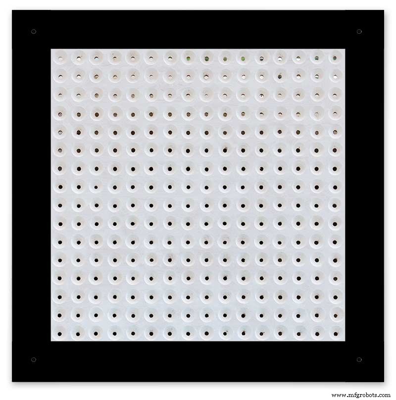
A black edge is painted around the outside edge to hide the board as the glass is 1mm shorter all round. This setback also helps the glass disappear from view on the final clock.
Four 5mm holes are then drilled in the corners to take the Chicago Fasteners. The Chicago Fasteners hold the glass in place, hold the touch sensors and provide a touch sensitive pad on top of the glass. The fasteners have 3mm shafts and will have a small bit of rubber tape wrapped around the shafts to protect the glass.
Turn the board over and drill a rebate with a forstner bit to take the four touch sensors. This hole will be offset from the hole drilled in the previous step.
Wall Mounts
The clock is fixed to the wall by two metal picture hanging mounts.
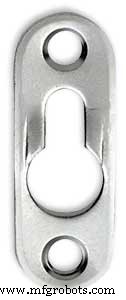
These are recessed into the frame so the highest point of the bracket is level with the frame.
Two 2" countersunk No6 screws sit in these bracket and hold the clock to the wall with a bit of tension so the dust seal is compressed.
Step 16:Construction Touch Sensor Mounting
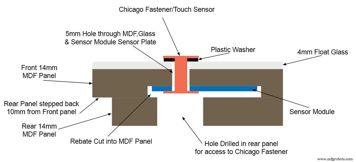
The touch sensor modules are fixed to the front panel using the Chicago Fastener bolts. The Chicago Fastener bolts then act as touch sensors.
A 5mm hole is drilled through the sensor pad on the module to allow the Chicago Fastener bolt to pass through.
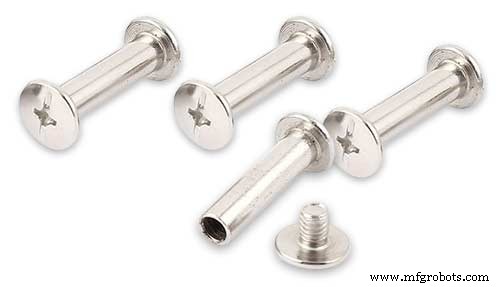
The sensor pad is insulated by the MDF panel and a plastic washer.
The touch pad on the sensor module has a 5mm mounting hole drill through the sensor.

Touch sensors in rebates behind rear panel. Holes drilled into rear panel allows access to the Chicago Fasteners that hold the sensors/glass front in place.
Clock front panel with four Chicago Fastener tops acting as touch plates.
Step 17:Electronic Components &Modules
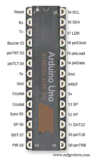
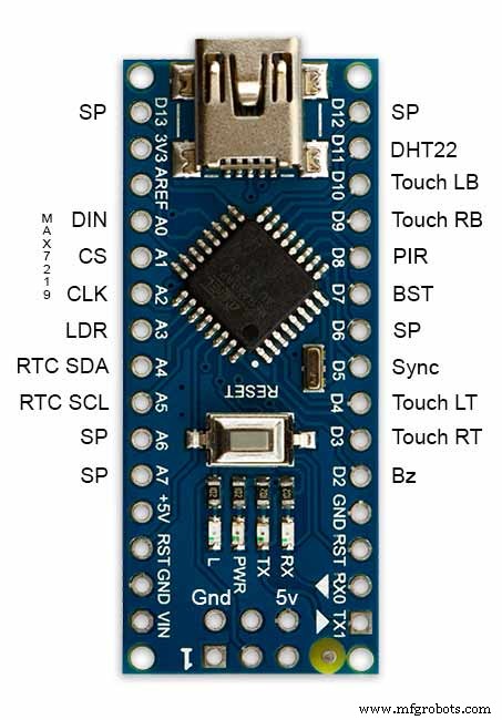
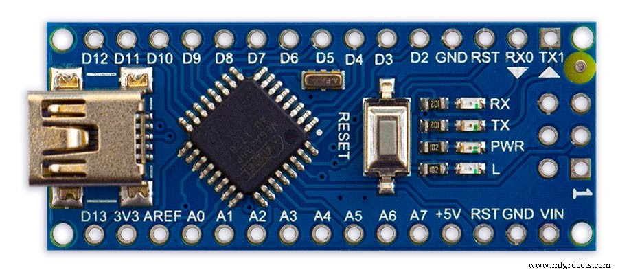
ATmega328 pin connections in case you want to prototype the circuit on an Arduino Uno. Note BST pin 07 is not used.
Pin label numbers refer to Arduino IDE numbers.
LEDs
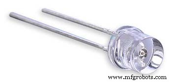
Make sure you purchase your LEDs from a good source. These LEDs will be on for many hours a day. I have has problems with LEDs failing after a few weeks use.
My LEDs Specs
5mm White Flat Top LEDs offering a pure and consistent colour with a wide angle ultra bright light output.
Colour :White
Quantity :256
Lenses Type :Round Flat Top
Crystal ClearBrightness :13000mcdForward
Voltage :3.2v - 3.8v
Forward Current :20mA (typical), 30mA (Max)
Viewing Angle :120 degrees
DHT22 Temperature &Humidity Sensor
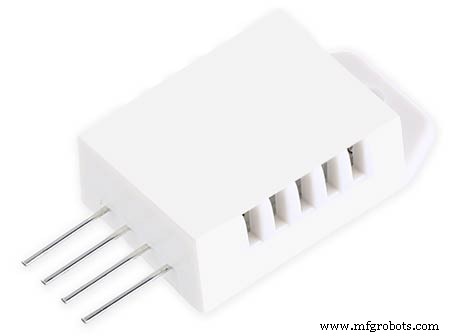
The DHT22 is a basic, low-cost digital temperature and humidity sensor. It uses a capacitive humidity sensor and a thermistor to measure the surrounding air, and sends out a digital signal on the data pin.
You can only get new data from it once every 2 seconds, so sensor readings can be up to 2 seconds old.
Simply connect the first pin on the left to 3-5V power, the second pin to your data input pin and the right most pin to ground.
To prevent the temperature of the inside clock case being measured the top and left side vent of the DH22 are covered over with tape. This also stops dust being drawn into the clock case.
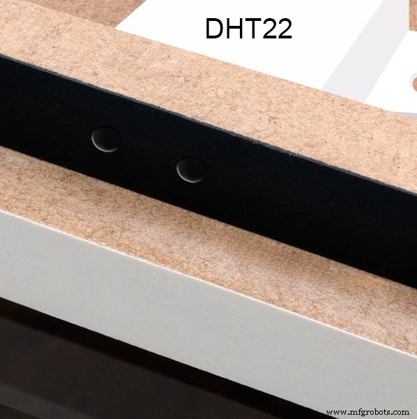
The DHT22 is mounted with its right open side mounted tight against the lower rear cover.Two small holes are drilled in the lower edge of the rear MDF board to allow air from the room to circulate around the sensor.
Arduino NANO
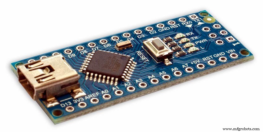
PowerThe Arduino Nano can be powered via the Mini-B USB connection, 6-20V unregulated external power supply (pin 30), or 5V regulated external power supply (pin 27). The power source is automatically selected to the highest voltage source.
Memory
The ATmega328 has 32 KB, (also with 2 KB used for the bootloader.
The ATmega328 has 2 KB of SRAM and 1 KB of EEPROM.
Input and Output
Each of the 14 digital pins on the Nano can be used as an input or output, using pinMode(), digitalWrite(), and digitalRead() functions. They operate at 5 volts. Each pin can provide or receive a maximum of 40 mA and has an internal pull-up resistor (disconnected by default) of 20-50 kOhms. In addition, some pins have specialized functions:Serial:0 (RX) and 1 (TX). Used to receive (RX) and transmit (TX) TTL serial data. These pins are connected to the corresponding pins of the FTDI USB-to-TTL Serial chip.
External Interrupts:2 and 3.
These pins can be configured to trigger an interrupt on a low value, a rising or falling edge, or a change in value. See the attachInterrupt() function for details.
PWM:3, 5, 6, 9, 10, and 11. Provide 8-bit PWM output with the analogWrite() function.
SPI:10 (SS), 11 (MOSI), 12 (MISO), 13 (SCK). These pins support SPI communication, which, although provided by the underlying hardware, is not currently included in the Arduino language.
LED:13. There is a built-in LED connected to digital pin 13. When the pin is HIGH value, the LED is on, when the pin is LOW, it's off.
The Nano has 8 analog inputs, each of which provide 10 bits of resolution (i.e. 1024 different values). By default they measure from ground to 5 volts, though is it possible to change the upper end of their range using the analogReference() function. Analog pins 6 and 7 cannot be used as digital pins. Additionally, some pins have specialized functionality:I2C:4 (SDA) and 5 (SCL). Support I2C (TWI) communication using the Wire library (documentation on the Wiring website).
There are a couple of other pins on the board:AREF. Reference voltage for the analog inputs. Used with analogReference(). Reset. Bring this line LOW to reset the microcontroller. Typically used to add a reset button to shields which block the one on the board.
Communication The Arduino Nano has a number of facilities for communicating with a computer, another Arduino, or other microcontrollers. The ATmega328 provide UART TTL (5V) serial communication, which is available on digital pins 0 (RX) and 1 (TX). An FTDI FT232RL on the board channels this serial communication over USB and the FTDI drivers (included with the Arduino software) provide a virtual com port to software on the computer. The Arduino software includes a serial monitor which allows simple textual data to be sent to and from the Arduino board. The RX and TX LEDs on the board will flash when data is being transmitted via the FTDI chip and USB connection to the computer (but not for serial communication on pins 0 and 1). A SoftwareSerial library allows for serial communication on any of the Nano's digital pins. The ATmega328 also support I2C (TWI) and SPI communication. The Arduino software includes a Wire library to simplify use of the I2C bus. To use the SPI communication, please see ATmega328 datasheet.
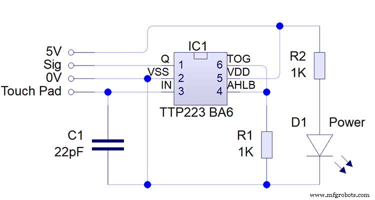
TTP223 Touch Sensor Module
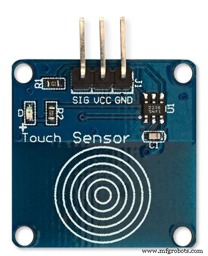
The touch Sensor Module is bolted to the front panel using the glass mounting bolts. The bolt goes through a 5mm hole drilled in the middle of the sensor.Note the mounting bolt is touched to trigger the sensor but is insulated from the sensor itself through plastic washers. Four of these modules are used in the clock one mounted on each corner of the glass.
Note the LEDs are not required and are removed from the modules (just break them off) to save power.
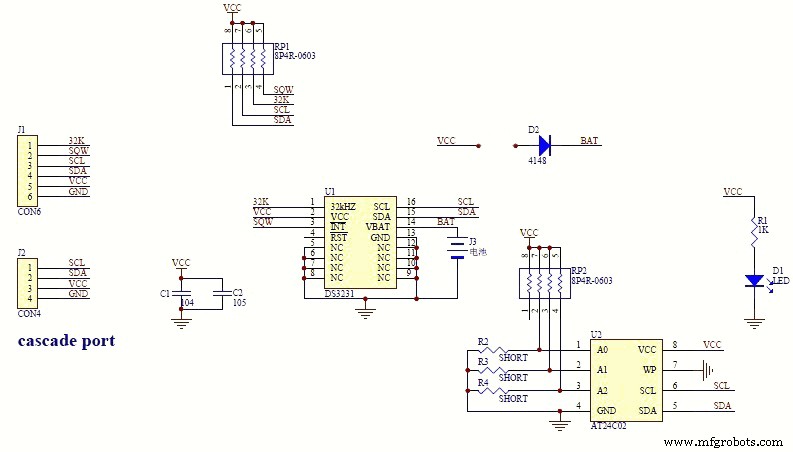
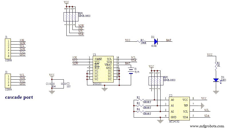
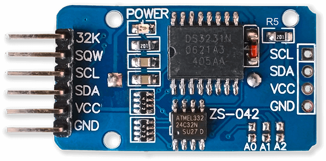
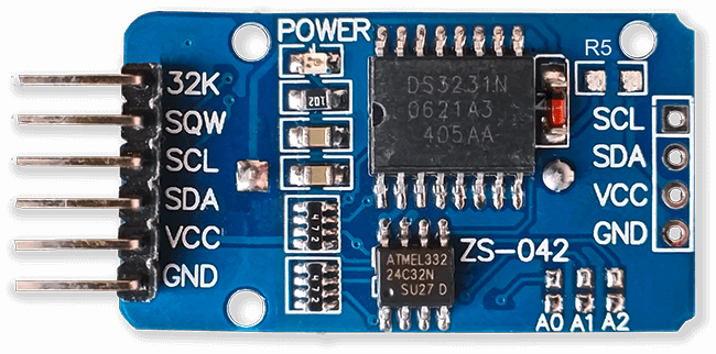
DS3231 AT24C32 I2C Precision Real Time Clock Module
My clock uses a DS3231 AT24C32 I2C Precision Real Time Clock Module.The module comes supplied with a Lithium-Ion rechargeable battery see diagram below. I use a non rechargeable battery so have removed resistor R5 from the module.
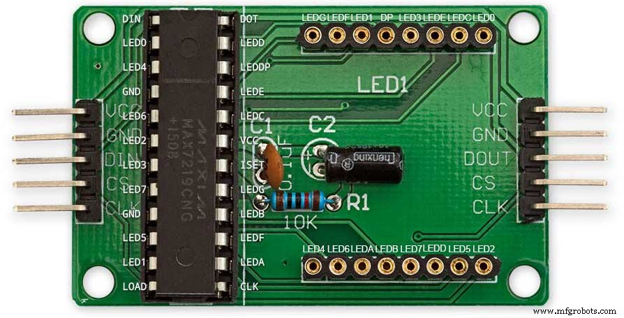
MAX7219 Display Module
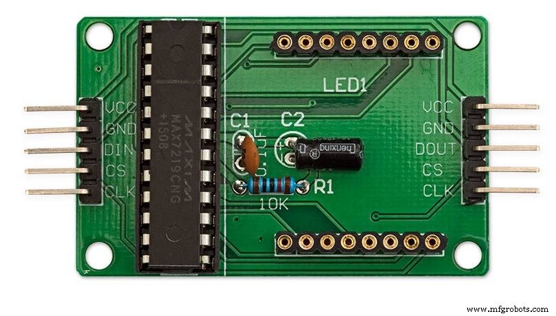
MAX7219 LED current limiting
The max current through the LEDs is set by a single resistor R1 on the module. The value of resistor can be found from the table below.
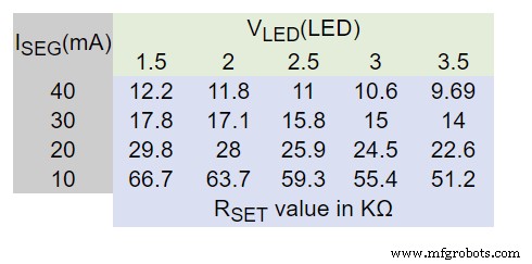
The module comes with a 10K resistor preinstalled but this can be removed and a resister to match your LEDs current added in its place. My LEDs Forward Voltage is 3.2v - 3.8v @ 20mA. They can handle 30mA max but for long LED life 20mA is best. I have used 22KΩ resistors which will limit the current to around 20mA when the light levels are at their peek.
See setting automatic brightness levels.
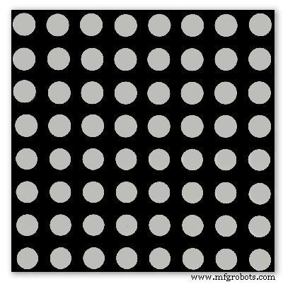
1088AS LED Dot Matrix display

1088AS LED Dot Matrix display view of lower edge Pins 1 to 8 left to right.
This is used for prototyping and is not required in the final project.
LDR
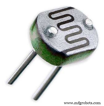
An LDR is used to sense the ambient light levels. The LDR is around 500Ω in bright light and 10MΩ in the dark.
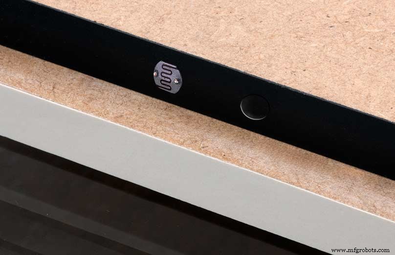
The LDR is positioned underneath the clock on the rear MDF panel.
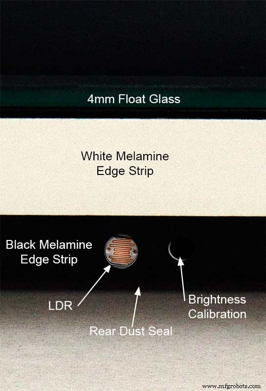
Next to the LDR is a hole to give access to the trimmer resister to calibrate the LED brightness control.
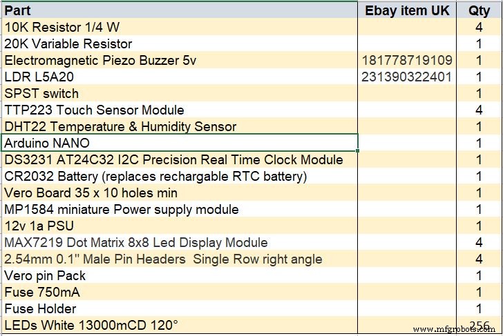
Component List
Step 18 Dust Seals
To prevent ingress of dust two dust seals are fitted.
On the rear MDF board a 2mm soft foam rubber dust seal is fitted. When the clock is hung on its hanging hooks the seal is under pressureand seals the back of the clock to the wall.
The seal is self adhesive and is fitted with a 5mm gap to the edge of the rear MDF board.
On top of the front board to prevent dust getting under the glass a strip of self amalgamating rubber is fitted 5mm from the board edge.
To prevent the glass from cracking when the Chicago bolts are tightened 4 small square of rubber are also fitted around the holes in the glass.
I punched holes for the Chicago Bolts in the rubber with a leather punch.
Step 19:Schematic
Nano Connections
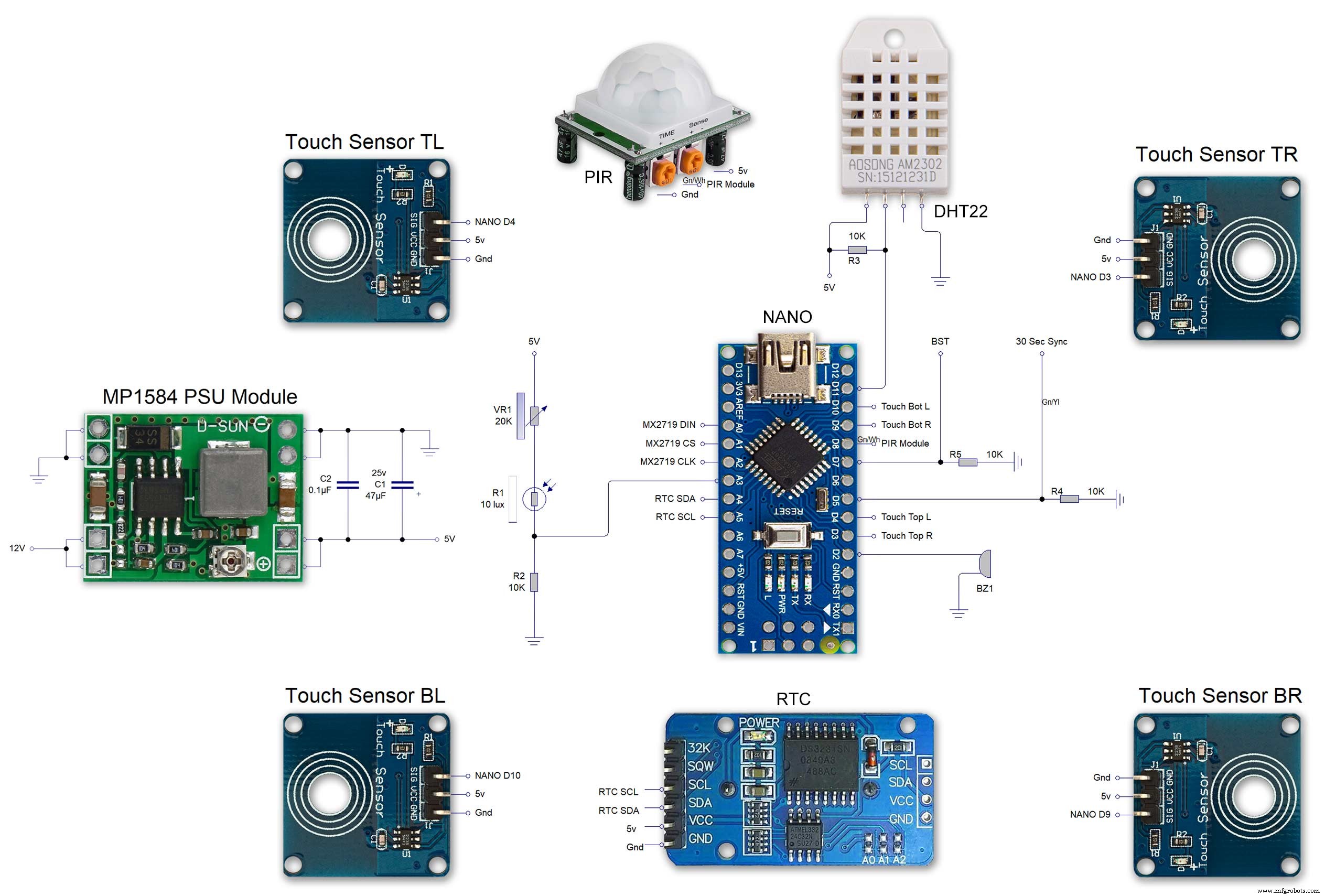
The connections to the Arduino Nano. Download the full size file from the hardware section
MAX2719 connections


The 4 MAX7219 modules and the connected LED matrixes.
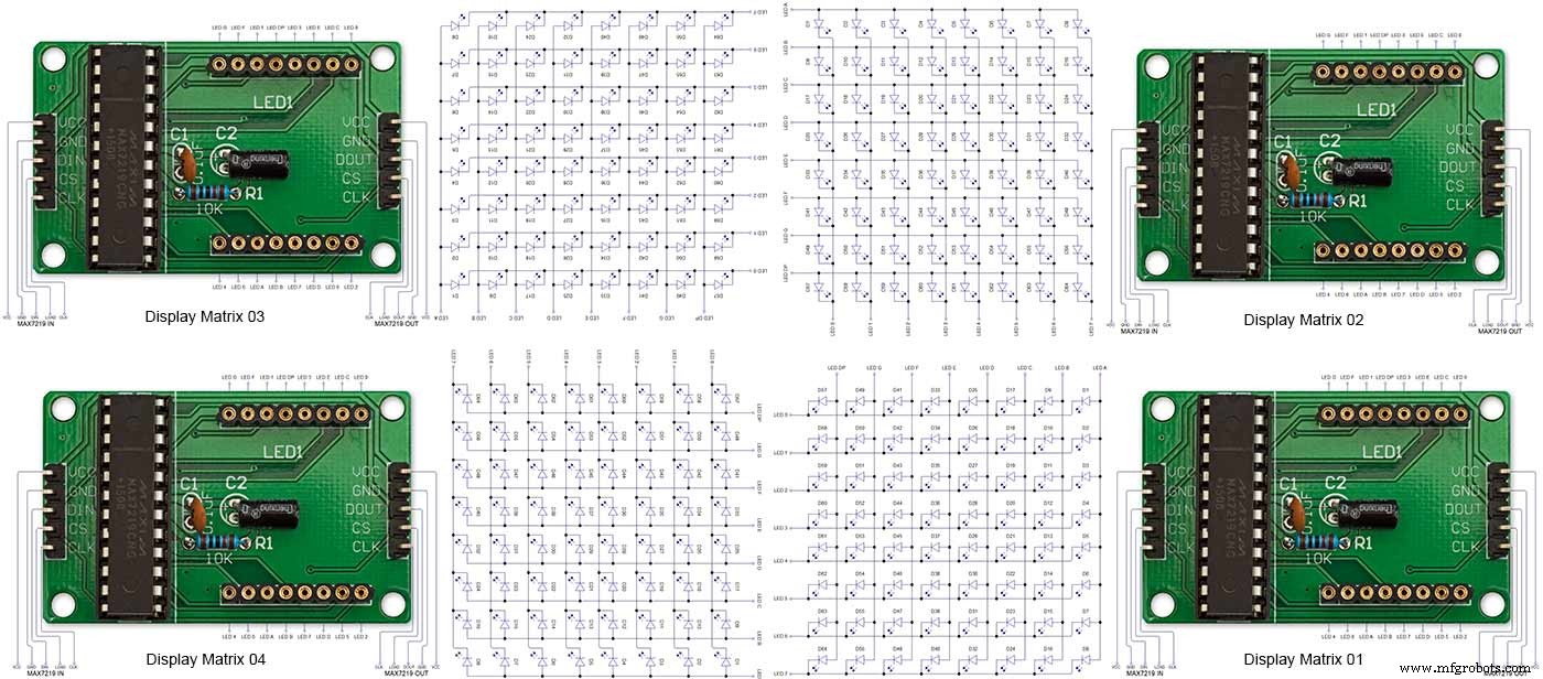
Note the LED display matrixes are rotated anti-clockwise 90 degrees from each other starting from display matrix 01.Display Matrix 01 input is wired to the Arduino CLK, DIN and LOAD the output is taken to the input of Display matrix 02 etc etc.
Step 20:Wiring Building the LED Matrixes
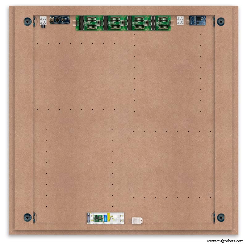
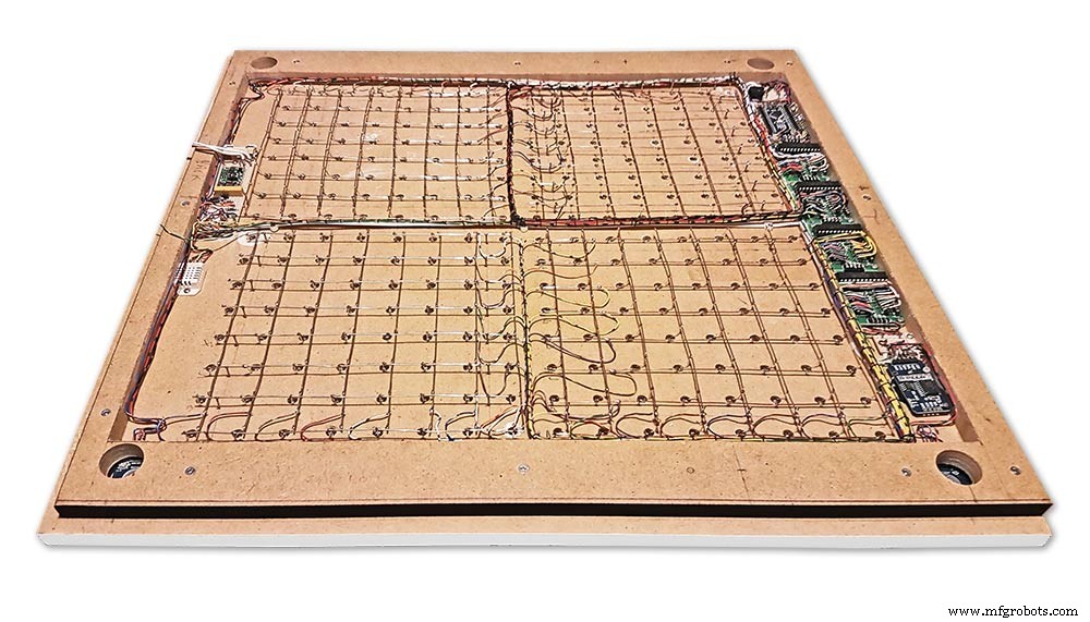
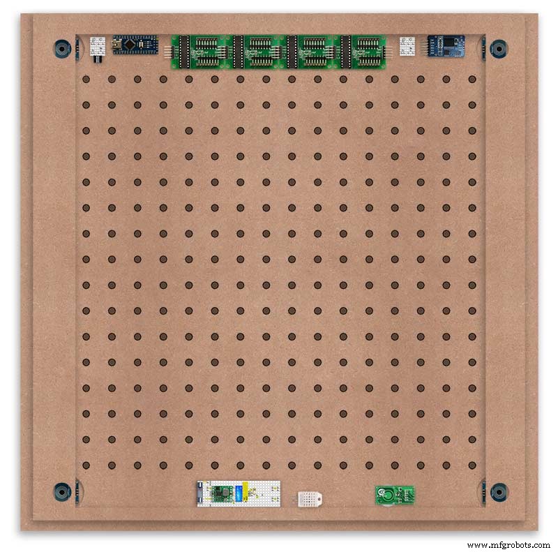
Module Locations

The module locations are shown above. The four sensors are located in the recesses on the main board behind the rear board. Holes are cut into the rear board to allow access for fit the Chicago Bolts/Sensor pads.
The four MAX7219 Display Modules are soldered together and are mounted in the centre top of the board. This keeps the data links between the boards as short as possible.
The Arduino Nano is mounted on the left of the MAX7219 Display Modules and the RTC on the right. The RTC battery holder on the base of the RTC module is recessed into the main board.
The Vero board containing the power module is located on the lower part of the board. There are two power distribution boards mounted on the top of the clock. The main 5v 2A feed cable is taken to both of these boards and power is then distributed to the other boards from these points.
The MAX7219 board power is fed from the left board and daisy chained through each board then taken out the forth board to ensure they are fed with 0v and 5v from both ends.
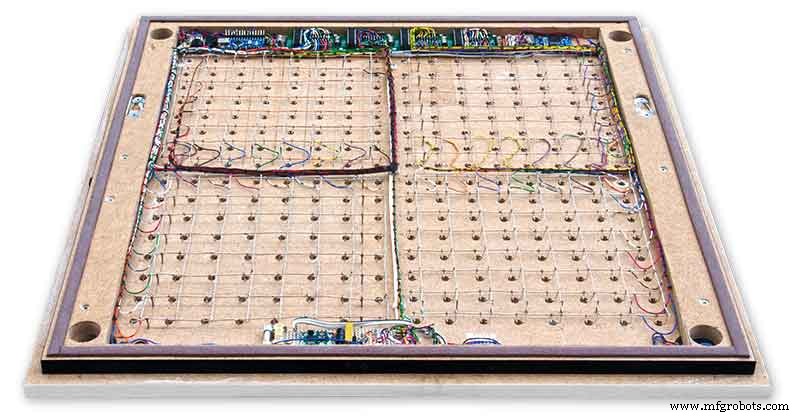
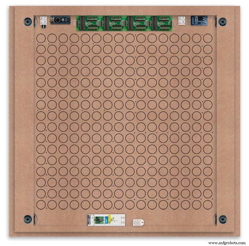
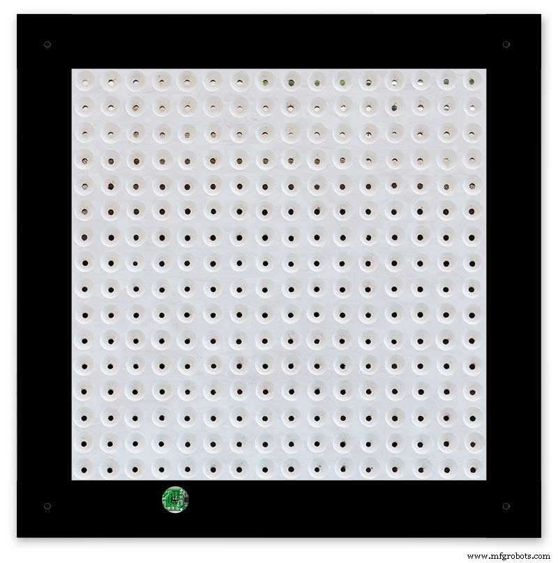
The LED locations are shown. The LED matrixes each contain 64 LEDs and are labelled 1 to 4.
These correspond to the 4 MAX 7219 modules mounted above numbered 1 to 4 left to right. Note this is the rear of the clock so number will be revearsed.
The LED Matrixes are built up off 2 types of BUS Bars per module. A Cathode Bus at 10mm high and an Anode BUS bar at 2mm high.
There are 8 Cathode and 8 Anode BUS Bars per module. Each module has 16 x 15mm panel pins hammered into the board in the position shown to support the 10mm high Cathode BUS.
The 15mm panel pins are hammered in 5mm (I used a 10mm piece of metal bar as a gauge) leaving 10mm as Cathode BUS bar support pins.
As shown above the pins correspond with the thick parts of the board not the recess for the LEDs on the front of the board. Note the LED recess is on the front of the board and can't be seen from the back.

0.9mm copper wire is then soldered to each pair of pins to form the Cathode BUS Bar.
Note the rotation of each module and also the modules are in reverse as it is the back of the board the LEDs are connected to.
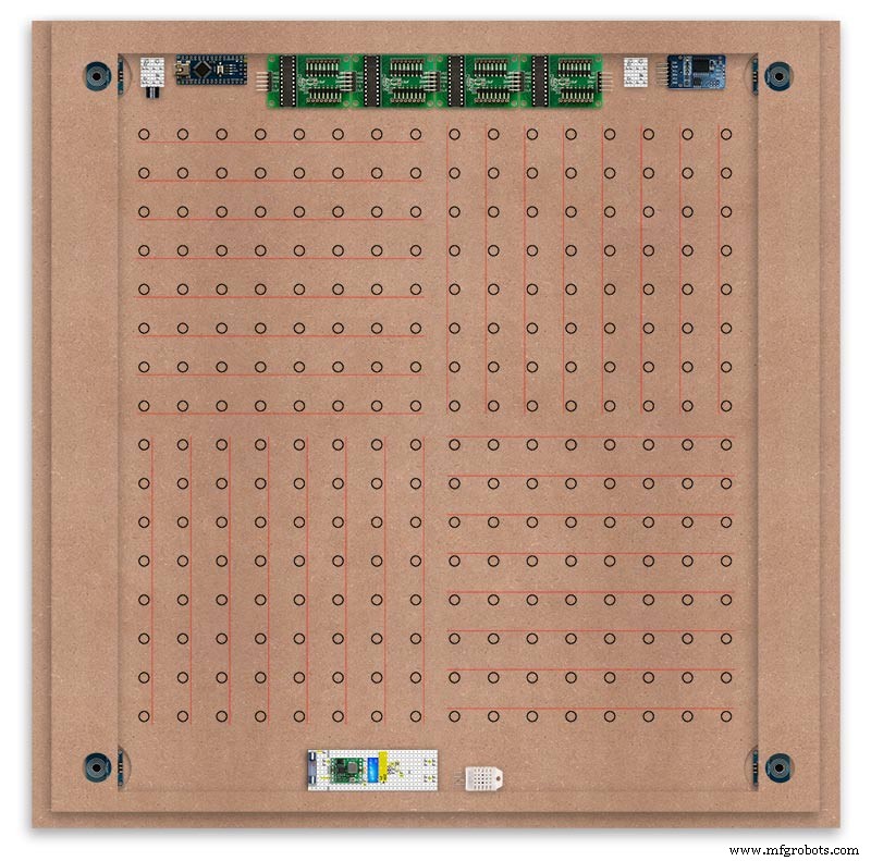
The Anode BUS Bars are shown below in Red and are supported off each LED Anode about 2mm off the MDF board. No Pins required.

Both Cathode &Anode BUS Bar locations are shown below.
Each LED is connected to an Anode and Cathode of the Matrix.
Step 21:Wiring the LEDs
LEDs
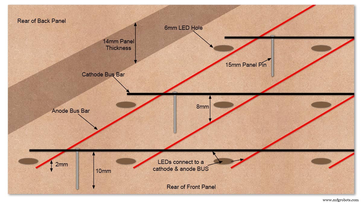
Diagram showing Bus Bar layout with panel pins supporting the Cathode Bus. This module has horizontal Cathode and vertical Anode Bus Bars.
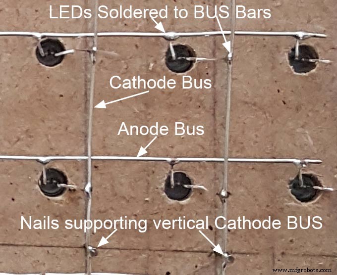
Close up section of Module wiring.The Cathode BUS Bars run vertically and the Anode BUS Bars run horizontally on this module. The Anode &Cathode BUS Bars have an 8mm vertical separation.
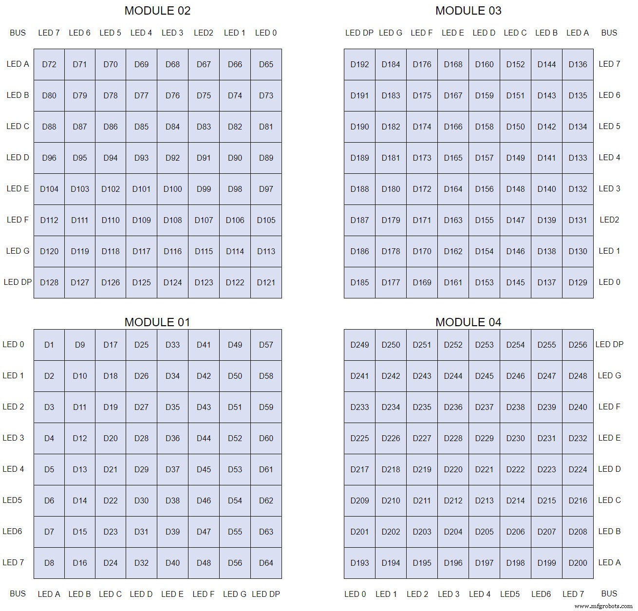
The LEDs are connected to the matrixes and MAX7219 modules from the rear. The LED positions will be reversed and of course rotated 90° relative to the next module. This makes it very complicated connecting the correct LEDs and Bus bars from the rear of the board. The table below shows the LED positions in the blue boxes with the BUS Bar matrix position in black around the outside as they appear from the back of the front MDF board.
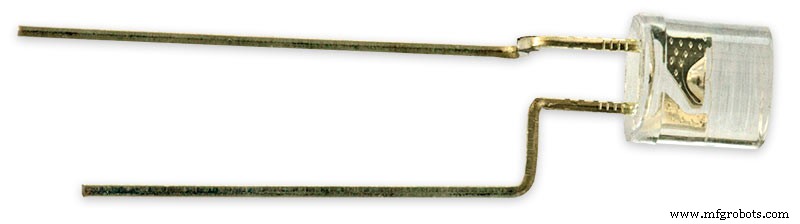
The LEDs are bent in a jig to keep the position in the display constant and to speed up construction. Each LED has four bends two on each leg that's 1024 in total! The Cathode leg is bent 90° from the Anode.
The Matrix grids are wired to the corresponding pins on the MAX7219 modules according to the layout table.
There are 16 wires to each module.
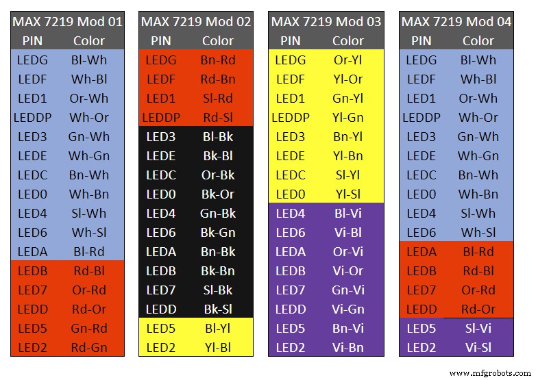
Table 1 Module LED Matrix Wiring Colour Code is shown above.
Each Module has 16 wires connecting it to the LED Matrixes. I have used 50pr 0.5mm cable so the last 14pr colours are duplicated. On Mod 4 I went out of order and missed out the Sl/Vi at the start so have put it in at the end.
Step 22:Wiring Modifying the MAX7219 Modules
Before wires can be connected to the MAX 2917 modules they will need to be modified.
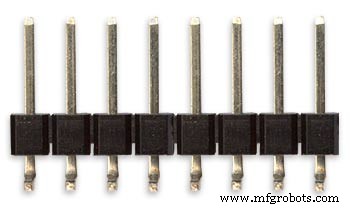
Two sets of 8 90° pin connectors will to be soldered to the lower edge of the existing LED matrix connector.

Modified MAX7219 module with 90° pin connectors soldered in place to the bottom of the old LED Matrix connectors.
Wires are taken away from these points to the LED matrix on the main MDF board as per the LED Matrix Wiring Colour Code table on the previous step.
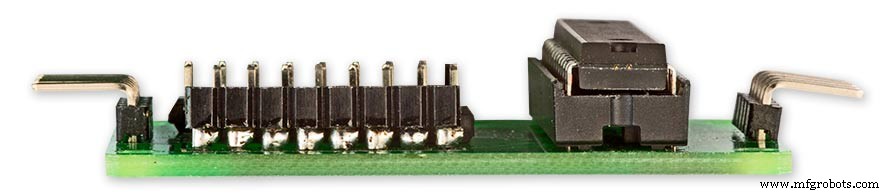
Side view showing the pins soldered to the side of the old LED Matrix connector pins just above the PCB.
Note if your MAX7219 Module does not have surface mount components the 90° pin connectors may need to be trimmed back so they don't foul R1, C1 or C2.
MAX7219 LED current limitingThe max current through the LEDs is set by a single resistor R1 on the module. The value of resistor can be found from the table below.

The module comes with a 10K resistor preinstalled but this can be removed and a resistor to match your LEDs current added in its place.
My LEDs Forward Voltage is 3.2v - 3.8v @ 20mA. They can handle 30mA max but for long LED life 20mA is best. I have used 22KΩ resistors which will limit the current to around 20mA when the light levels are at their peek.
Note this sets the max current through your LEDs actual brightness is controlled by the LDR/software/ trimmer resistor and will usually be far less than this.
Setting Automatic Brightness Levels
The clock automatically senses the ambient light and adjusts the LEDs accordingly.
When first installed the clock will need to be calibrated to the maximum light levels in its actual location.

Connect a mobile, laptop/tablet etc via a suitable cable to the mini USB port of the clock and open an app to monitor the serial port.
I use Slick USB 2 Serial Terminal on my S7 via an OTG cable and USB to mini USB cable.
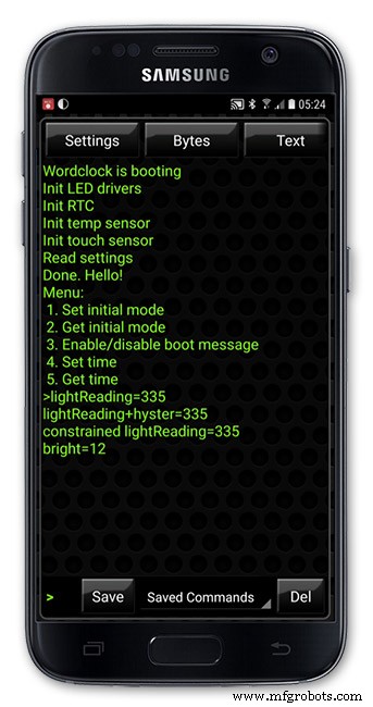
The clock will reboot and after the initial start screen you will see the following data updating down the screen.
You don't need to worry about lightReading or constrained lightReading+hyster just light reading, and bright.
With the clock in position and the ambient light at its maximum levels carefully insert a flat bladed jewellers screwdriver into the access hole just to the right of the light sensor.
Turn the screwdriver slowly until the light reading =600 (or your level set in brightness.cpp) and bright =15.
Your clock will now go to max brightness when the ambient light is at its maximum.
If you turn the screwdriver too far the light reading will go over 600 but the bright reading will not increase.
If you want the clock to be dimmer right across the range of ambient light levels adjust the light reading to a level less than 600 at max ambient light levels.
Note when bright=15 this will output the max current to the LEDs. The max current is set by R1( RSET) on the MAX7219 module and this should be chosen for your type of LED used in the display.
Step 23:Wring Mini USB Port
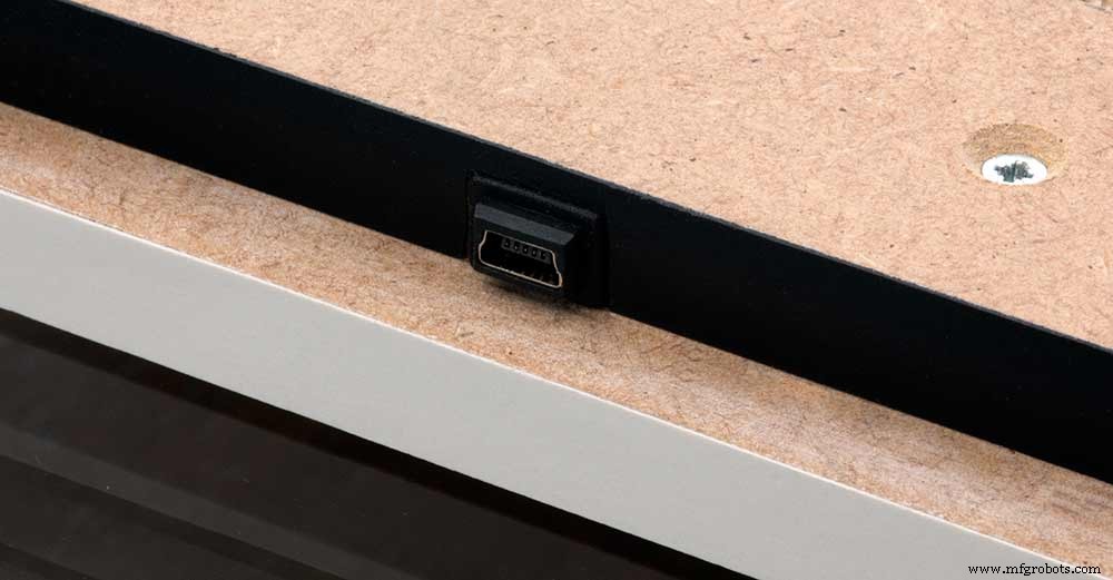
To allow adjustment/checking of light levels and programming of the clock a Mini USB socket is cut into the right hand side of the rear MDF sheet.
I have used a 25cm 90° Right angle Mini USB Male to Female Extension Cable and stripped back the insulation sleeve and shielding to expose the wires. This allows the cable to bend around the sharp angles and tight spaces of the enclosure.
Step 24:PIR Controlled Display Shutdown
This is optional as a Doppler Radar module can be fitted inside the clock instead.
See next section.
The PIR when enabled on the word clock menu (bott left PIR On, bott right PIR Off) turns on the display when movement is detected in the room.
When no movement is detected the display turns off after a set period of time. When the PIR is enabled the displays shows "PIR ON" and when disabled (display always on) it shows "PIR OFF" Note when the PIR is not enabled the display is always On.
The PIR module is fitted remote from the clock in a modified chrome light switch box. The box is cut into a plasterboard wall and also contains a switch to turn the clock off. The module itself is very small and can be mounted in a tiny enclosure if you don't want it on show. It will not work behind glass so if you wanted to mount it on the clock a hole would need to cut in the glass. This is very easy to do with a large hole cutter.
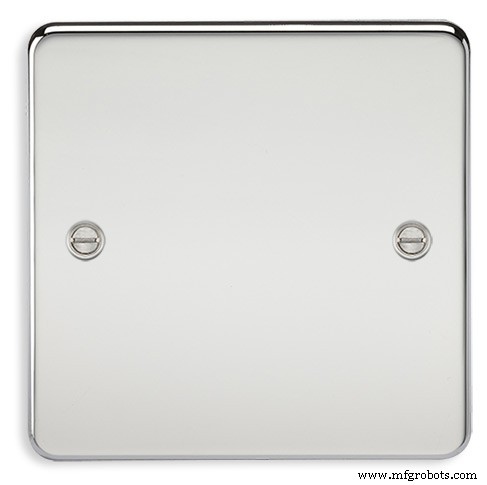
A blank chrome switch plate and back box are used to house the power switch and PIR module.
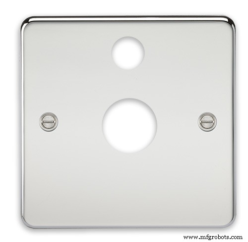
Two holes are drilled in the blank switch plate for the power switch and PIR lens.
The hole are centre punched, pilot drilled and then drilled out just big enough for a step cutter to fit through. The hole for the PIR diffuser is cut just big enough for the lens to go through with a friction fit.
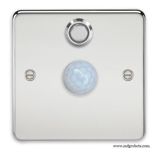
The completed switch plate.
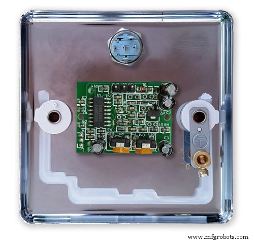
The 12 volt supply +ve is terminated on the switch with the 0v terminated on the earth screw.
12 volts is then fed back upto the clock PSU Vero board from the other side of the switch and again the earth screw. 5 volts are fed from the clock PSU Vero board to supply the PIR module.
The 5 volts and PIR sensor wire to the clock terminate on PCB header sockets. These are is plugged into the PIR Module header pins. The sync cable is terminated on a header pins and connects to the Master Clock 30 second sync cable via a single header socket.
The PIR has 2 trimmer resistors for adjusting sensitivity and also length of time the PIR &display stay activated.
PIR On/Off Control:The PIR is turned on and off in word clock mode by touching the bottom left sensor to turn the PIR on or by touching the right sensor to turn the PIR off. Note when the PIR is set to off the display stays on permanently. When you change the PIR setting the work "PIR ON" or "PIR OFF" is displayed for 5 seconds.
When initial power up the default is PIR off if you switch the PIR On straight away the display will go off as the PIR takes a minute or so to initialise before detecting movement.
Photo 6 &7 "PIR ON" or "PIR OFF" are displayed for 5 seconds when PIR setting is changed.
Step 25:Doppler Radar Control Option
Optional Doppler Radar Module can be added in place of the PIR above.
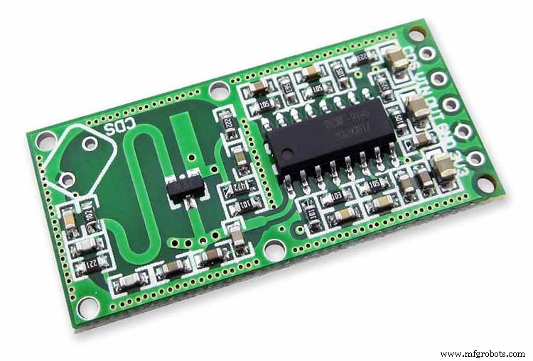
The Doppler Radar when enabled on the Word Clock menu (bott left PIR On, bott right PIR Off) turns on the display when movement is detected in the room. A check is made for motion on every quarter hour. When no movement is detected the display turns off until movement is detected again.
When the PIR is enabled the displays shows "PIR ON" and when disabled (display always on) it shows "PIR OFF" Note when the PIR is not enabled the display is always On. Unlike PIR modules the Doppler Radar module can see through glass and plastic and is fixed into the case of the clock behind the glass and PVC sticker. The module has a range of around 5m or 16' 5".
Doppler Radar Module fixed inside the case. A hole is drilled in the front panel to allow the module to monitor the room.
Front panel showing hole through to the Doppler Radar module microwave sensor.
The module is hidden from view behind the PVC sticker and glass.
Step 26:PIR/Doppler Radar On Off Control
The PIR is turned on &off in word clock mode by touching the bottom left sensor to turn the PIR on or by touching the right sensor to turn the PIR off.
Note when the PIR is set to off the display stays on permanently.

When you change the PIR setting the work "PIR ON" or "PIR OFF" is displayed for 5 seconds.
When initial power up the default is PIR off if you switch the PIR On straight away the display will go off as the PIR takes a minute or so to initialise before detecting movement.
Step 27:Setting Automatic Brightness Levels
The clock automatically senses the ambient light and adjusts the LEDs accordingly.
When first installed the clock will need to be calibrated to the maximum light levels in its actual location. Connect a mobile, laptop/tablet etc via a suitable cable to the mini USB port of the clock and open an app to monitor the serial port. I use Slick USB 2 Serial Terminal on my S7 via an OTG cable and USB to mini USB cable.

The clock will reboot and after the initial start screen you will see the following data updating down the screen.
You don't need to worry about lightReading or constrained lightReading+hyster just light reading, and bright.With the clock in position and the ambient light at its maximum levels carefully insert a flat bladed jewellers screwdriver into the access hole just to the right of the light sensor. Turn the screwdriver slowly until the light reading =600 (or your level set in brightness.cpp) and bright =15. Your clock will now go to max brightness when the ambient light is at its maximum. If you turn the screwdriver too far the light reading will go over 600 but the bright reading will not increase.
If you want the clock to be dimmer right across the range of ambient light levels adjust the light reading to a level less than 600 at max ambient light levels.
Note when bright=15 this will output the max current to the LEDs. The max current is set by R1( RSET) on the MAX7219 module and this should be chosen for your type of LED used in the display.
Step 28:Setting the Clock
The clock is set in the digital clock mode by touching the bottom left sensor.
The hour digits will now flash twice a second to indicate the clock is in time setting mode.In this mode the sensors have the following functions.
Top right - steps the hours or mins digits up
Top left- steps the hours or mins digits down
Bottom left 1sr press - enters the time setting mode selecting hours digits
Bottom left 2nd press -selects the mins digits for changing
Bottom left 3rd press -exits time setting mode and sets the time
Bottom right - resets the seconds to 00
Step 29:Synchronisation
If you have connected a 30 second master clock sync cable then the clock will jump back or forward to 30 seconds when out of time setting mode. If you don't have a Master Clock to sync to then the clock will fall back on the on board temperature compensated real time clock which in itself is a very precise quartz clock.
Just reset the seconds roughly in sync to the seconds (within 10 seconds either way) and wait for the clock to sync once out of time setting mode.
The animated loop below shows the Word Clock is running fast by several seconds. A synchronisation pulse is received from the Master Clock every 30 seconds on the minute and half minute synchronising the clock on 30 seconds.
The clock will ignore the 30 second synchronisation pulse from the Master Clock at 0 seconds. Note clock synchronisation only happens when the Word Clock is 20 seconds past and 20 seconds to a minute. In normal operation the sync pulse corrects the clock to within a fraction of a second so you will see the word "SYNC" appear with no visible correction to the seconds.
Note the synchronisation pulse is received every 30 seconds but the clock will ignore pulses at 0 seconds.
Step 30:Software &Making Changes
The software can be downloaded from the software tab and contains the following modules.
Program Files Modules
Brett_wordclock_v4_3.ino Main program, latest update includes shortened code saving 10% in size.
Thanks to srdevil for providing the updated code for this seconds display.
brightness.cpp/.h Brightness autoadjustment
character.cpp/.h Character (digit) definitions
credits.cpp/.h Ending Credits
display.cpp/.h Display &LED functions
life.cpp/.h Game of Life
serial.cpp/.h Serial port setup menu
simon.cpp/.h Simon Says game
temphum.cpp/.h Temperature &Humidity displa
tetris.cpp/.h Tetris game
time.cpp/.h Wordclock, digital clock
timeanalog.cpp/.h Analogue clock
touchbuttons.cpp/.h Touch buttons, mode switching
Third party libraries:
Chronodot.cpp/.h Chronodot library (for DS3231)
DHT.cpp/.h Temperature sensor library (for DHT22)
LedControl.cpp/.h LedControl library (for MAX7219)
stc.cpp/.h/platform.h Simple Tetris Clone library
pitches.h Note frequencies from the Arduino webpage
When you want to make changes to my code you can compare my code to the "Catalan Code" to make it easier to understand what changes you need to make. I have added //Brett to my code to highlight my changes.
Changing the code.
If like me you are not very good at coding just play around with the code to get an understanding of how it works.
I just save a different version each time I make even a tiny change. This way if I mess up I can go back a version and start again.
If you are keeping my linear seconds display update the version number on the display so you know what version you are trying out each time. This is done in the module credit.h around line 47.
It would take far too long to explain all the code but here is a very brief guide on how to change the words and when they are displayed.
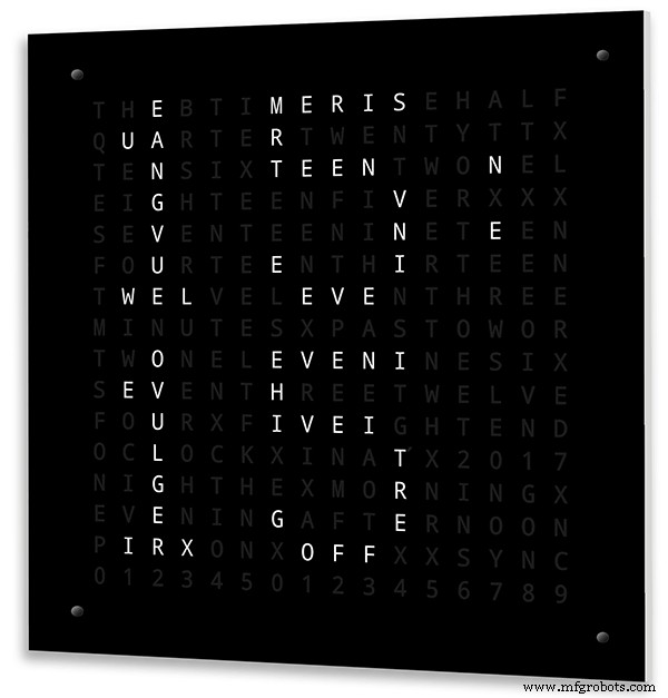
The WORDS are set in time.h
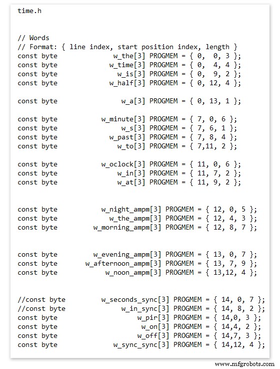
On line 52 we have
const byte w_the[3] PROGMEM ={ 0, 0, 3 };
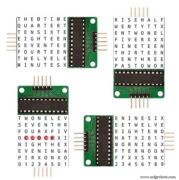
The word "THE" is described in this line with the LED location in the curly brackets "{ 0, 0, 3 }"
This is the co-ordinate of the LEDs we are gong to light when we call "w_the"
The LED matrix numbers starts top left and start from 0 so "{ 0, 0, 3 }" is the first LED across and down the 3 just means the 3 LEDs across including this one will light. As the letters THE are in this position the word "THE" is displayed.
Similarly the word "TIME" would be lit by lighting the four LEDs here { 0, 4, 4 } or row 0, 5th LED along and light 4 LEDs (remember to count from 0).
Working you way down the page shows the position of all the words.
Controlling when words are lit
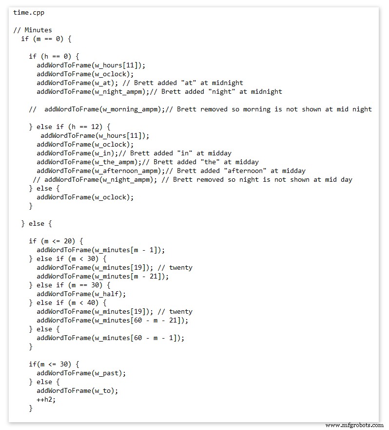
This happens in the module time.cpp
Here you just make a list of rules to tell the clock what words to light at certain times.
Pic above shows part of the code starting with line 695
At midnight we want to make the clock say "THE TIME IS TWELVE OCLOCK AT NIGHT"
Midnight is 00 00
"THE TIME IS" is always displayed from lines 687
So we add the rules if minutes are 0, then if hours are 0 show the word for hours "TWELVE" and the word "OCLOCK" the word "AT" and the word "NIGHT"
If you follow the code down all the possible time combinations are covered.
Analogue Clock Code Change - increase in time definition One of the comments sent to me by srdevil was some code changes. His comment can be seen below.
I have not had time to test the code but have included it below if you want to try it out.
" If the time is 18:00, it points up (long leg) and down (short leg). But when the time is 18:59, it still points totally down (short leg) so it looks like the time is 17:59 on a normal clock. My brother change the code so that if it is>HH:15 the small pointer moves already to the next number. As of this we also increased the resolution in the part between>HH:15 -
Code on the comments section or can be seen here http://home.btconnect.com/brettoliver1/Word_Clock/Word_Clock.htm#analogeclock
Código
- Brett_wordclock_v4_5.zip
Brett_wordclock_v4_5.zipArduino
Load into Aduino IDENo preview (download only).
Github
https://github.com/wouterdevinck/wordclockhttps://github.com/wouterdevinck/wordclockGithub
https://github.com/svcabre/wordclockhttps://github.com/svcabre/wordclockMy Word Clock on GITHUB
Schematics and code https://github.com/brettoliver/wordclockPiezas y carcasas personalizadas
Vinyl Sticker Design in Inkscape (free to download) change as required brett11_print_ready_6bbpMTDyFa.svgEsquemas
Schemaic showing main board connections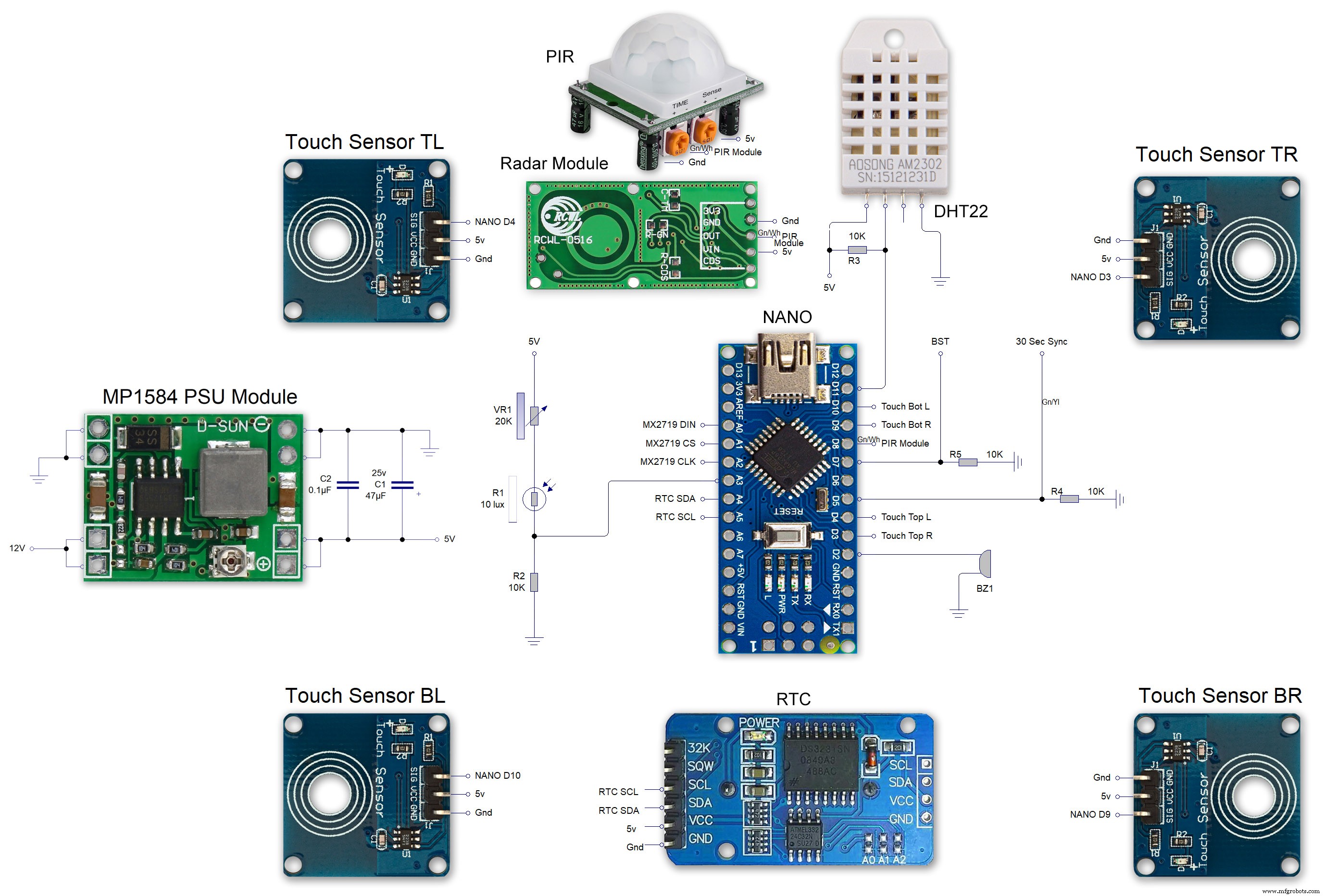 MAX7219 7 segment display module 01 LED connections
 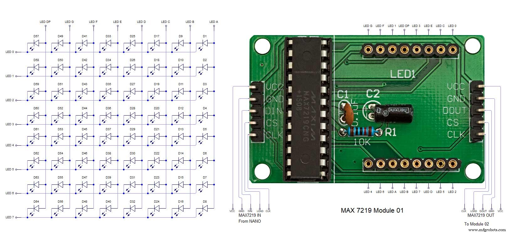 MAX7219 7 segment display module 02 LED connections
 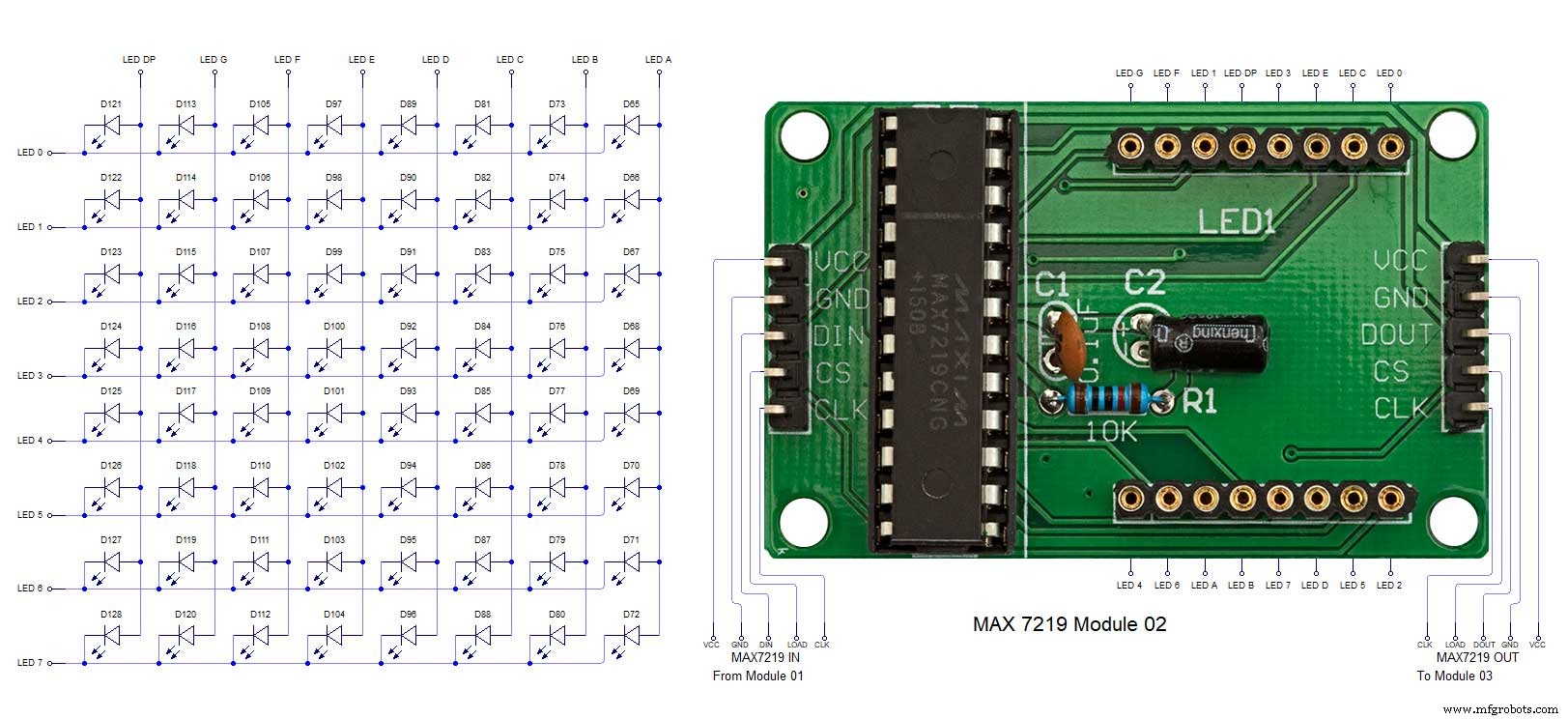 MAX7219 7 segment display module 03 LED connections
 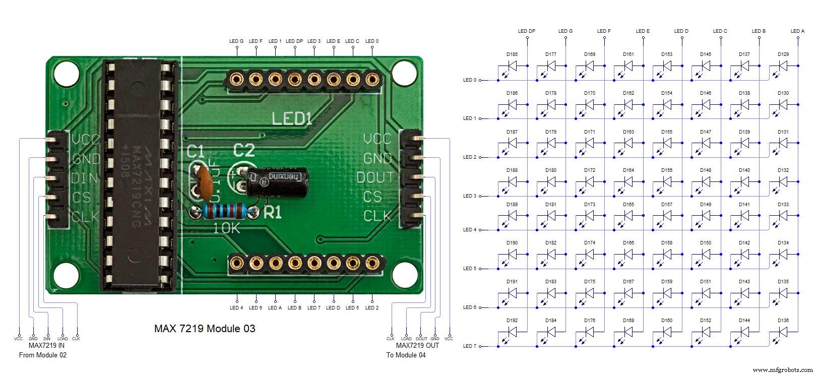 MAX7219 7 segment display module 04 LED connections
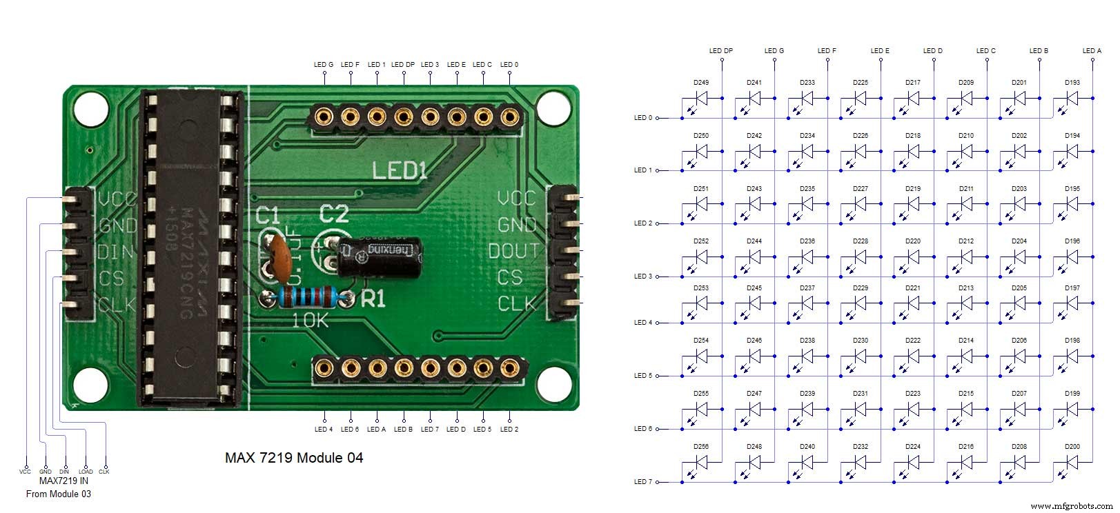
Proceso de manufactura
- Reloj de cuco
- Impresión 3D con silicona:¿llega su momento?
- Lectura de sensores analógicos con un pin GPIO
- El reloj IV9 Numitron más simple de bricolaje con Arduino
- Python Timeit() con ejemplos
- Reloj de palabras simple (Arduino)
- Reloj Arduino con tiempos de oración islámicos
- Reduzca los cuellos de botella con 5 herramientas sencillas
- Arduino Temp. Monitor y reloj en tiempo real con pantalla 3.2
- Reloj Word en italiano
- Reloj despertador simple con DS1302 RTC