


Barómetro Arduino
Componentes y suministros
 |
| × | 1 | |||
 |
| × | 1 |
Acerca de este proyecto
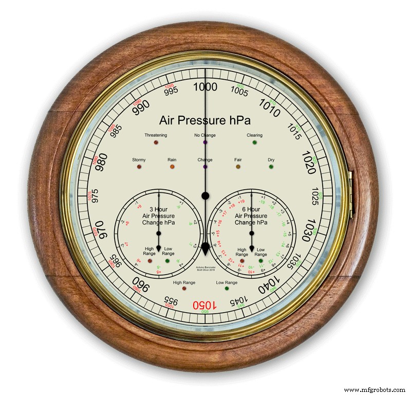
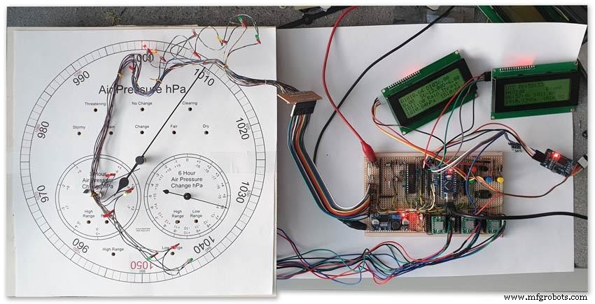
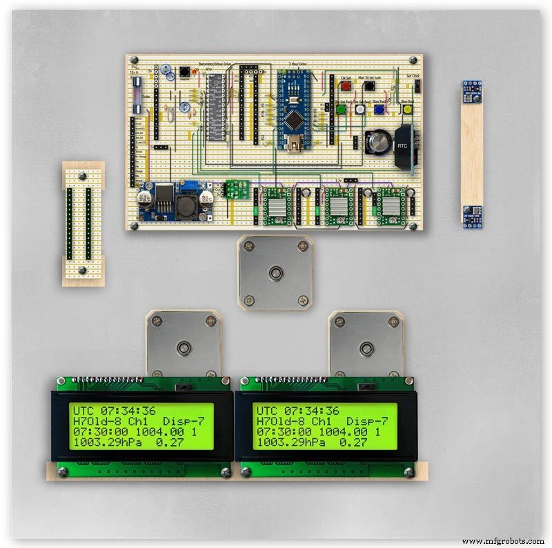
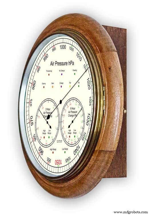
Usando un Arduino UNO y Nano para mostrar la presión del aire en una pantalla analógica de 12 "(300 m) usando 3 motores paso a paso.
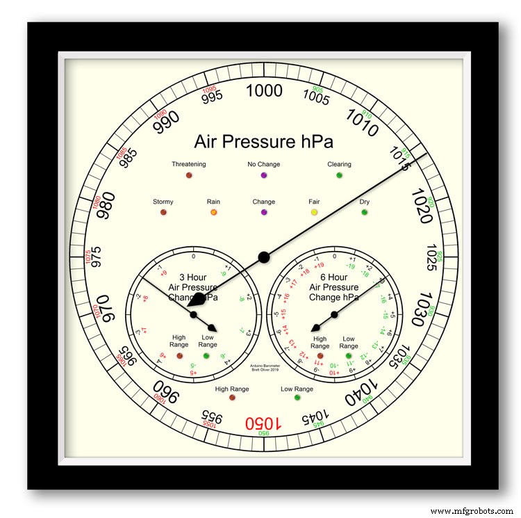
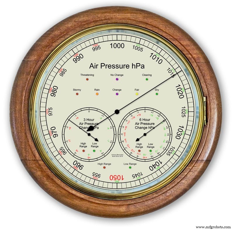
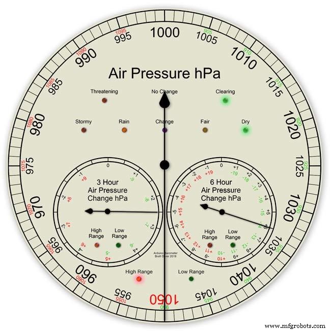
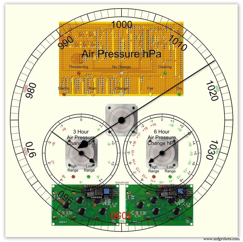
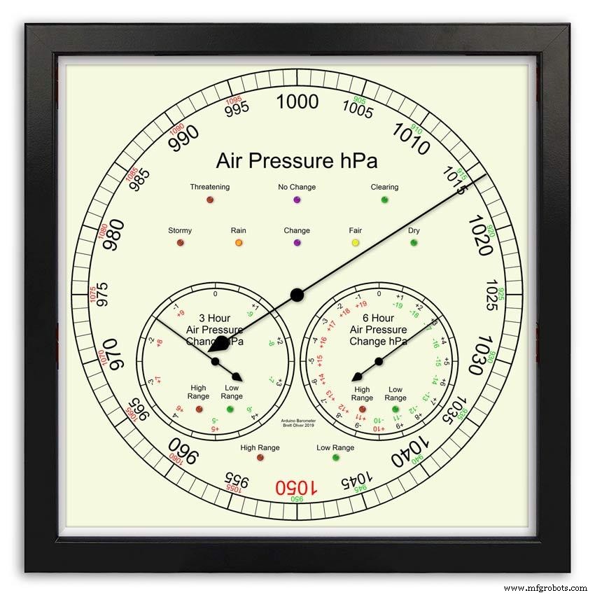
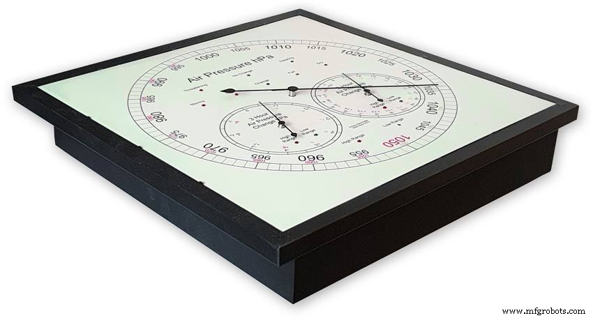
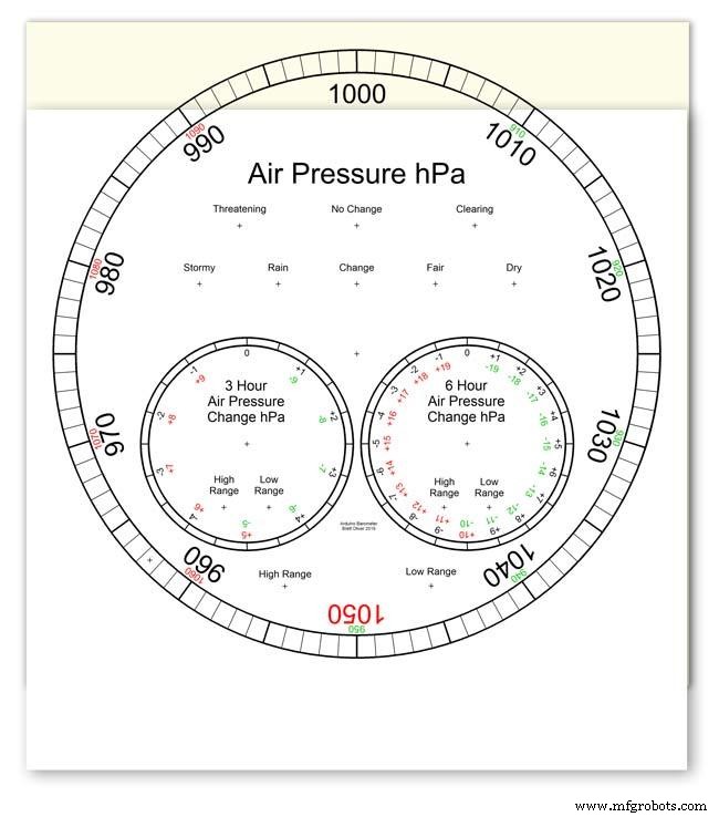
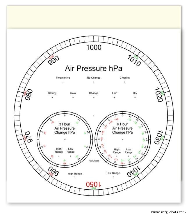
Se puede elegir entre 2 diseños de esferas, modernos y clásicos.
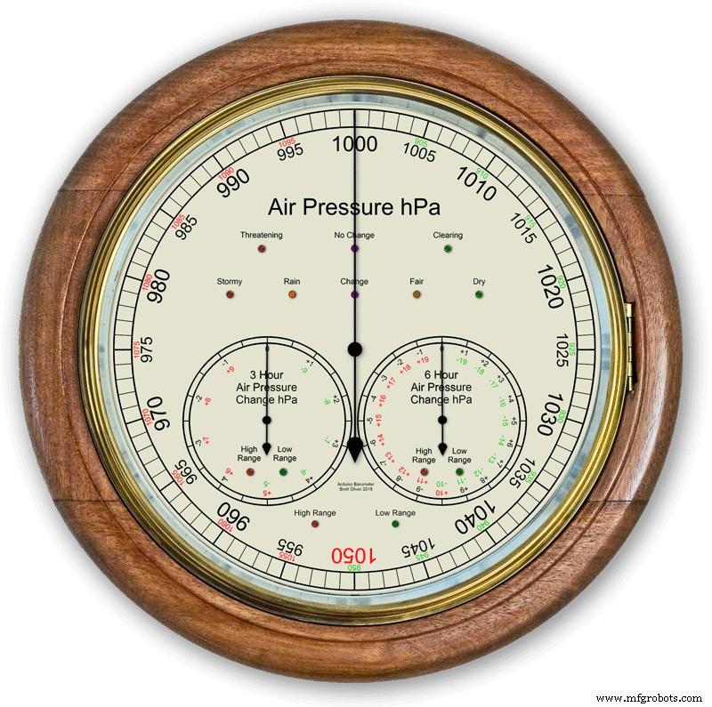
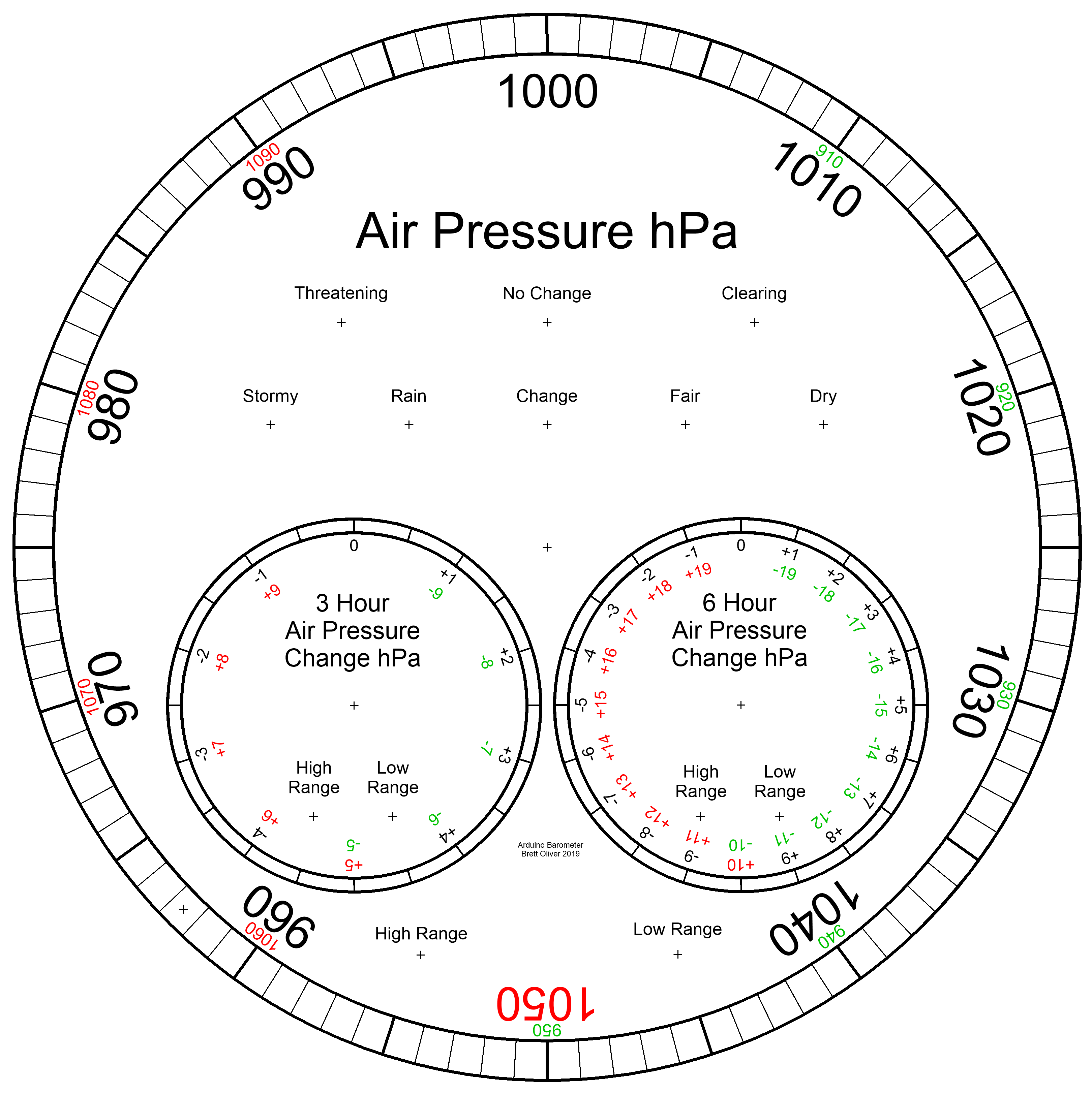
La presión del aire en hPa (hectopascal) se muestra en el dial principal grande y se actualiza cada 10 minutos.
Hay 2 diales secundarios, uno muestra el cambio de presión de las últimas 6 horas y el otro muestra el cambio de presión de las últimas 3 horas.
La esfera de 3 horas tiene una resolución aumentada de 0,5 hPa, ya que se utiliza para la predicción meteorológica. Hay LED para mostrar cuando el rango extendido está en uso en las tres pantallas y también LED para indicar el pronóstico del tiempo en la pantalla de 3 horas.
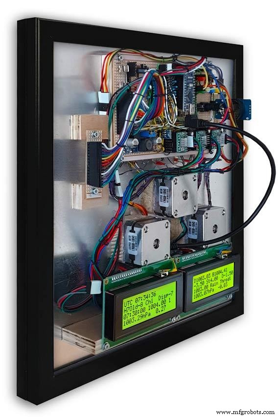
Dentro de la caja, dos pantallas LCD de 20x4 muestran información de cada uno de los microprocesadores.
La pantalla principal de presión de aire y la pantalla de 6 horas están controladas por un RTC. Este reloj también proporciona un pulso de 1 hora para la visualización de 3 horas.
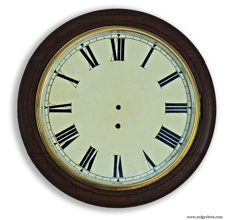
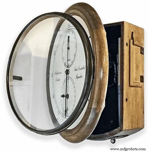
Paso 1:comparación con un barómetro analógico convencional

La mayoría de los barómetros analógicos pic. 2 simplemente use la presión del aire como una indicación para predecir el clima y debe recordar configurar el puntero móvil y anotar la hora a la que se configuró para ver el cambio de presión del aire.
El tiempo simplemente se escribe alrededor del dial y se lee desde el puntero. La previsión es un poco más complicada que ya que tiene que usar el segundo puntero y tomar nota de cualquier cambio durante un período de 3 horas. Tendrá que memorizar las combinaciones de presión actual y presión ascendente / descendente para obtener su pronóstico.
Mi barómetro monitorea continuamente el cambio de presión durante un período de 3 horas y 6 horas y muestra estas lecturas en 2 diales separados.
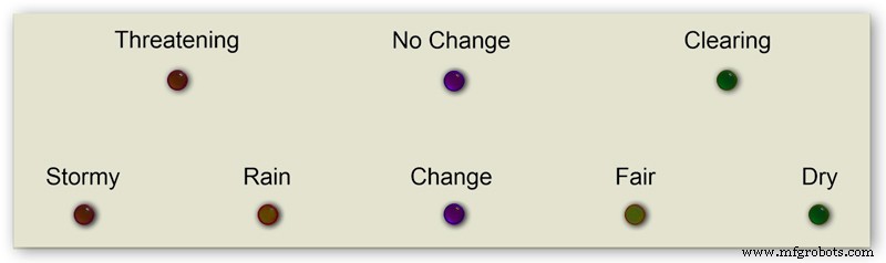
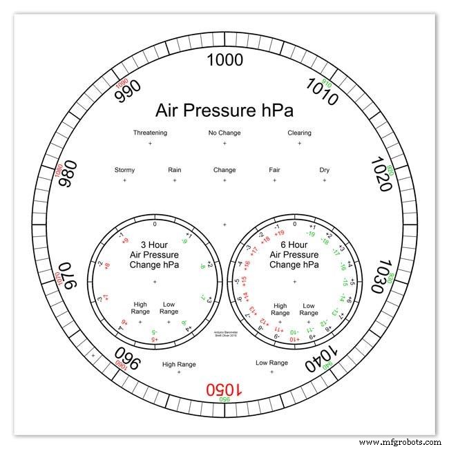
La imagen 1 muestra el rango de predicciones meteorológicas de mi barómetro.
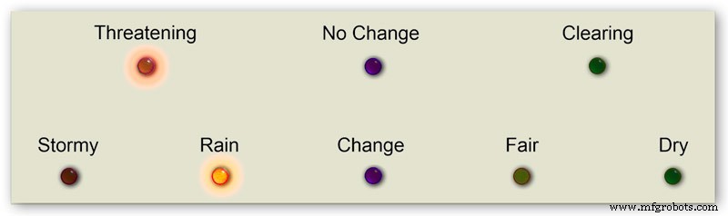
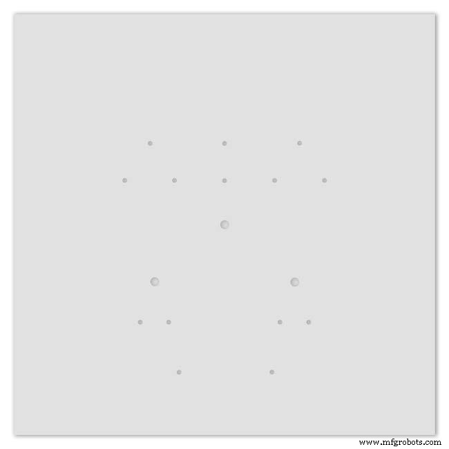
La imagen 3 muestra un primer plano de los LED de predicción del tiempo. La predicción meteorológica se basa en el cambio de presión atmosférica de las últimas 3 horas.
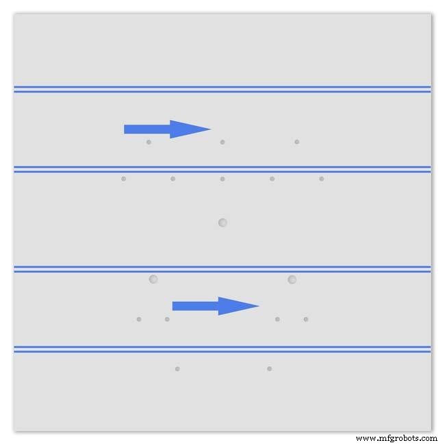
Paso 2:Demostración del barómetro para predecir una tormenta

Esta animación de lapso de tiempo muestra cómo las manecillas del barómetro y los LED de pronóstico reaccionan a una tormenta que se avecina.
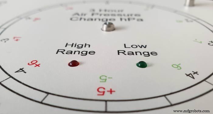
Paso 3:diales de rango extendido
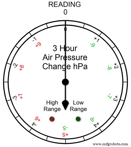

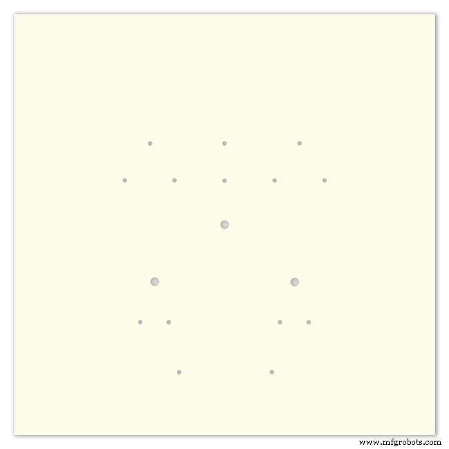
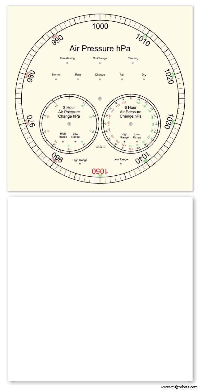
Los tres diales tienen rangos extendidos. Esto permite una resolución de visualización más grande en los diales para condiciones climáticas normales. En condiciones climáticas extremas, los diales cambian a rango extendido.
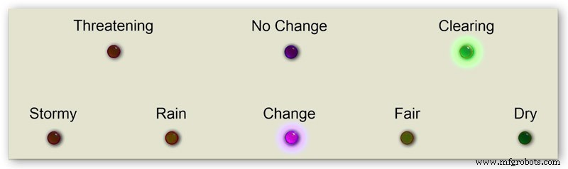
La animación pic1. muestra cómo se encienden los LED cuando el rango extendido está en funcionamiento. El LED rojo muestra cuando la lectura es de +5 o más. Luego leería las letras de la escala roja. El LED verde muestra cuando la lectura es -5 o menos. Luego leería las letras de la escala verde. Si la lectura va más allá del rango extendido, por ejemplo, en este dial por encima de +9 o -9, ambos LED se iluminarán para mostrar esto, consulte la siguiente sección.
Lecturas de presión en un rango extendido Figura 2 Si la lectura de presión está por encima del rango extendido + o -, ambos LED se encenderán para advertirle que se han producido lecturas extremas o cambios. Los diales todavía mostrarán las lecturas, por ejemplo, en el dial de 3 horas si la lectura fue -10, entonces el dial apuntaría a 0 con ambos LED encendidos. Si la lectura de 3 horas fue -11, entonces el dial apuntaría a -1 con ambos LED encendidos. Solo agrega 10 a la lectura.
En la siguiente animación, la diferencia de presión de 3 horas comienza en 0 y la diferencia de presión está disminuyendo. A -5 hPa, el LED verde se enciende para indicar que se está utilizando un rango extendido negativo. El cambio de presión sigue cayendo hasta que alcanza los -10hPa. Esto ahora está por encima del rango extendido, por lo que el LED rojo también se enciende. Luego, la presión vuelve a bajar a -11hPa y ambos LED permanecen encendidos. El cambio de presión comienza a disminuir a -10 hPa y, nuevamente, aún está por encima del rango extendido, por lo que ambos LED permanecen encendidos. Una vez que el cambio de presión desciende por debajo de -10, el LED rojo se apagará indicando que el rango extendido está nuevamente en uso.
Configuré el rango extendido en los diales después de verificar las extensiones meteorológicas en el Reino Unido y, aunque esperaba que se usaran los rangos extendidos de 3 horas y 6 horas, no pensé que el rango extendido se usaría en la pantalla principal del barómetro.
Imagen 3 Mientras creaba el prototipo del barómetro en enero de 2020, hubo una lectura récord alta de 1050 hPa en el sur de Inglaterra, mi barómetro principal entró en el rango extendido con el puntero en el 1050 rojo y el LED rojo de rango alto encendido.
Paso 4:Pantallas de información LCD
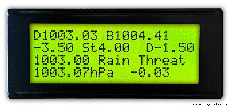
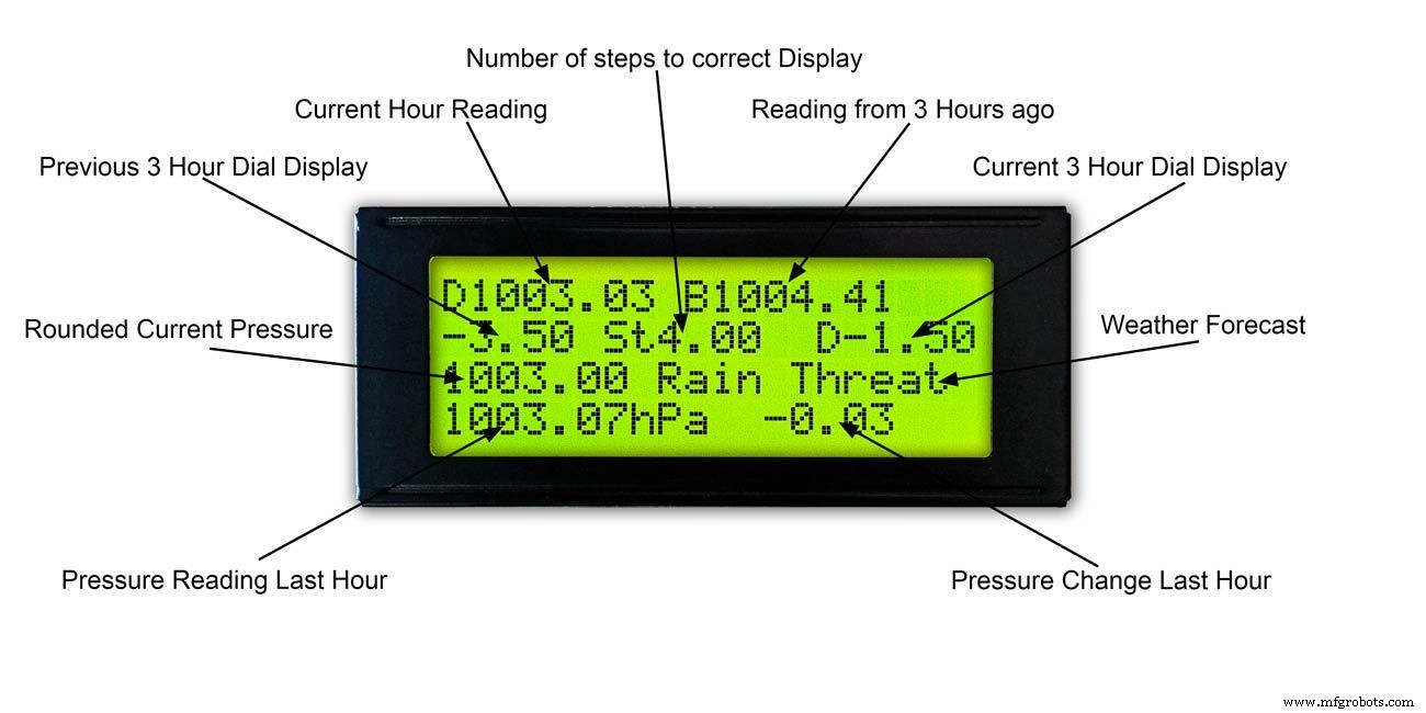
3 horas
Imagen 1 y 2 Esta pantalla muestra las lecturas de 3 horas y la información en el dial de 3 horas. También muestra el pronóstico del tiempo basado en la lectura actual y de las últimas 3 horas.
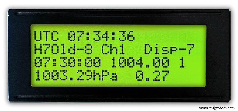
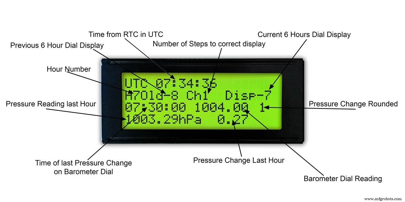
6 horas
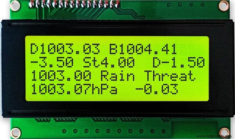
Foto. 3 y 4 Esta pantalla muestra las lecturas de la esfera del barómetro principal y también las lecturas de 6 horas.
Paso 5:predecir el clima

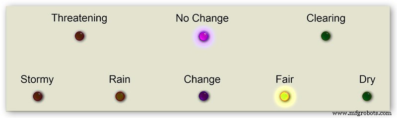


El pronóstico del tiempo en mi barómetro usa 8 LED.
Usando la presión del aire actual y la tasa de cambio durante las últimas 3 horas, el clima se predice en los LED.
La animación 1 muestra las diversas combinaciones de combinaciones de LED de pronóstico.
He visitado varios sitios meteorológicos y he recopilado la siguiente información sobre cómo predecir el tiempo con un barómetro.
Predecir el tiempo con el barómetro
Más específicamente, un barómetro con lecturas en hPa se puede interpretar de esta manera:
Si la lectura es superior a 1022 hPa
Presión en aumento o constante significa tiempo bueno continuo. Presión que cae lentamente significa tiempo bueno. Presión que cae rápidamente significa condiciones nubladas y más cálidas.
Si cae entre 1009 y 1022 hPa
Presión en aumento o constante significa que las condiciones actuales continuarán. Una presión que cae lentamente significa que el clima cambia poco. Una presión que cae rápidamente significa que es probable que llueva, o nieve si hace suficiente frío.
Si la lectura es inferior a 1009 hPa
La presión en aumento o constante indica que está despejado y un clima más fresco. La presión que cae lentamente indica lluvia Una presión que cae rápidamente indica que se avecina una tormenta.
El uso de la información de arriba de mi barómetro aplica la siguiente lógica para predecir el clima.
La lógica se aplica en la secuencia siguiente con los LED resultantes encendidos.
Imagen 2 Presión de aire <1009 hPa
La presión en aumento o constante indica que está despejado y un clima más fresco
Presión de aire <1009,00 y cambio de 3 horas> =0
Imagen 3 Presión de aire <1009 hPa
La presión que cae lentamente indica lluvia
Presión de aire <1009,00 y cambio de 3 horas <0 y cambio de 3 horas> =-1,5
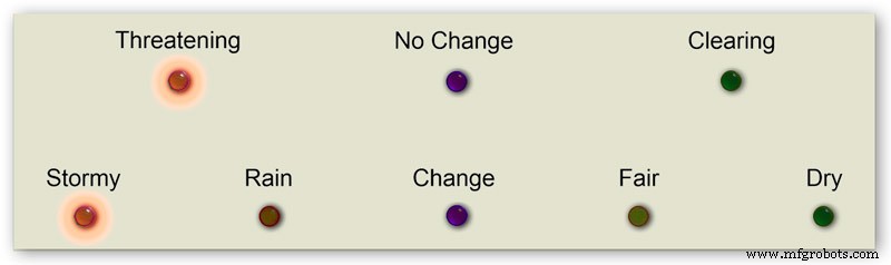
Imagen 4 Presión de aire <1009 hPa
La presión que cae rápidamente indica que se avecina una tormenta.
Presión de aire <1009,00 y cambio de 3 horas <-1,5
Imagen 5 La presión del aire está entre 1009 y 1022 hPa
La presión en aumento o constante significa que las condiciones actuales continuarán.
La presión que cae lentamente significa pocos cambios en el clima.
Presión de aire> =1009,00 y presión de aire <=1022,00 y cambio de 3 horas> =-1,5 y cambio de 3 horas <=1,5
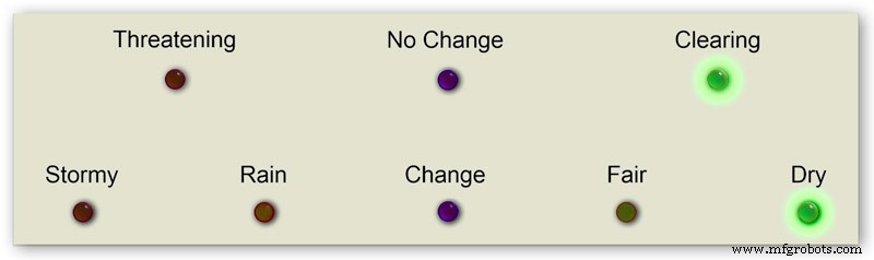
Figura 6 La presión del aire está entre 1009 y 1022 hPa
La presión del aire aumenta rápidamente significa que el clima se está despejando
Presión de aire> =1009,00 y presión de aire <=1022,00 y cambio de 3 horas> 1,5
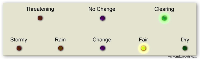
Figura 7 La presión del aire está entre 1009 y 1022 hPa
La presión que cae rápidamente significa que es probable que llueva o nieve si hace suficiente frío.
Presión de aire> =1009,00 y presión de aire <=1022,00 y cambio de 3 horas <-1,5
Imagen 8 Presión de aire superior a 1022 hPa
La presión en aumento o constante significa clima seco.
Presión de aire> 1022,00 y cambio de 3 horas> =0
Imagen 9 Presión de aire superior a 1022 hPa
La presión que cae lentamente significa buen tiempo.
Presión de aire> 1022,00 y cambio de 3 horas <0 y cambio de 3 horas> =-1,5
Imagen 10 Presión de aire superior a 1022 hPa
La presión que cae rápidamente significa un cambio
Presión de aire> 1022.00 &&cambio de 3 horas <-1.5
Paso 6:inicio del barómetro
En el encendido inicial se realiza una prueba de LED.
Una vez completadas, las manecillas pasarán a su configuración inicial y estarán listas para ser calibradas.
Paso 7:Configuración de inicio inicial RTC
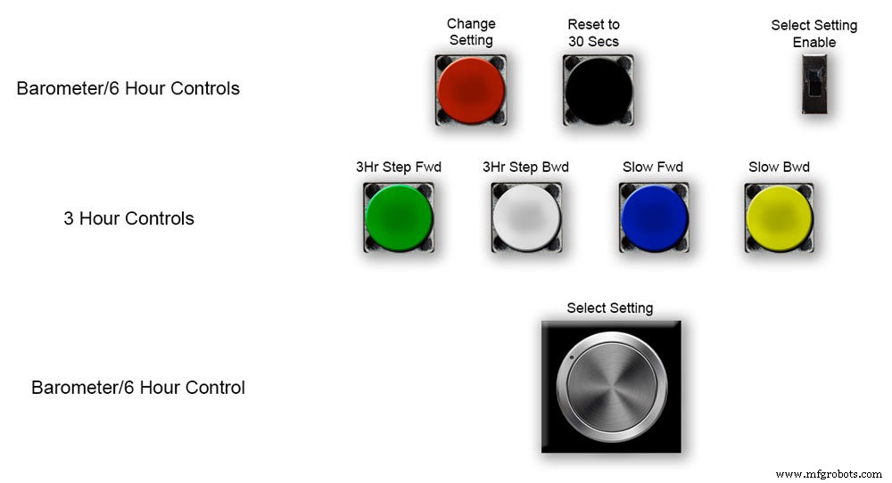


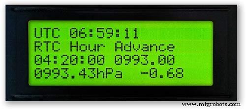
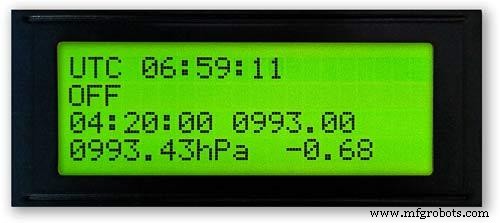
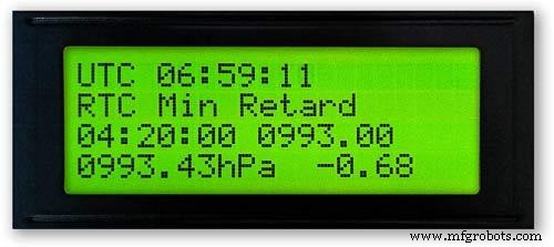

Imagen 1 En el encendido inicial, el barómetro deberá configurarse utilizando los controles de la placa Vero.
RTC
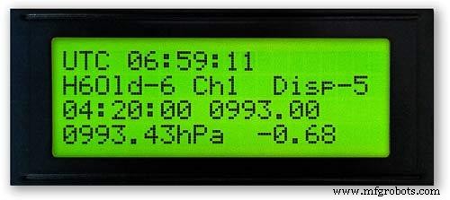
Imagen 2 El RTC deberá configurarse en la hora correcta. Lo configuro en UTC y no me molesto en cambiar a la hora de verano. Antes de ajustar el tiempo, anote el valor "Disp" en este caso -5. Este es el valor de la manecilla de las 6 horas y se necesitará más adelante en la configuración. Deslice el interruptor "Seleccionar configuración habilitada" a la posición de encendido. La pantalla no cambiará.
Imagen 3 Gire lentamente la perilla "Seleccionar ajuste" en el sentido de las agujas del reloj y la segunda fila de la pantalla LCD principal cambiará.
Deténgase cuando la pantalla muestre "RTC Hour Retard". Si desea retrasar las horas RTC, presione el botón rojo "Change setting". Un solo clic hará retroceder las horas. Varios clics reducirán la cantidad de clics presionados, pero se necesitará un segundo para actualizar el RTC.
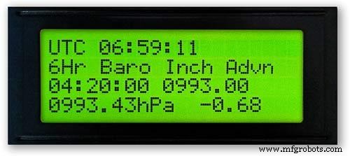
Imagen 4 Si gira más la perilla "Seleccionar ajuste", la pantalla cambiará a "Avance de hora RTC"
Si desea adelantar las horas de RTC, presione el botón rojo "cambiar configuración". Un solo clic avanzará las horas. Varios clics avanzarán la cantidad de clics presionados, pero se necesitará un segundo para actualizar el RTC.
Imagen 5 Si gira más la perilla "Seleccionar ajuste", la pantalla cambiará a "RTC Min Retard"
Si desea retrasar los minutos de RTC, presione el botón rojo "cambiar configuración". Un solo clic hará retroceder los minutos. Varios clics reducirán la cantidad de clics presionados, pero se necesitará un segundo para actualizar el RTC.
Imagen 6 Si gira más la perilla "Seleccionar ajuste", la pantalla cambiará a "RTC Min Advance"
Si desea avanzar los minutos de RTC, presione el botón rojo "cambiar configuración". Un solo clic avanzará los minutos. Varios clics avanzarán la cantidad de clics presionados, pero se necesitará un segundo para actualizar el RTC.
Imagen 7 Una vez que haya completado la configuración de RTC o cualquier otra configuración, devuelva la perilla "Seleccionar configuración" completamente en sentido antihorario hasta que la pantalla muestre "Apagado"
Deslice el interruptor "Seleccionar configuración habilitada" a la posición de apagado.
Nota. Los segundos se pueden sincronizar a 30 segundos en cualquier momento presionando el botón negro "Restablecer a 30 segundos". El tiempo ahora se recordará en el RTC si se apaga la energía.
Paso 8:Configuración de inicio inicial Manecilla de 6 horas


Ajuste de la manecilla de las 6 horas
Imagen 1 Una vez que se configura el RTC, es necesario configurar el barómetro y las manecillas de presión de aire de 6 horas.
Deslice el interruptor "Seleccionar configuración habilitada" a la posición de encendido. La pantalla no cambiará.
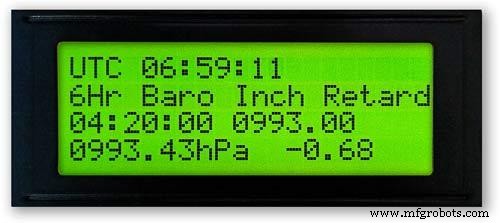
Gire lentamente la perilla "Seleccionar ajuste" en el sentido de las agujas del reloj hasta que se muestre "6Hr Baro Inch Retard".
En el primer encendido, la manecilla de las 6 horas deberá calibrarse al dígito más cercano.
Si el dígito más cercano está detrás de la manecilla, presione el botón rojo "cambiar configuración". Un solo clic moverá la mano hacia atrás paso a paso. Si mantiene presionado el botón, la mano retrocederá varias veces. Una vez que la mano esté exactamente en un dígito, suelte el botón.
Imagen 2 Si el dígito más cercano al frente de la mano o si ha retrasado demasiado la mano usando lo anterior, gire la perilla "Seleccionar ajuste" en el sentido de las agujas del reloj hasta que se muestre "6Hr Baro Inch Advn".
Presione el botón rojo "cambiar configuración". Un solo clic hará que la mano avance paso a paso. Si mantiene presionado el botón, la mano avanzará lentamente varias veces. Una vez que la mano esté exactamente en un dígito, suelte el botón.
Imagen 3 Una vez que la manecilla de las 6 horas se ha establecido exactamente en un dígito, la manecilla de las horas debe establecerse en el valor correcto.
Antes de ajustar el RTC, anotó este número -5.
Imagen 4 Si la manecilla de visualización de 6 horas está demasiado avanzada.
Gire la perilla "Seleccionar ajuste" en el sentido de las agujas del reloj hasta que se muestre "6Hr Baro Retard". Presione y suelte el botón rojo "cambiar configuración". Este alféizar hace que la manecilla de las 6 horas retroceda 1 unidad entera. Deténgase cuando la manecilla de las 6 horas llegue a su número anotado.
Imagen 5 Si la manecilla de visualización de 6 horas está retrasada.
Gire la perilla "Seleccionar ajuste" en el sentido de las agujas del reloj hasta que se muestre "6Hr Baro Advance". Presione y suelte el botón rojo "cambiar configuración". Este paso adelanta la manecilla de las 6 horas 1 unidad completa. Deténgase cuando la manecilla de las 6 horas llegue a su número anotado.
Imagen 6 Tenga en cuenta que la pantalla de 6 horas tardará 8 horas en mostrarse correctamente, ya que necesitará almacenar lecturas en la memoria durante ese período de tiempo.
Siempre puede agregar las lecturas de presión de aire anteriores en el código antes de cargar si necesita que la pantalla de 6 horas funcione desde el inicio.
El código convierte las horas en un número H como se muestra arriba de H =6. En la línea de código 128 H6 significará poner la lectura de la hora actual debajo de la hora 6 la lectura anterior en la hora 7 la lectura anterior en la hora 0, etc.
int hora0 =1015;
int hora1 =1016
; int hora2 =1015;
int hora3 =1016;
int hora4 =1016
; int hora5 =1016;
int hora6 =1012;
int hora7 =1013;
Debería poder obtener sus lecturas locales de Internet.
Configuré una página de mi estación meteorológica para poder verificar esto mientras construyo el barómetro.
Haga clic en este enlace para ver los cambios por hora en Kenley Surrey, Reino Unido.
Paso 9:Configuración de inicio inicial Mano del barómetro principal


Ajuste de la manecilla del barómetro principal
Imagen 1 Ahora que la visualización de 6 horas es correcta, la manecilla del barómetro principal deberá ajustarse a la presión redondeada al nivel del mar en la tercera fila hacia abajo en la pantalla LCD principal.
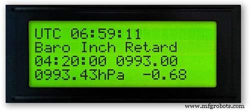
En el primer encendido, la manecilla del barómetro principal deberá calibrarse al dígito más cercano. Gire la perilla "Seleccionar ajuste" en el sentido de las agujas del reloj hasta que se muestre "Baro Inch Retard".
Si el dígito más cercano está detrás de la manecilla, presione el botón rojo "cambiar configuración". Un solo clic moverá la mano hacia atrás paso a paso. Si mantiene presionado el botón, la mano retrocederá varias veces. Una vez que la mano esté exactamente en un dígito, suelte el botón.
Imagen 2 Si el dígito más cercano frente a la mano o si ha retrasado la mano usando lo anterior demasiado, gire la perilla "Seleccionar ajuste" en el sentido de las agujas del reloj hasta que se muestre "Baro Inch Advn".
Presione el botón rojo "cambiar configuración".
Un solo clic hará que la mano avance paso a paso. Mantener presionado el botón hará que la mano avance hacia adelante repetidamente. Una vez que la mano esté exactamente en un dígito, suelte el botón.
Imagen 3 Si la manecilla del barómetro principal está demasiado avanzada.
Gire la perilla "Seleccionar ajuste" en el sentido de las agujas del reloj hasta que se muestre "Retardo del barómetro".
Presione y suelte el botón rojo "cambiar configuración".
Esto hará que la manecilla del barómetro principal retroceda 1 unidad completa. Deténgase cuando la manecilla de las horas alcance la presión redondeada al nivel del mar indicada.
Imagen 4 Si la manecilla del barómetro principal está retrasada en comparación con la presión redondeada al nivel del mar indicada.
Gire la perilla "Seleccionar ajuste" en el sentido de las agujas del reloj hasta que se muestre "Avance del barómetro".
Presione y suelte el botón rojo "cambiar configuración".
Esto hará avanzar la mano del barómetro principal 1 unidad completa. Deténgase cuando la mano alcance la presión redondeada al nivel del mar indicada.
Paso 10:Configuración de inicio inicial Manecilla de 3 horas


Ajuste de la manecilla de las 3 horas.
Oic.1 El ajuste de la manecilla de las 3 horas se realiza mediante los cuatro botones Verde, Blanco, Azul y Amarillo en el tablero Vero.
En el encendido inicial, la manecilla de las 3 horas deberá calibrarse a la unidad o media unidad más cercana.
Figura 2 Si el valor unitario de la manecilla de 3 horas más cercana está por delante de la manecilla de 3 horas, presione el botón amarillo "Slow Bwd" para mover la manecilla hacia atrás. Mantener el botón presionado hará que la mano retroceda varias veces.
Si el valor unitario más cercano de la manecilla de 3 horas está detrás de la manecilla de 3 horas, presione el botón azul "Avance lento" para mover la manecilla hacia adelante. Mantener el botón presionado hará que la mano avance varias veces.
Una vez que la manecilla de las 3 horas esté exactamente en una unidad / media unidad, la manecilla se puede establecer en el valor "D" en la pantalla LCD de 3 horas.
Si la manecilla está por delante del valor "D", presione el botón blanco "3Hr Step Bwd" para mover la manecilla de las 3 horas en medias unidades hacia atrás.
Si en la manecilla está en menos del valor "D", presione el botón verde "3Hr Step Fwd" para avanzar la manecilla de 3 horas en medias unidades hacia adelante.
Tenga en cuenta que la pantalla de 3 horas tardará 4 horas en mostrarse correctamente, ya que necesitará almacenar lecturas en la memoria durante ese período de tiempo.
Siempre puede agregar las lecturas de presión de aire anteriores en el código antes de cargar si necesita el pronóstico y la pantalla de 3 horas para que funcionen desde el inicio.
Código de visualización de 3 horas en la línea 124
float hour0 es la hora actual
float hour1 es la hora anterior, etc., etc.
hora flotante0 =1036.00;
hora flotante1 =1036,00;
hora flotante2 =1036,00;
hora flotante3 =1036,00;
hora flotante4 =1036.00;
Debería poder obtener sus lecturas locales de Internet.
Paso 11:Módulos / Componentes

Módulos
Siempre que sea posible, este proyecto utiliza módulos prediseñados para ahorrar tiempo de construcción y diseño.
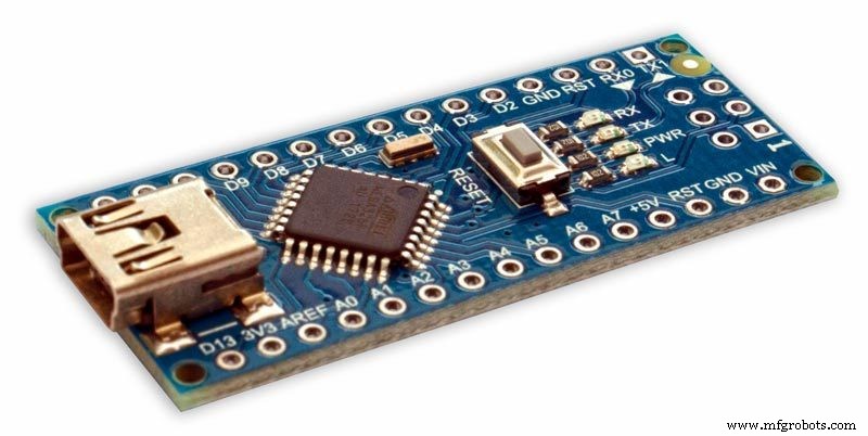
Microprocesadores
Este proyecto utiliza 2 microprocesadores, un Atmega 328 (UNO) pic.1 y un Arduino Nano pic.2. He usado esta combinación porque ya había construido un 328 a partir de otro proyecto y debido al espacio limitado en la placa Vero también agregué el Nano.
Energía
El barómetro usa alrededor de 65 mA y esto aumentará un poco a medida que cada motor avance durante una fracción de segundo cada 10 minutos a una hora
AMS117 imagen 3
El módulo de este proyecto es de 3.3v y se utiliza para alimentar el módulo BMP180.
La serie AMS1117 de reguladores de voltaje fijos y ajustables están diseñados para proporcionar hasta 1 A de corriente de salida y para operar hasta 1 V diferencial de entrada a salida. El voltaje de caída del dispositivo está garantizado como máximo 1.3V, disminuyendo a corrientes de carga más bajas. El ajuste en chip ajusta el voltaje de referencia al 1.5%. El límite de corriente se establece para minimizar la tensión en condiciones de sobrecarga tanto en el regulador como en los circuitos de la fuente de alimentación. El módulo de este proyecto es de 3.3v y se utiliza para alimentar el módulo BMP180.
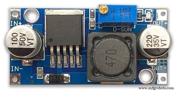
Convertidor LM2596 Buck DC a DC 3.0-40V a 1.5-35V pic.4Este módulo convierte la entrada de 12v a 5v
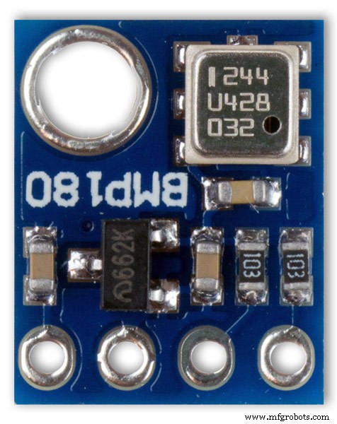
Módulo de sensor de presión BMP180 2 de imagen 5 El BMP180 Breakout es un sensor de presión barométrica con una interfaz I2C ("Cable"). Los sensores de presión barométrica miden la presión absoluta del aire a su alrededor. Esta presión varía tanto con el clima como con la altitud. Dependiendo de cómo interprete los datos, puede monitorear los cambios en el clima, medir la altitud o cualquier otra tarea que requiera una lectura de presión precisa.
Conecte los pines +, -, CL y DA a su Arduino.
CL pasa a SCL y DA pasa a SDA.
IMPORTANTE:Conecte las clavijas de alimentación (+ y -) ÚNICAMENTE a una fuente de 3.3V. Los voltajes más grandes dañarán permanentemente la pieza. Tenga en cuenta que debido a que I2C usa controladores de drenaje abiertos, es seguro conectar los pines I2C (DA y CL) a un puerto I2C en un microprocesador de 5V.
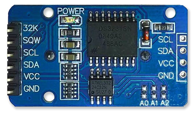
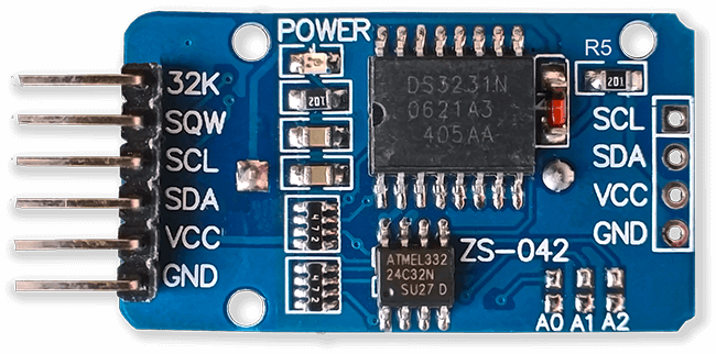
Imagen del reloj en tiempo real RTC.6
Este brómetro utiliza un módulo de reloj de precisión en tiempo real DS3231 AT24C32 I2C.
Este módulo se utiliza principalmente para cronometraje, pero también proporciona marcas de tiempo en la pantalla LCD. La hora está configurada en UTC y no se cambia para el verano. El módulo se suministra con una batería recargable de iones de litio (consulte el diagrama de arriba). Utilizo una batería no recargable, por lo que quité la resistencia R5 del módulo; consulte la sección Modificación de RTC para obtener más detalles.
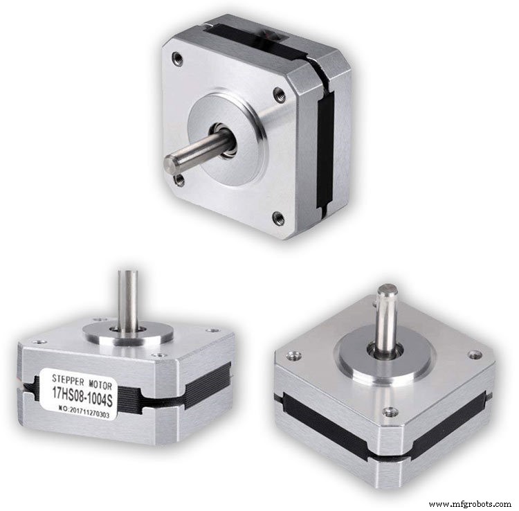
Motores paso a paso 3 desactivados El barómetro usa 3 motores paso a paso Nema 17 1A, 13N.cm Holding Torque, 4-Lead, 1.8 ° Usé motores 1.8 ° ya que los pasos encajan exactamente en 360 ° 200 veces. Puede usar motores Nema 8 si lo desea, pero no use motores 28BYJ-48-5V ya que no tienen el ángulo de paso de 1.8 ° requerido.
Se requiere el ángulo de paso de 1.8 ° ya que se divide exactamente en 360 ° para los diales de mi barómetro.
Pantallas LCD 2 apagadas
He utilizado 2 pantallas LCD de 20x4, una para el barómetro, el reloj y la visualización de 6 horas y la otra para la visualización de 3 horas y el pronóstico.
Paso 12:Módulos / Componentes A4988 Controlador de motor paso a paso
Controlador de motor paso a paso bipolar micropasos A4988 3 apagado
Importante, lea atentamente esta sección
Mi barómetro está configurado en una rotación de 1/16 y el código se ajusta en consecuencia.
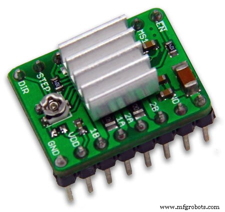
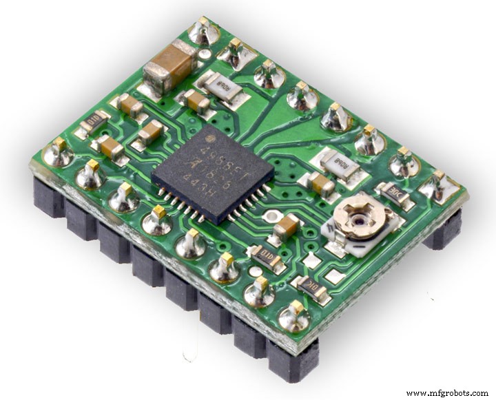
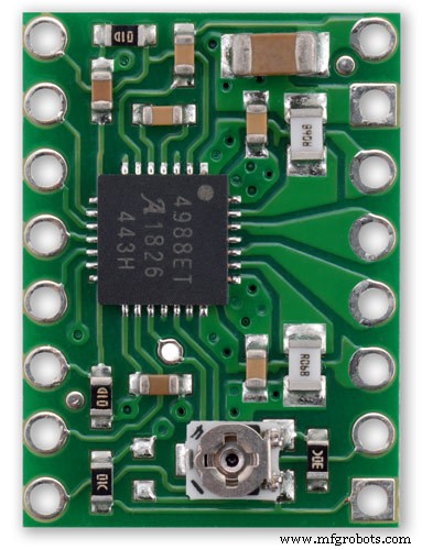
Controlador de motor paso a paso bipolar de micropasos A4988 pic.1 con y pic.2 sin disipador de calor
Esta placa de conexión para el controlador de motor paso a paso bipolar de micropasos A4988 de Allegro cuenta con limitación de corriente ajustable, protección contra sobrecorriente y sobrecalentamiento, y cinco resoluciones de micropasos diferentes (hasta 1/16 de paso).
Opera de 8 V a 35 V y puede entregar aproximadamente 1 A por fase sin un disipador de calor o flujo de aire forzado (tiene una capacidad nominal de 2 A por bobina con suficiente enfriamiento adicional).
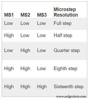
Estas son algunas de las características clave del controlador:Interfaz de control de dirección y paso simple Cinco resoluciones de paso diferentes:paso completo, medio paso, cuarto de paso, octavo paso y decimosexto paso El control de corriente ajustable le permite establecer la salida de corriente máxima con un potenciómetro, que le permite usar voltajes por encima del voltaje nominal de su motor paso a paso para lograr velocidades de paso más altas Control de corte inteligente que selecciona automáticamente el modo de caída de corriente correcto (caída rápida o caída lenta) Apagado térmico por sobrecalentamiento, bloqueo por bajo voltaje y protección de corriente cruzada Protección de cortocircuito a tierra y de carga en cortocircuito
Conexiones de alimentación El controlador requiere que se conecte una tensión de alimentación lógica (3 - 5,5 V) a través de los pines VDD y GND y que se conecte una tensión de alimentación del motor (8 - 35 V) a través de VMOT y GND. Estos suministros deben tener condensadores de desacoplamiento apropiados cerca de la placa y deben ser capaces de entregar las corrientes esperadas (picos de hasta 4 A para el suministro del motor).
Advertencia:esta placa portadora utiliza condensadores cerámicos de baja ESR, lo que la hace susceptible a picos de voltaje destructivos de LC, especialmente cuando se utilizan cables de alimentación de más de unas pocas pulgadas. En las condiciones adecuadas, estos picos pueden exceder la clasificación de voltaje máximo de 35 V para el A4988 y dañar permanentemente la placa, incluso cuando el voltaje de suministro del motor es tan bajo como 12 V. Una forma de proteger al controlador de tales picos es colocar un condensador electrolítico grande (al menos 47 µF) a través de la potencia del motor (VMOT) y tierra en algún lugar cercano a la placa.
Conexiones de motor
El A4988 puede accionar motores paso a paso de cuatro, seis y ocho cables si están conectados correctamente. Warning:Connecting or disconnecting a stepper motor while the driver is powered can destroy the driver. (More generally, rewiring anything while it is powered is asking for trouble.)
Step (and microstep) size
see table pic. 3Stepper motors typically have a step size specification (e.g. 1.8° or 200 steps per revolution), which applies to full steps. A microstepping driver such as the A4988 allows higher resolutions by allowing intermediate step locations, which are achieved by energizing the coils with intermediate current levels. For instance, driving a motor in quarter-step mode will give the 200-step-per-revolution motor 800 microsteps per revolution by using four different current levels.
The resolution (step size) selector inputs (MS1, MS2, and MS3) enable selection from the five step resolutions according to the table below. MS1 and MS3 have internal 100kΩ pull-down resistors and MS2 has an internal 50kΩ pull-down resistor, so leaving these three microstep selection pins disconnected results in full-step mode. For the microstep modes to function correctly, the current limit must be set low enough (see below) so that current limiting gets engaged. Otherwise, the intermediate current levels will not be correctly maintained, and the motor will skip microsteps.
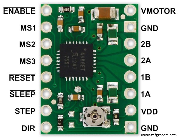
Control inputs
pics 4 &5Each pulse to the STEP input corresponds to one microstep of the stepper motor in the direction selected by the DIR pin. Note that the STEP and DIR pins are not pulled to any particular voltage internally, so you should not leave either of these pins floating in your application.
If you just want rotation in a single direction, you can tie DIR directly to VCC or GND. The chip has three different inputs for controlling its many power states:RST, SLP, and EN. For details about these power states, see the datasheet.
Please note that the RST pin is floating; if you are not using the pin, you can connect it to the adjacent SLP pin on the PCB to bring it high and enable the board.
Current LImiting Before connecting the motor we should adjust the current limiting of the driver so that we are sure that the current is within the current limits of the motor. We can do that by adjusting the reference voltage using the potentiometer on the module to set the VRef.
See details on the video link pic. 6
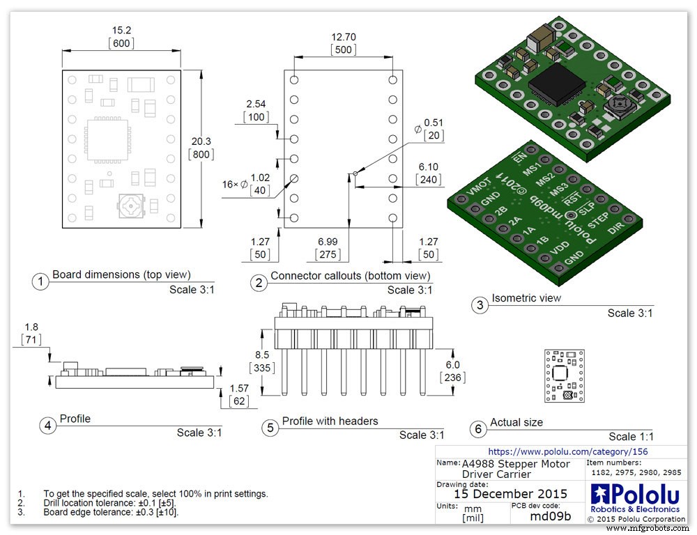
Manufacturers Drawing sheet pic.7
Step 13:Construction Prototyping
The circuit was prototyped using a hardboard dial with holes drilled for the motor spindles and LEDs.
Various dial designs were then printed on normal paper and Sellotaped over the top. The LED wiring loom was made with the LEDs in position on the temporary dial.
If you are using the round dial design this will allow you to check if the board etc will be mounted on the dial or in the back box.
Step 14:Construction RTC Modification
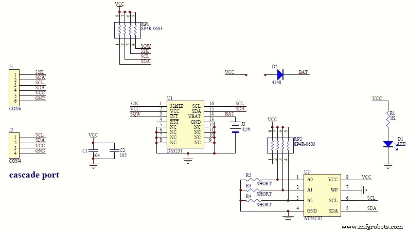
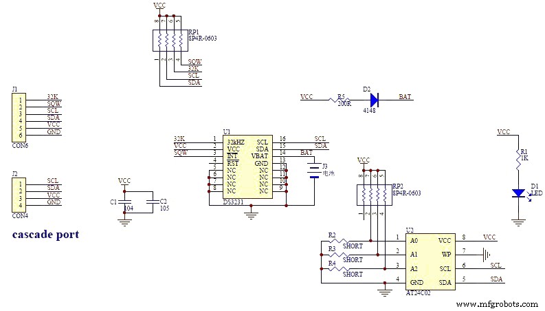
The module comes supplied with a Lithium-Ion rechargeable battery see diagram pic. 2.
I use a non rechargeable battery (I am not happy with the circuit design with a lithium-iron battery and associated fire risk) of the so have removed resistor R5 from the module as below. This stops any charge current to the battery.
Pic.3 shows the module without the resistor (just break it off) and pic.4 the modified circuit.
Step 15:Construction Mounting Modules &Boards
On the modern square dial design all the modules and boards are mounted on the dial. The classic round dial desgn will need some parts mounted in the back box as there is less space on the dial.
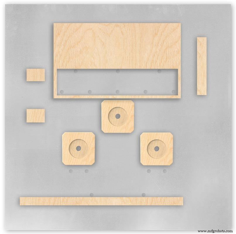
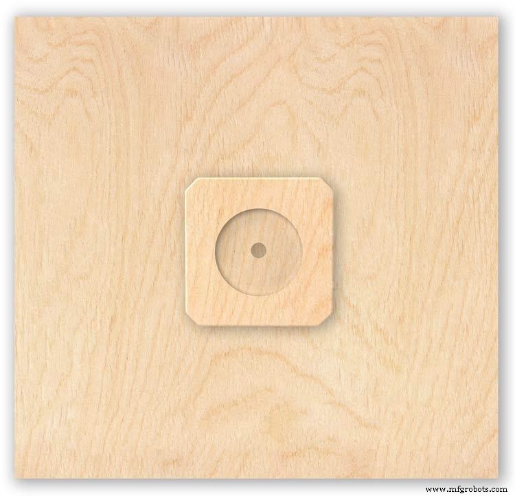
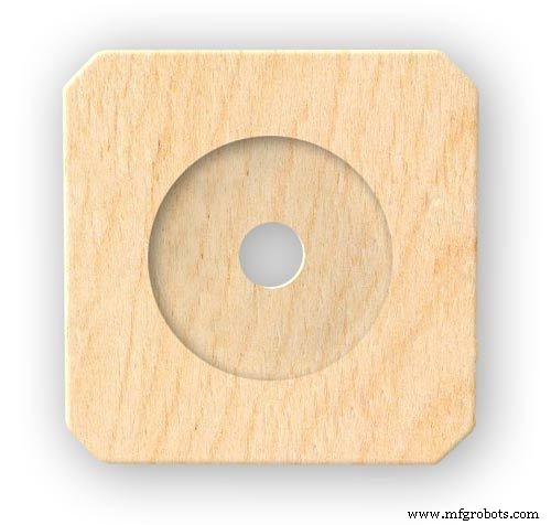
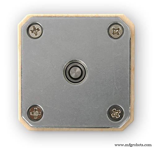
Motors are hot melt glued to wooden mounting blocks pic.1&2. The wooded blocks are cut fron a sheet of plywood pic.3. The mounting blocks depths are set to allow the correct protrusion of the spindles through the dial. I have hot melt glued the blocls to the dial.
The Vero Boards and LCD displays are also screwed to wooden blocks which have been glued to the dial using impact adhesive.
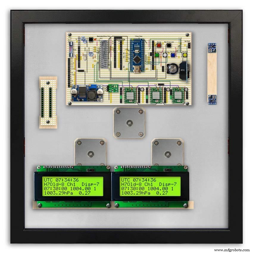
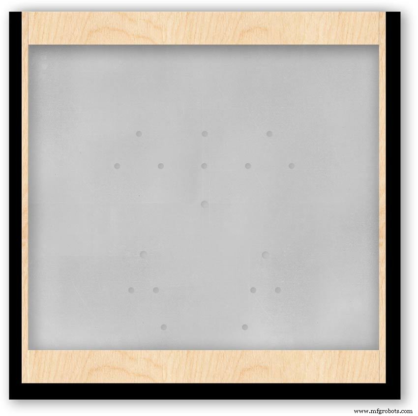
Pic.4 shows the front view with a transparent dial showing mounting locations.
Foto. 5 shows the same but the rear view.
Pic.6 shows the wooden mounting blocks locations and layout.
Pic.7 shows the modules and motors mounted on the blocks.
Step 16:Construction LED Fixing

The 3mm LEDs are mounted so they just show above the surface of the dial pic.1.
3mm holes are drilled and hot melt glue holds them in place.
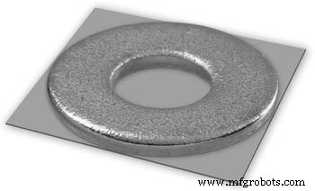
To get a uniform depth I made a jig using a washer and piece of card glued to it pic.2.When fixing the LEDs the jig is pressed against the dial with the depth of the washer setting the protrusion of the LED through the dial.
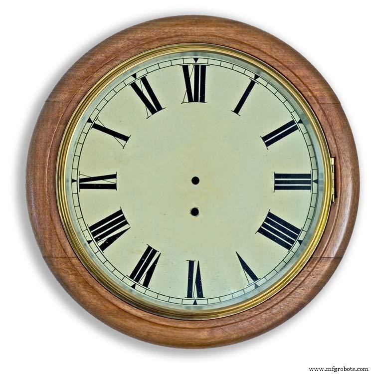
Step 17:Construction Classic Style English Dial Clock Case
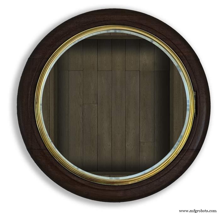
The classic 12" Dial Clock case can be purchased from Ebay as "case only" pic.1.
Various styles are available this one is oak and has a dial surround that hinges away from the back box pic.2.
This makes for a very easy build as all the hard work has been done. The dial is mounted by 3 small wood screws hidden behind the brass dial bezel.
This dial surround has been stripped and bleached to bring out the original light colour of the wood pic.3.The dial was removed as it had a winding hole off center.
A new dial was cut from a sheet of alluminium pic.4.
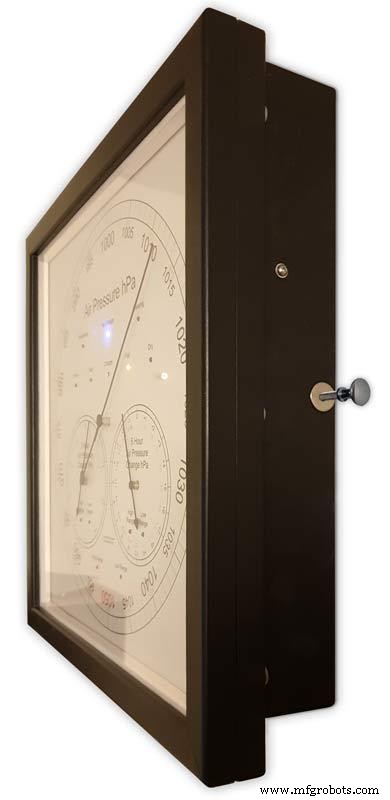
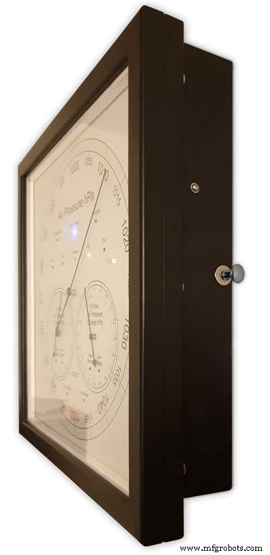
Pic.5 side view of the Barometer showing the back box.
Pic.6 shows my regulator clock case with original curved back box, hinged dial bezel and pegged dial surround.
Many of these clock cases were held in place by four wooden pegs. If your case is constructed like this add a pair of hinges to one side and use the remaining two pegs to lock the dial surround in place.
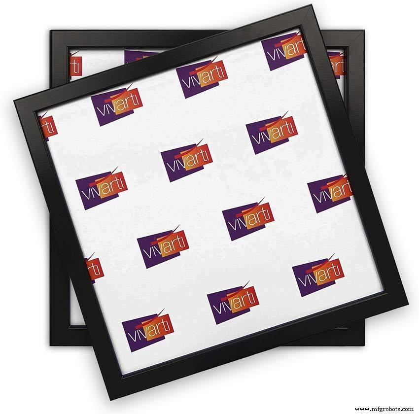
Step 18:Construction Modern Case
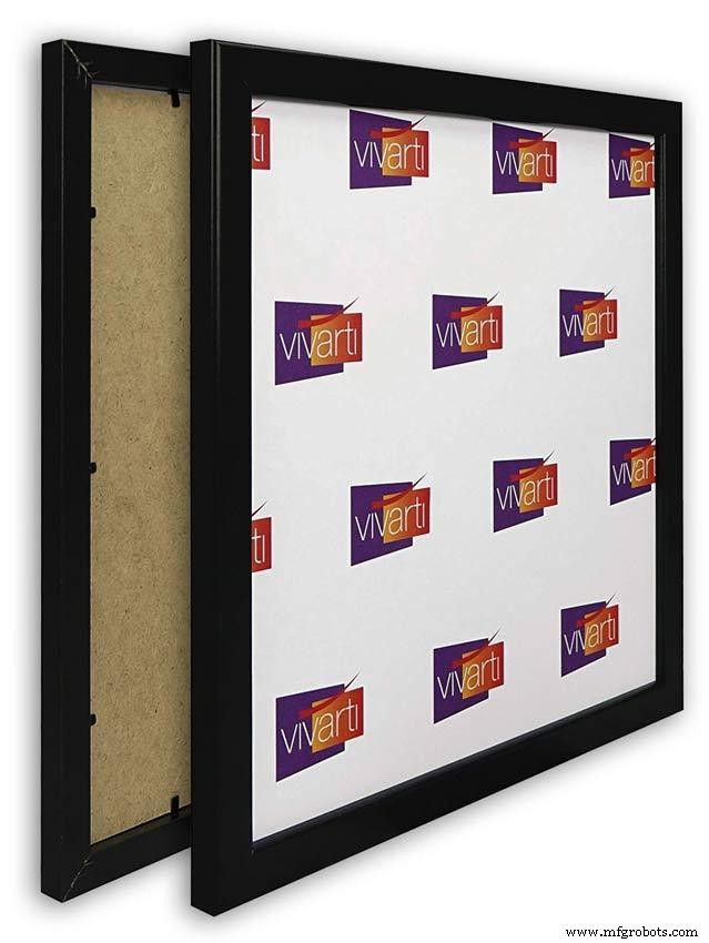


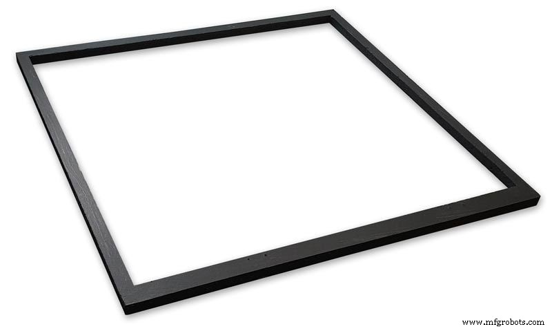
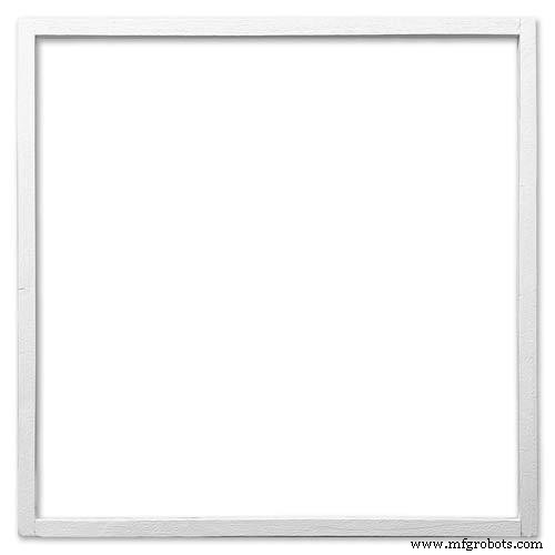
Picture Frame Version
I have used two identical picture frames mounted back to back. These frames are 30cm x 30cm approx. 12"x12" pic.1.
pic.2 Frames are joined back to back.
pic.3 This gives a double depth frame.
pic.4 Rear side view showing wired boards and modules.
pic.5 The dial viewed through the rear frame.
pic.6 Rear half of the frame with all wiring in place.
pic.7 The front of the dial now shows through the front half of the frame. Wooden bevels hide the space behind the front half of the frame.
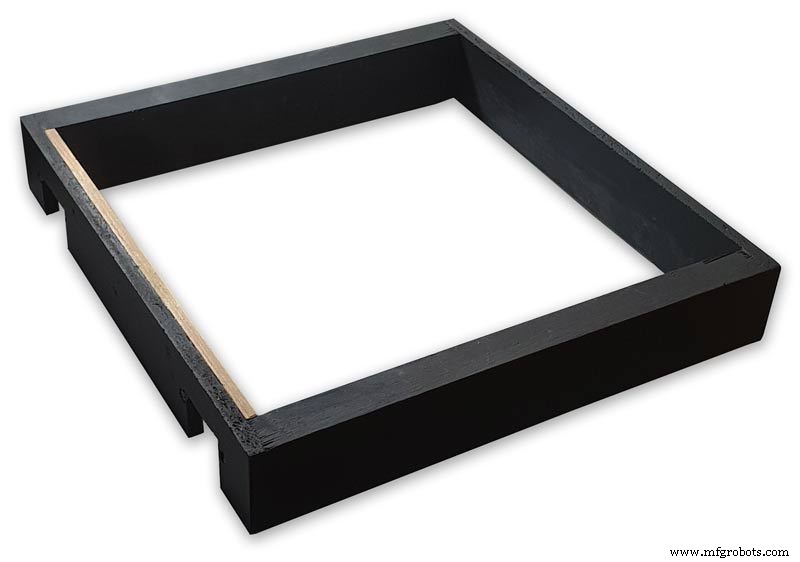
Step 19:Construction Modern Case Backbox
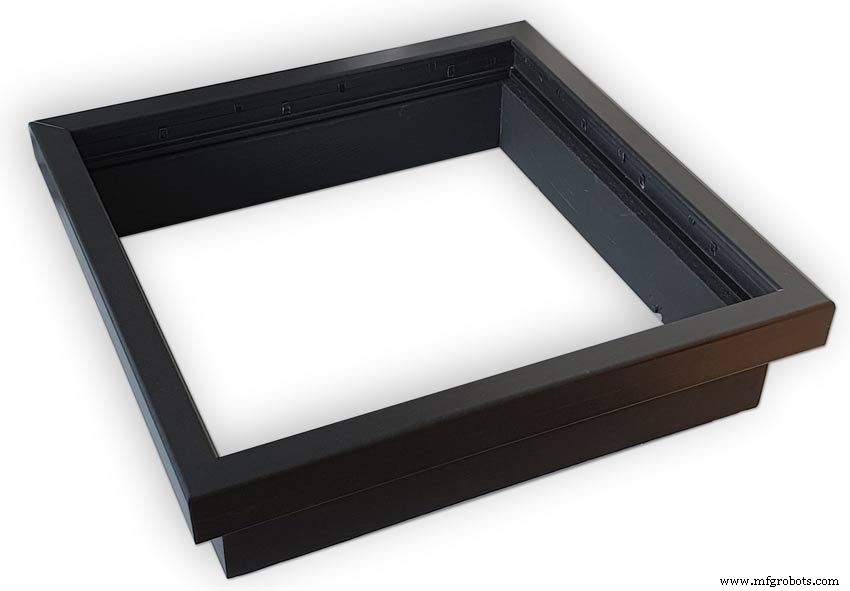
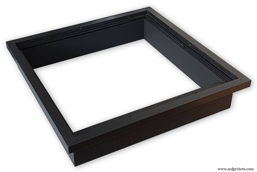


Back Box
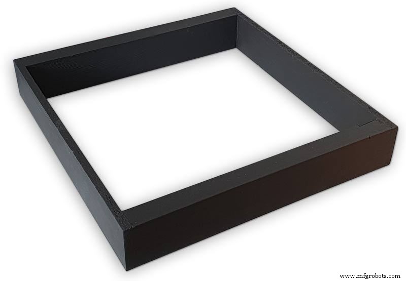
Pic.1 The barometer is housed in a back box that is smaller than the dial frame on all side apart from the top. The fram overlap helps hide the back box and adds a shadow effect to the case on the wall.
Pic.2 The back box is 50mm deep and is simply constructed of glued and screwed wood.
Pic.3 Rear view of back box in position behind rear dial frame showing the frame overlap.
Pic.4 The screw holes are filled then a coat of matt black is applied to the back box.
Pic.5 Back box with rear picture frame in place this holds the dial.Note the rear frame is placed upside down.
Pic.6 A spacer is cut the same size and depth as the recess of the picture frame.
Pic.7 The spacer is set under the dial.
Pic.8 This will raise the dial level with the top edge of the rear frame.
Pic.9 Back box with front picture frame in place on top of the rear frame.This frame holds the glass.
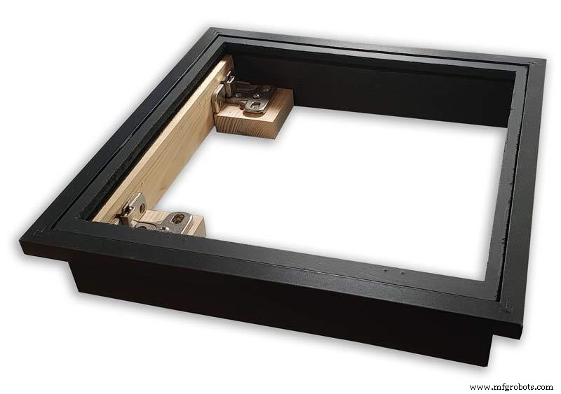
Step 20:Construction Modern Case Wall Mounting


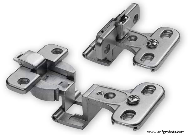
Mounting the Barometer
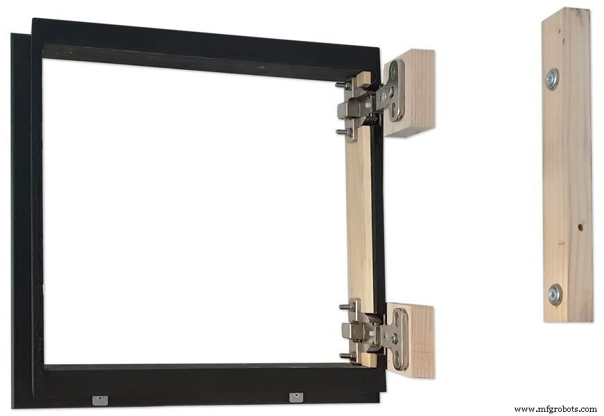
Pic.1 To allow access to the rear of the Barometer I have mounted it on a pair of GTV 270° inset hinges. The hinges are mounted on a block of wood fixed to the wall and allow the barometer to be swung out for access. The hinges also have a quick release function if the Barometer needs to be taken down for maintenance at any time. The hinge pivot is set back which also allows the top of the case to clear the wall when hinged out.
Pic.2 The hinges are mounted on wooden blocks screwed to the wall.
Pic.3 I have screwed and glued an extra piece of timber to the left hand side where the hinges will mount.This will add strength as all the weight of the clock will be on this side when the clock case is open. Two aluminium plates will cover the hinge holes.
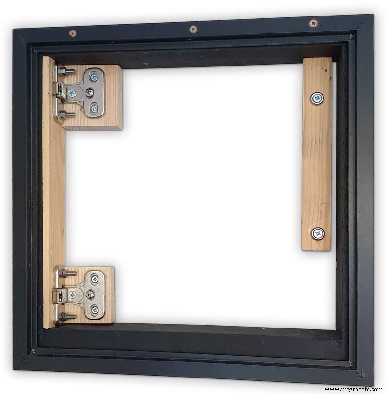
Pic.4 Hinge blocks in place. Note these are bolted through the case rather than screwed.
Pic.5 Back Box mounted on the wall. The fixing screws also hold the hinge to the wooden mounting blocks The wooden baton on the right is also fixed to the wall and supports the top right hand corner of the back box. It also serves as a fixing point for the wall mount locking pins that holds the back box shut against the wall.
Pic.6 The back box is shown open with the wooden mounting blocks and batons fixed to the wall. The hole in the front edge of the baton aligns with a hole in the side of the back box. A steel pin is inserted here to lock the barometer shut against the wall.
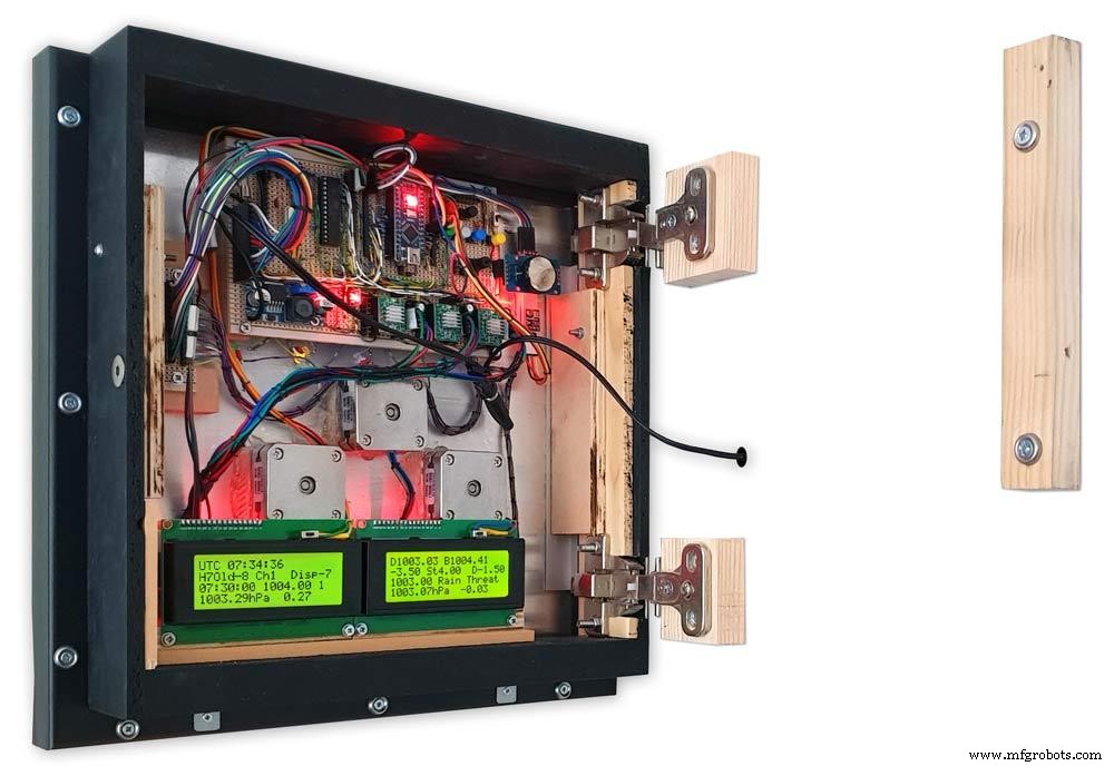
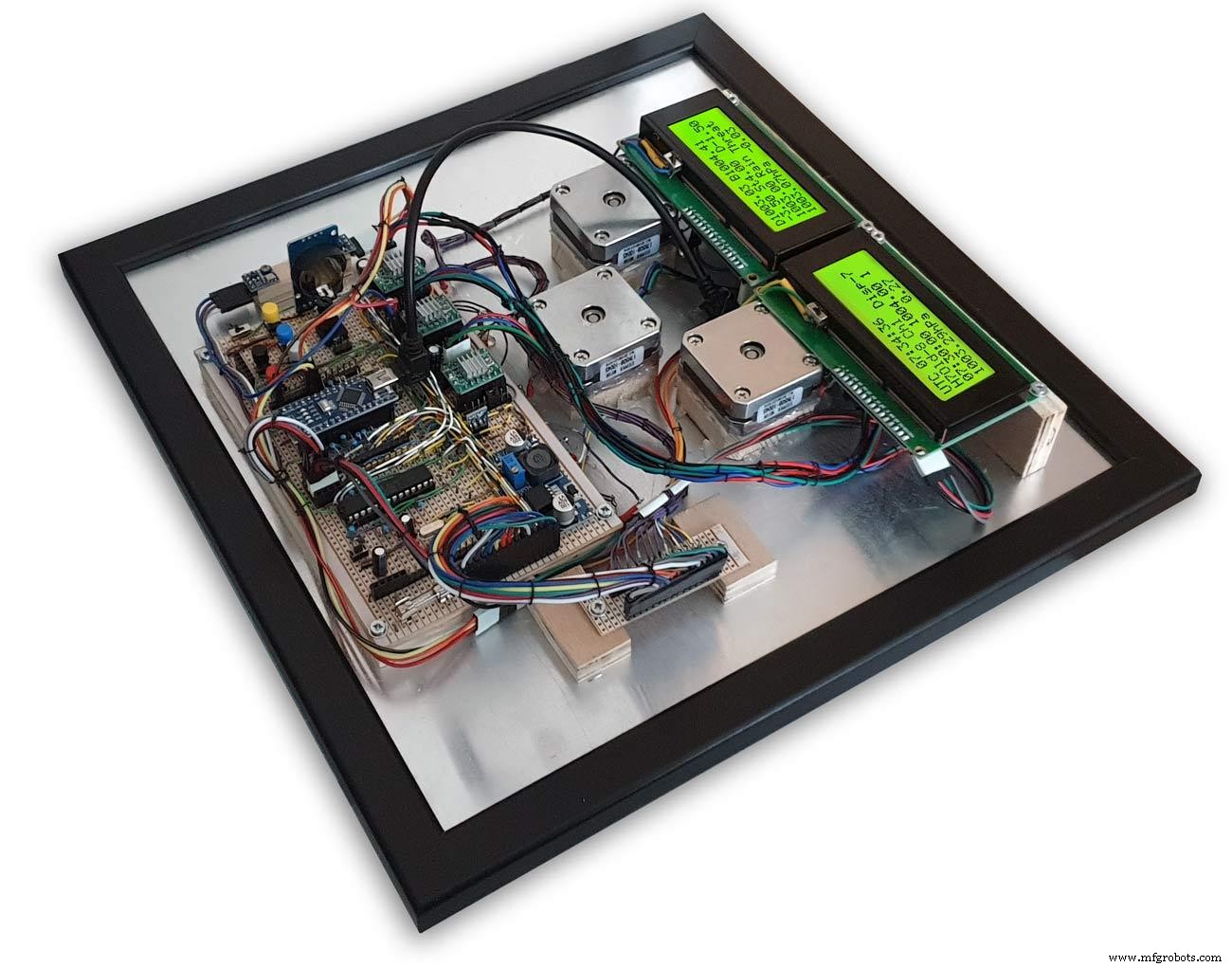
Pic.7 Back box open allowing access to the LCD displays and setting switches.
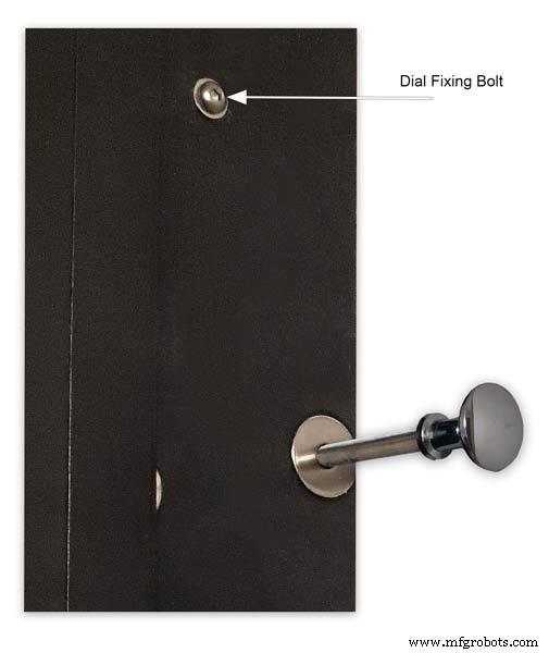
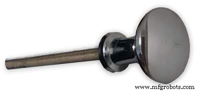
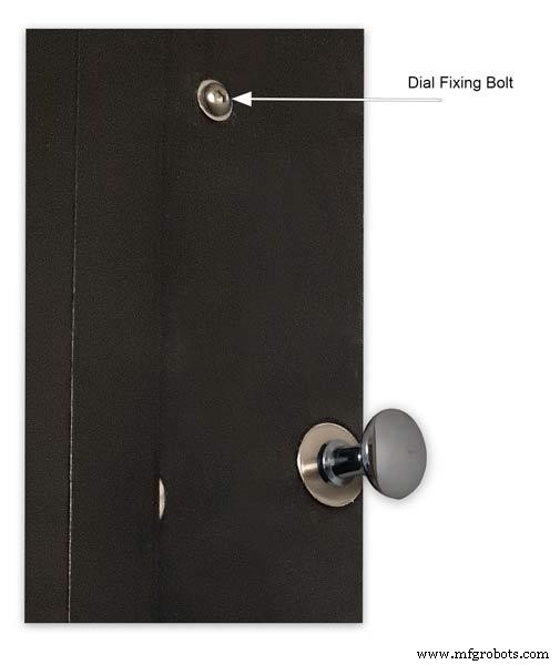
Pic.8 Steel Locking Pin This is a small cabinet knob with a length of treaded bar screwed into the thread.
Pic.9 &10 The locking pin when pushed fully in lock the barometer against the wall. When pulled out the barometer is able to swing out to allow access to the control switched and LCD displays.
Pic.11 Detail of Locking Pin and location of right side dial fixing bolt. I have glued a washer in place over the hole as an escutcheon plate.
Step 21:Construction Modern Case Dial Mounting

The dial and all the boards etc are removable for maintenance and is held to the backbox by 2 bolts.
Mounting the Dial in the Back Box
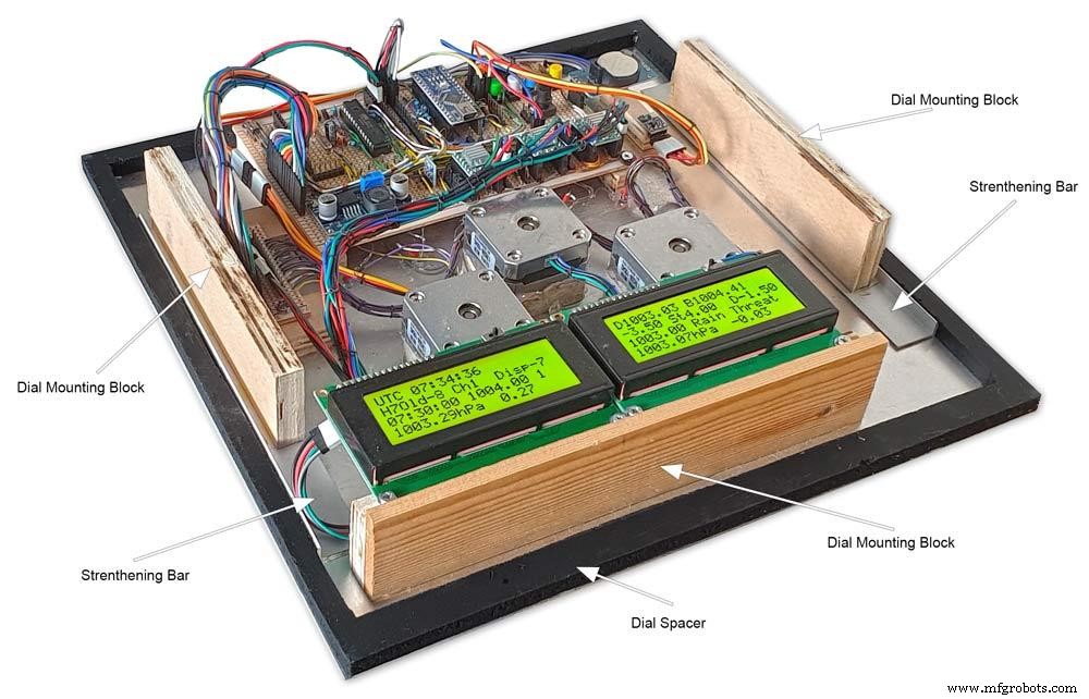
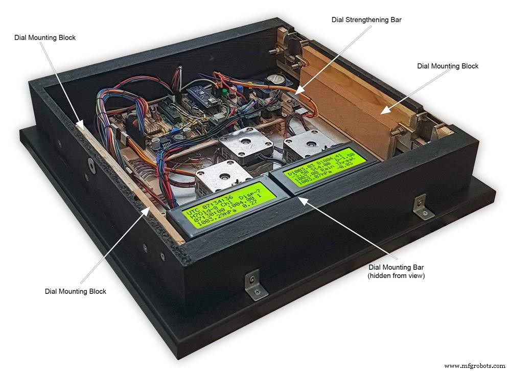
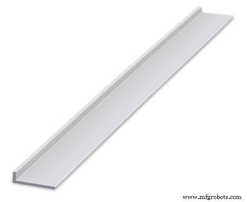
The dial holds the combined weight of all the stepper motors, boards and modules and is stiffened by impact gluing two strips of unequal aluminium angle to it's rear surface.Two blocks of wood are then glued to these bars and small screws then hold these wooden blocks through the side of the back box. A further thin strip of wood is glued to the dial below the LCD mounting block. This is not screwed to the case but sits on the back box to support the dial.
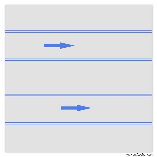
Pic.1 Strengthening bar of alluminium unequal angle.
Pic.2 Strengthening bar locations.
Pic.3 Glued wooden fixing/support blocks for dial fixing bolts left and right and glued dial support lower.
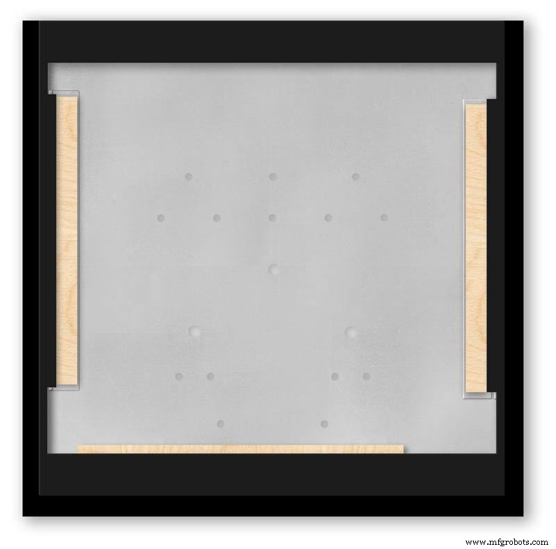
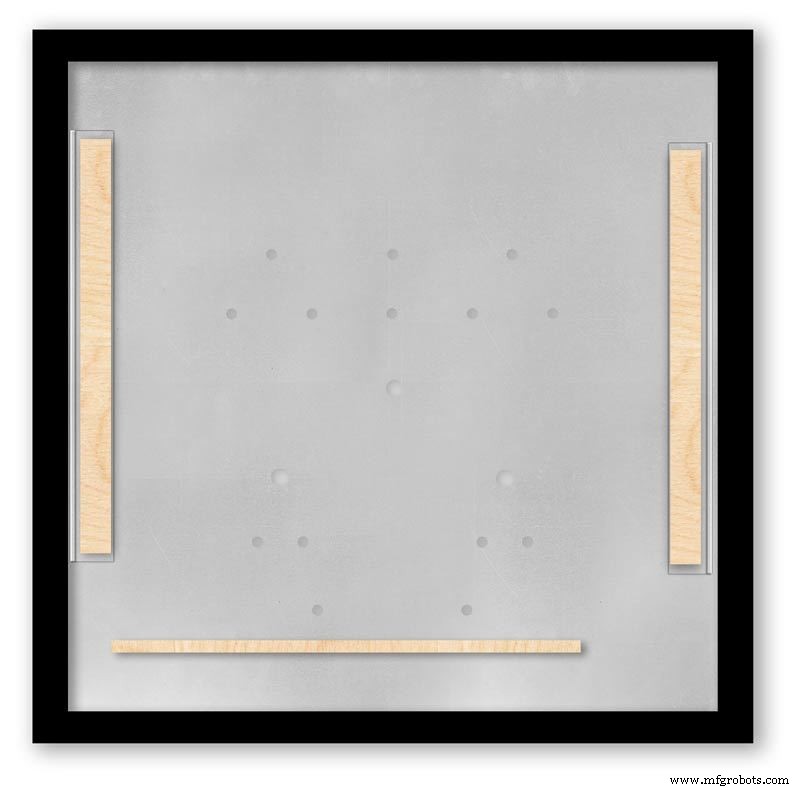
Pic.4 Shows contact/fixing points between the back box and dial. Back box in black with dial fixings/support in wood.
Pic.5 Rear view showing mounting block and bar locations.
Pic.6 Dial with Back Box Removed showing mounting blocks and strengthening bars glued to the rear of the dial.
The dial spacer allows the dial to sit flush with the top of the rear picture frame.
Pic.7 Right side of clock showing dial fixing bolt location.
Pic.8 A mount is constructed from 4 thin strips of wood and is placed in the recess of the front picture frame. This fills the gap between the picture frame and dial, holds the Perspex sheet in place and also adds a photo mount effect to the dial.
Pic.9 Mount in place behind the front picture frame.
Step 22:Contruction Dial
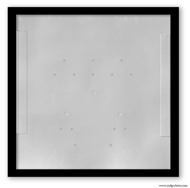
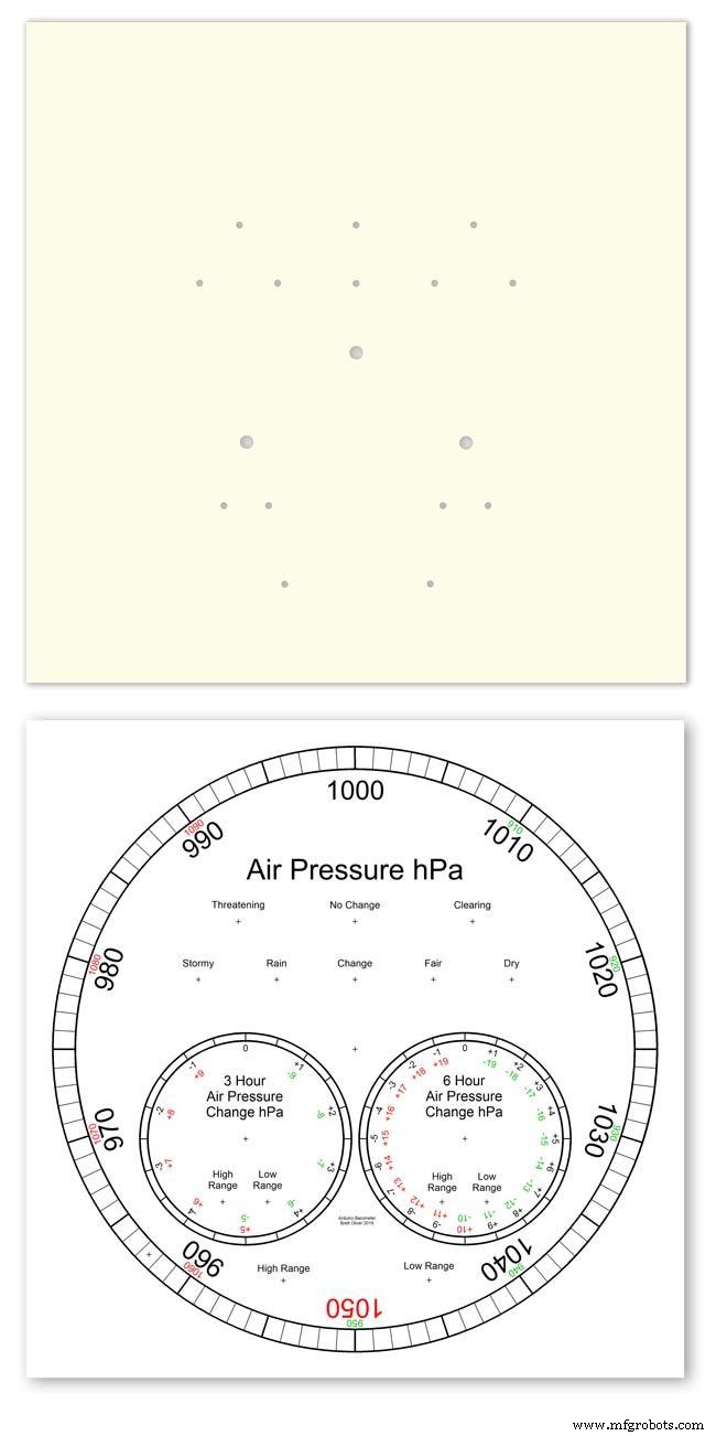
Pic.1 The dial is made from 1.5mm thick alluminium sheet and comes covered with a protective plastic film.
Pic.2 From your cad program print out the dial on A3 paper and include center marks for all the LED and stepper motor shaft holes.This will be your drill template.Lay the paper of the alluminium dial blank and tape the edges to stop it moving.Center punch all the holes through the paper.
Pic.3 Remove the paper template and drill out the holes 3mm for the LEDs and 3 larger holes for your stepper motor spindle.
Start with a small pilot hole and increase the drill size in 3 stages. If you are using a round dial mark it out on the projective film with a market pen and cut it out at this stage.
Pic.4 The protective plastic film can now be removed. Rub down the dial back and front to remove any burrs and to provide a key for the paint.
Pic.5 Spray a coat of acrylic primer and then your choice of top coat - I have used antique white.
I then give a final coat of matt clear acrylic. Leave to dry over night.
I have included a high res pic of the dial pic.6. Contact me if you need it in another format. My CAD format is TurboCad.
Step 23:Construction Dial Decal
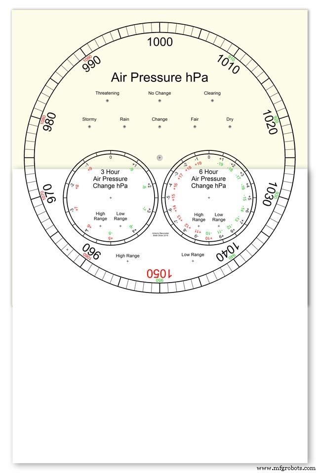
Apply the water slide decal transfer.
I use Water Slide Decal paper from BIGBITE Studio They have some good tutorials on their site. https://www.bigbitestudio.co.uk/tutorials/water-decal-tutorials/
Pic.1 Water slide decals are printed out on an inkjet printer soaked in water then slid into place. They give a very detailed print and once given a coat of varnish are tough.
Don't forget to order transparent transfers so the dial colour can be seen through the transfer.Follow the instructions with the pack as they do vary.
Pic.2 On my transfers I print out the dial on transfer paper let it dry and then cut it out to just under the size of the dial. I then give it a coat of acrylic varnish.
I set my printer as follows:Plain Paper, Photo &High Speed Off This stops my printer from over inking the paper When the varnish is dry the transfer is soaked in water until the transparent transfer comes away from the white backing sheet.
Pic.3 Move the soaked transfer over the dial.
Pic.4 Slide the transfer into position.
Pic.5 Gently pull the white backing paper backward while holding the transfer down.
Make sure the crosses line up with the center of all the holes.
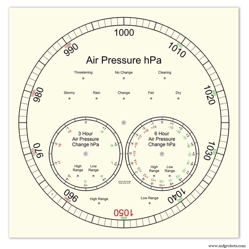
Pic.6 Get rid of any air bubbles.
Pic.7 Then leave it to dry before adding a coat of matt varnish.
After the coat of varnish break through the layer of transfer over the holes using the back of a drill bit jus smaller than the holes. Then give a final coat of varnish to seal the edges around the holes.
Step 24:Construction Hands
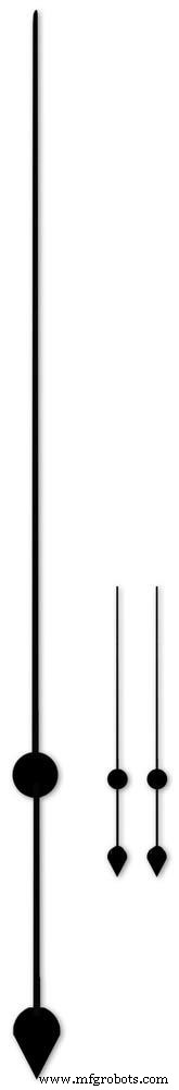
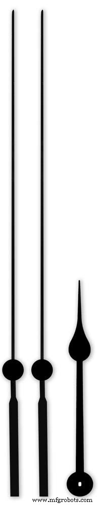

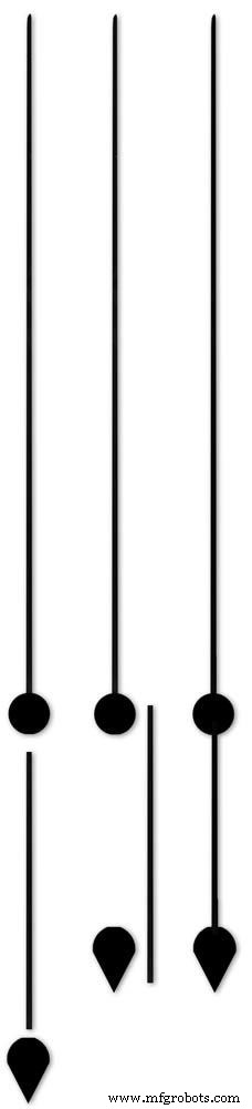


Hands are a very personnal choice and there are many diffent styles to choose from. The hardest part is finding hands that match each other. I found a perfect set of small hands but was unable to find a matching longhand for the main barometer. In the end I made my own from 3 donor hands.
All my hands were quartz second hands so I hand to file the mounting spindle off the back for mounting on the stepper motor spindle.
On some stepper motors the spindle can be drilled out to take the hand spindle but my spindles were too hard to drill.
Pic.1 my completed hands.
Pic.2 The long barometer hand was constructed from 3 different hands
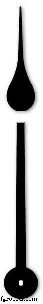
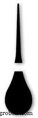
Pic.3 To get the lower spade balance part of the hand I used a spade hand.
Pic.4 First I cut off the top using sharp scissors.
Pic.5 The top was then trimmed by cutting the point off.
Pic.6 The remaining part was then filed away to match the shape of the 2 smaller hands.
Pic.7 The completed balance for the hand.
Pic.8 To make the front pointer and center I cut the end off one off my donor hands.
Pic.9 To make the rear balance shaft I cut a section out of the 3rd donor hand.
Pic.10 Left the 3 parts of the new hand. Middle shows the overlap of the balance shaft to allow for bonding. Right pic shows the balance shaft bonded with impact adhesive to the underside of the balance and center shaft.
To fix the hands to the stepper motor spindle I did not want to use impact adhesive as the hands are fragile and would be damaged if I hand to remove them. In the end I went for a tiny bit of Blu Tack on each hand. Blu Tack is putty like and is non setting but seems to hold very well!
Step 25:Construction Schematic
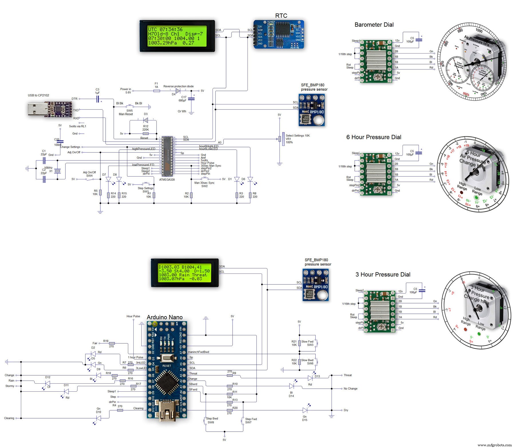
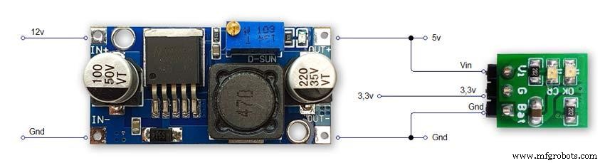
The main shematic is shown in Pic. 1 with the power supply in Pic.2.
You will also need a regulated plug in 12v supply adaptor of around 1amp.
Note I have fitted switches on the LCD displays to turn the backlight LEDs On and Off. This is optional but as the displays are not visible for 99.99% of the time it will save power.
Note larger schematics can be found on my web site here
Step 26:Construction Vero Board
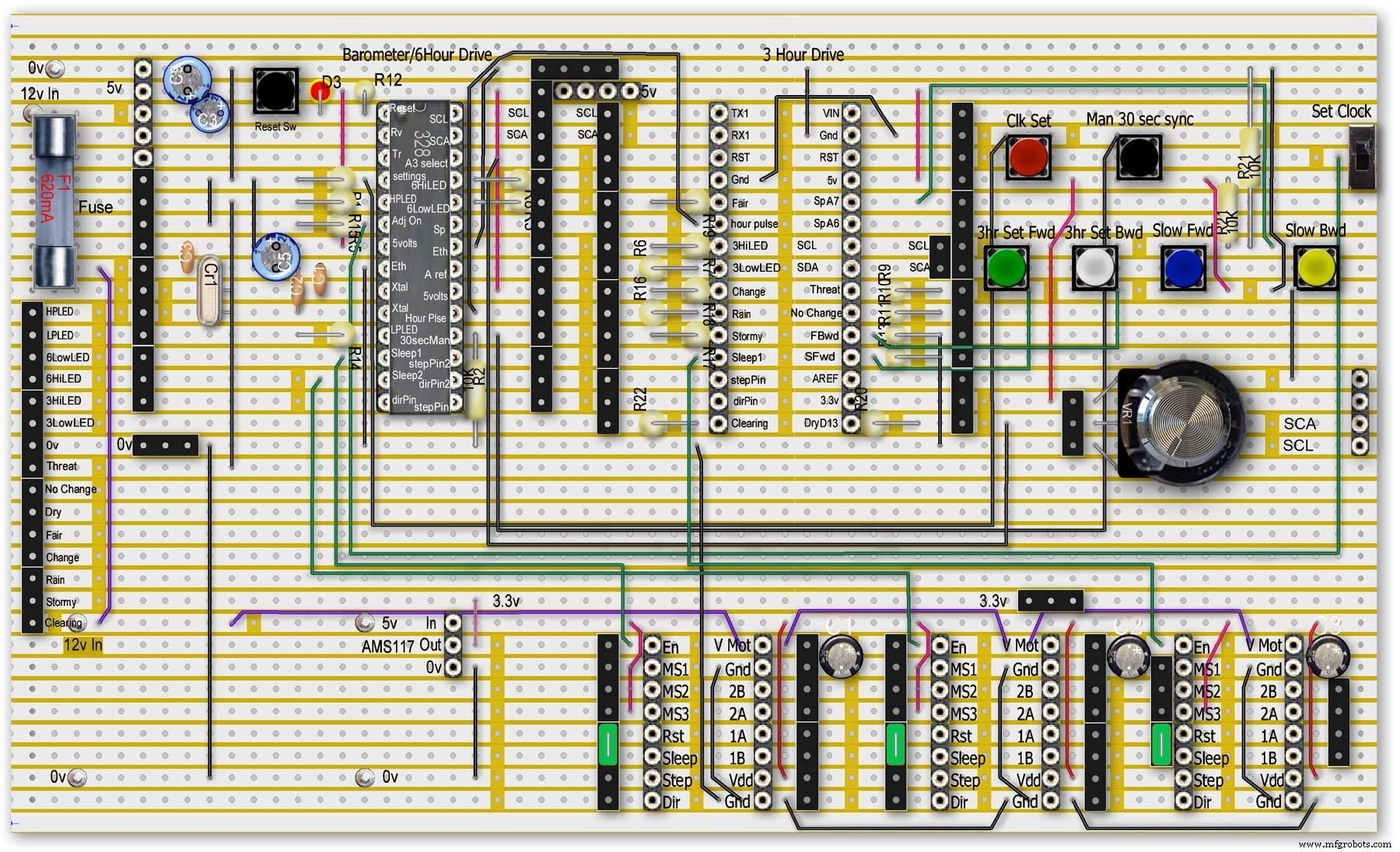
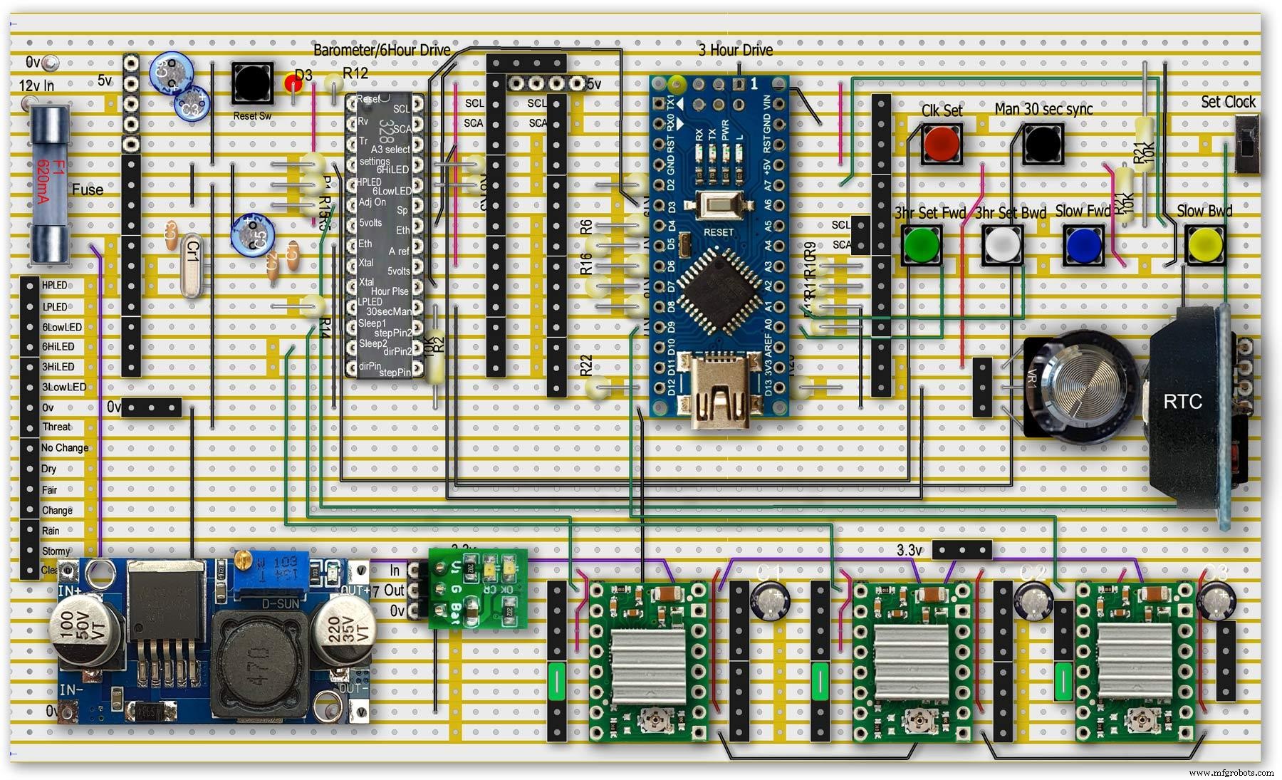
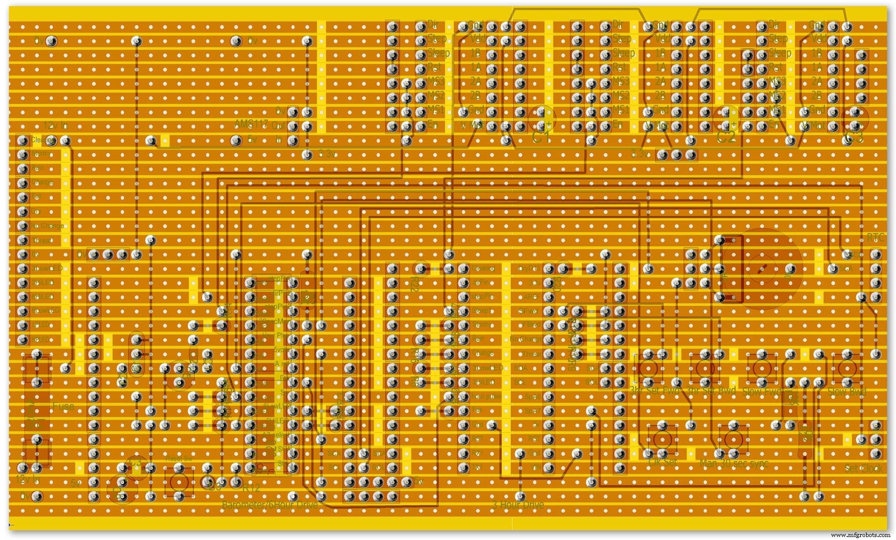
Vero Board Layouts
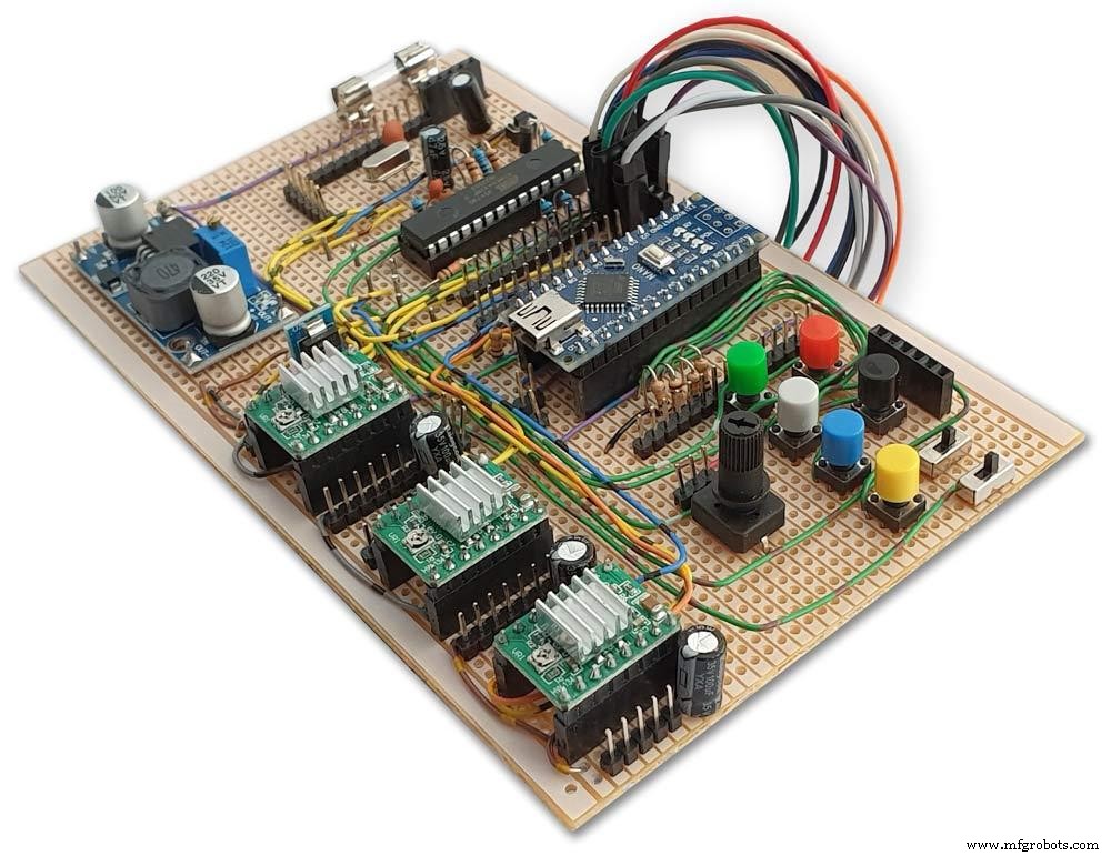
Pic.1 Vero Board with all modules removed.
Pic.2 Vero Board with modules in place.
Pic.3 Vero Board rear view (flipped down from top).
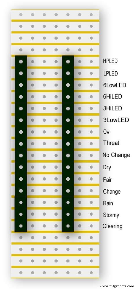
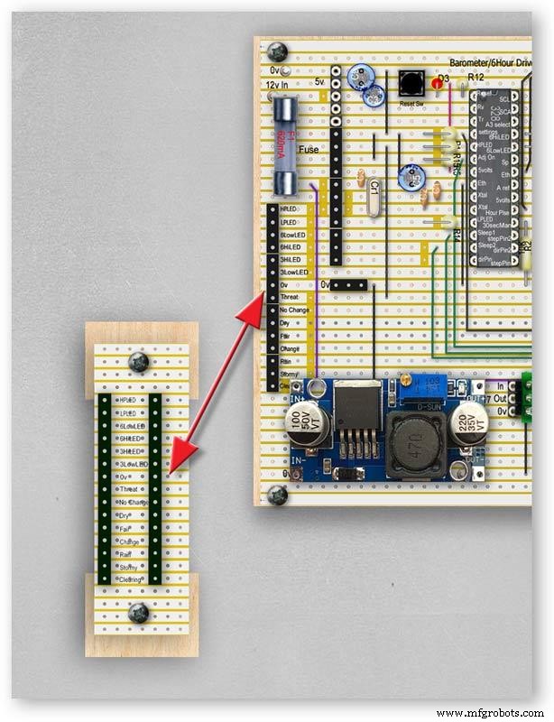
Pic.4 LED Vero Board
This board is used as a connection point for the dial LEDs. This allows the dial to be disconnected from the main board if required for maintenance.
Pic.5 The LED Vero Board connects to the main board with Dupont sockets and male Dupont cable
Pic.6 Vero Board wiring in progress.
Pic.7 Vero Boards and module location on the rear of the dial.
Step 27:Code
Code
There are 2 parts to the code 1 for the Main Barometer Code and 6 hour display and 1 for the 3 hour display and weather forecast.
Step 28:Time-Lapse Video
Time-Lapse Video showing rain radar and the Barometer predicting rain and a storm.
This is a 4K video so you should be able to see full details of the dial and forecast LEDs.
Código
- BarometerA4988_23.ino
- BarometerA4988_3hour__21.ino
BarometerA4988_23.inoArduino
Main file for Barometer and 6 hour display/* Example sketch to control a 28BYJ-48 stepper motor with ULN2003 driver board, AccelStepper and Arduino UNO:number of steps/revolutions. More info:https://www.makerguides.com v4 moved step 6 hour pressure step from void getpressure 1523 to main loop check every hour 365v5 remove unwamted step elementsv6 convert to diff display on 6 hr motorv8 modified hour change formula 1486v9 sleepv10 chnged high/low for EN control v11 chenge calc for hour change 1380v12 added calcCurrentDisp (); to calc current time from line 1384v13 removed 30 sec syncv14 air pressure extremes LEDsv15 add hour diff hour calc etc to row 1 when not on settingsv16 adding 16th stepsv17 errorv18 change min pulse to hour pulse on the hour + 1minv19 check enable and sleepsv20 added DAC to NANO so pins changed on 328 to match (analogue and digital swapped A6 D3 - deleted v20 also changed Low range hi range to both light above 19 or -19v21 same as 20 with serial print removedv23 notes added LCD display info added to startup */#include//SFE_BMP180 pressure sensor#include #include #include // ######## You will need to create an SFE_BMP180 object, here called "pressure":SFE_BMP180 pressure;#define ALTITUDE 118.0 // Altitude of Kenley Surrey in meters// also used to adjust/sync/calibrate to nearby weather station/3 hour display//#########//**********************// set the LCD address to 0x27 for a 20 chars 4 line display// Set the pins on the I2C chip us ed for LCD connections:// addr, en,rw,rs,d4,d5,d6,d7,bl,blpolLiquidCrystal_I2C lcd(0x27, 2, 1, 0, 4, 5, 6, 7, 3, POSITIVE); // Set the LCD I2C address#define DS3231_I2C_ADDRESS 0x68// Convert normal decimal numbers to binary coded decimalbyte decToBcd(byte val){ return( (val/10*16) + (val%10) );}// Convert binary coded decimal to normal decimal numbersbyte bcdToDec(byte val){ return( (val/16*10) + (val%16) );}// Include the AccelStepper library:#include // Define stepper motor connections and motor interface type. Motor interface type must be set to 1 when using a driver:#define dirPin 8#define stepPin 9#define dirPin2 10#define stepPin2 11#define motorInterfaceType 1// Create a new instance of the AccelStepper class:AccelStepper stepper =AccelStepper(motorInterfaceType, stepPin, dirPin);//barometer motorAccelStepper stepper2 =AccelStepper(motorInterfaceType, stepPin2, dirPin2);// 6 hour motorfloat seaPressure =0;float pressureNow =0;float pressurePrevious =0;float pressureDiff =0;int checkStop =0;int pressureRndDiff =0;int pressureRndNow =0;int pressureRndPrevious =0;int adjustOn =4; // allows adjustment of barometer// int test =0; // test mode 0 off 1 is onchar status; double T,P,a;//int h =0;//int m =0;//int j =0;int stepcount =0;int time =0;int resetmins =1;int secondNow =0;int secondPrevious=0;int minuteNow =0;int minutePrevious=0;int hourNow =0;int hourPrevious=0;int hourNow1=0;int hourPrevious1=0;int initial =0;int initial1 =0;int initial3 =0;int highPressureLED =3;int lowPressureLED =5;int hour6LowLED =15;int hour6HighLED =16;int manSync =12; // resets seconds to 30 secondsint changeSetting =2;int syncStop =0;int sync30Stop =0;int stepoffHour =0;int stepoffHourbkw =0;int stepoffMin =0;int stepoffMinbwd =0;int stepoffRTCminfwd =0;int stepoffRTCminbwd =0;int stepoffRTChourfwd =0;int stepoffRTChourbwd =0;int settingreadPin =A3; //Pin for sensing analogue value from potint settingVal =0; // Analogue value 0-1023int LCDstop =0; // stops settings on LCD display refreshing until they changeint hourPulse =13; //min pulse for seconds display was 14int adjustLock =0; // turns off adjust lockint hourcalc =0; // number from 0 to 7 representing the 8 hours of stored pressure readings int hourDiff =0; // used to check if 6hour previous motor should be stepped.int hourChange =0; // the amount of 6 hour to stepint currentDisplay =0; //current 6hour change readingint hour0 =1013; // you can set last 8 hours pressure here or leave at 0 and theint hour1 =1014; // readings will catch up over the next 8 hoursint hour2 =1015;int hour3 =1016;int hour4 =1016;int hour5 =1016;int hour6 =1012;int hour7 =1013;int sleep1 =6;int sleep2 =7;// check air pressure here https://www.meteoplug.com/cgi-bin/meteochart.cgi?draw=a3aeaaa1acbdf9f1fcfed4fedbc2c094c0d6d6d1d2c5edcebbfee9ffeff1fbf9//int Disp3hrIn =A3;//int Disp3hrVal =0;void setup() { pinMode(adjustOn, INPUT); pinMode(hourPulse, OUTPUT); pinMode(highPressureLED, OUTPUT); pinMode(lowPressureLED, OUTPUT); pinMode(hour6LowLED, OUTPUT); pinMode(hour6HighLED, OUTPUT); pinMode(manSync, INPUT); pinMode(sleep1, OUTPUT); pinMode(sleep2, OUTPUT); pinMode(settingreadPin, INPUT); // Set the maximum steps per second:stepper.setMaxSpeed(1000); stepper2.setMaxSpeed(1000); lcd.begin(20,4); // initialize the lcd for 20 chars 4 lines, turn on backlight lcd.backlight(); // backlight on not needed as man controlled lcd.setCursor(0,0); //Start at character 0 on line 0 lcd.print("Barometer A988"); //@@@@@@@@@@@@@@@@@@@@@@@@@@@@@@@@@@@@@@@@@@@@@@@@@@@@@@@@@@@@@@@@@@@@@@@@@@@@@@@@@@@@@@@@@@@@@@@@@@@@@@@@@@@@@@@@@@@@@@@@@@@@@@@@ lcd.setCursor(0,1); //Start at character 0 on line 1 lcd.print(" Version 23"); //@@@@@@@@@@@@@@@@@@@@@@@@@@@@@@@@@@@@@@@@@@@@@@@@@@@@@@@@@@@@@@@@@@@@@@@@@@@@@@@@@@@@@@@@@@@@@@@@@@@@@@@@@@@@@@@@@@@@@@@@@@@@@@@@ { Wire.begin(); Serial.begin (9600); // set the initial time here:// DS3231 seconds, minutes, hours, day, date, month, year // setDS3231time(10,42,9,5,18,12,19);//delay(2000);lcd.clear();}Serial.println("REBOOT");// serial removed // Initialize the sensor (it is important to get calibration values stored on the device). if (pressure.begin()) Serial.println("BMP180 init success");// serial removed else { // Oops, something went wrong, this is usually a connection problem, // see the comments at the top of this sketch for the proper connections. Serial.println("BMP180 init fail\n\n");// serial removed while(1); // Pause forever. } //LED TestdigitalWrite(hour6HighLED, HIGH);delay (500);digitalWrite(hour6HighLED, LOW);digitalWrite(hour6LowLED, HIGH);delay (500);digitalWrite(hour6LowLED, LOW);digitalWrite(highPressureLED, HIGH);delay (500);digitalWrite(highPressureLED, LOW);digitalWrite(lowPressureLED, HIGH);delay (500);digitalWrite(lowPressureLED, LOW);delay (500);lcd.clear();getPressure ();// gets all pressure readings// Disp readings on startup so hands can be set lcd.setCursor(0,1); lcd.print (""); lcd.setCursor (0,1); lcd.print("H"); lcd.print(hourcalc); lcd.setCursor(2,1); lcd.print (""); lcd.setCursor(2,1); lcd.print("Old"); lcd.print(currentDisplay); lcd.setCursor(13,1); lcd.print (""); lcd.setCursor(13,1); lcd.print("Disp"); lcd.print(hourDiff); //disable motors on startupdigitalWrite(sleep1, HIGH);digitalWrite(sleep2, HIGH);stepper.disableOutputs();stepper2.disableOutputs();// test =1; // test set to 0 off 1 on}void loop() { if( digitalRead(adjustOn) ==HIGH || adjustLock ==1)// only alow settings when change settings switch is ON{ //digitalWrite(sleep1, LOW);//enable on //digitalWrite(sleep2, LOW);//enable on only enable outputs for 2 mins Settings(); //set what function the setiing switches have adjustLock =1; //hold on adjustment if( digitalRead(adjustOn) ==LOW){//digitalWrite(sleep1, HIGH);//disable on//digitalWrite(sleep2, HIGH);//enable on only enable outputs for 2 minsadjustLock =0; //hold on adjustment } }// only allow settings change when setting switch is on // displayTime(); // display the real-time clock data on the Serial Monitor, byte second, minute, hour, dayOfWeek, dayOfMonth, month, year; // retrieve data from DS3231 readDS3231time(&second, &minute, &hour, &dayOfWeek, &dayOfMonth, &month, &year);//@@@@@@@@@@@@@@@@@@@@@@@@@@@@@@@@@@@@@@@@@@@@@@@@@@@@@@@@@@@@@@@@@@@@@@@@@@@@@@@@@@@@@@@@@@@@@@@@@@@@@@@@@@@@@@@@@ //enable air pressure readings if (minute ==9 || minute ==19 || minute ==29 || minute ==39 || minute ==49 || minute ==59 &&second ==59) { checkStop =0;// resets checkstop to allow air pressure readings every 10 mins }//check air pressure every 10 mins if (checkStop ==0) { if ( minute ==0 || minute ==10 || minute ==20 || minute ==30 || minute ==40 || minute ==50 ) { //digitalWrite(sleep1, LOW);//enable on -only enable outputs for 1 min // only sleep1 needs activation getPressure ();// gets all pressure readings checkStop =1;// stops multiple readings of air pressure }// else //digitalWrite(sleep1, HIGH);//enable off // Serial.print("Sleep 1 HIGH (off) "); // Serial.println(hourChange); } //@@@@@@@@@@@@@@@@@@@@@@@@@@@@@@@@@@@@@@@@@@@@@@@@@@@@@@@@@@@@@@@@@@@@@@@@@@@@@@@@@@@@@@@@@@@@@@@@@@@@@@@@@@@@@@@@if(digitalRead(manSync)==HIGH)// resets seconds to 30{ setDS3231time(30, minute, hour, dayOfWeek, dayOfMonth, month, year); //Set seconds to 30 on RTC } // counts seconds secondNow =second; if(secondNow!=secondPrevious || initial) { lcd.setCursor(0,0); lcd.print("UTC "); if(hour<10) { lcd.print(0); } lcd.print(hour); lcd.print(":"); if(minute<10) { lcd.print(0); } lcd.print(minute); lcd.print(":"); if(second<10) { lcd.print(0); } lcd.print(second); lcd.print (""); // Serial.print("-1*0 ");// Serial.println(-1*0); initial =0; secondPrevious =secondNow; } // count minutes minuteNow =minute; if(minuteNow!=minutePrevious || initial) //settingVal <690 stops clock motors operating when setting RTC { initial =0; minutePrevious =minuteNow; // digitalWrite(minPulse,HIGH);//1 min pulse for seconds display sync syncStop =0;// clock will not sync again untill a new minute has started. // digitalWrite(minPulse,LOW);//1 min pulse for seconds display sync } // counts hours + 1min for hourPulse at 15 seconds past the hour this allows barometer and 6 hour dial to step first if ( minute ==0 &&second ==15) // send hour pulse 15 seconds past the hour to 3 hour circuit allows other motors to stop { digitalWrite(hourPulse,HIGH); digitalWrite(highPressureLED,HIGH); // Serial.println("hourPulse Hi "); } else if (minute !=1 || second !=0) { digitalWrite(hourPulse,LOW);digitalWrite(highPressureLED,LOW); }// counts hours hourNow =hour; if ((minute ==59 &&second> 50) || (minute ==0 &&second <10) )// allows change on the hour only {// digitalWrite(sleep2, LOW);// enable 6hr motor if(hourNow!=hourPrevious || initial) //settingVal <690 stops clock motors operating when setting RTC { initial =0; hourPrevious =hourNow;//print hour stores every hour // serial removed /* Serial.print("hour0 "); Serial.println(hour0); Serial.print("hour1 "); Serial.println(hour1); Serial.print("hour2 "); Serial.println(hour2); Serial.print("hour3 "); Serial.println(hour3); Serial.print("hour4 "); Serial.println(hour4); Serial.print("hour5 "); Serial.println(hour5); Serial.print("hour6 "); Serial.println(hour6); Serial.print("hour7 "); Serial.println(hour7); */ //##############################################################################//step 6 hour motorif (hourChange> 0 &&hourChange <40) // 6 hour motor will not step if diff> 10 { stephourFwd(); //Serial.print("Step 6 hour Forward ");// serial removed // Serial.println(hourChange);// serial removed hourChange =0; } else if (hourChange <0 &&hourChange> -40) // else if (hourDiff ==-1 || test ==1) { stephourBwd(); // Serial.print("Step 6 Hour Backward ");// serial removed // Serial.println(hourChange);// serial removed hourChange =0; } // hourChange =0; //############################################################################## } // digitalWrite(sleep2, HIGH);// disable 6hr motor// add LCD stop if(second==0) { // lcd.setCursor(0,1); //lcd.print(" "); lcd.setCursor (0,1); lcd.print (""); lcd.setCursor (0,1); lcd.print("H"); lcd.print(hourcalc); lcd.setCursor(2,1); lcd.print (""); lcd.setCursor(2,1); lcd.print("Old"); lcd.print(currentDisplay); lcd.setCursor(13,1); lcd.print (""); lcd.setCursor(13,1); lcd.print("Disp"); lcd.print(hourDiff); } } } // Set Clock/Motors###################################################################################################//gets advance retard settings from potvoid Settings(){ settingVal =analogRead(settingreadPin); // read the value from the pot if ( settingVal>=0 &&settingVal <85 ) { setMinsfwd(); } if ( settingVal>=85 &&settingVal <170 ) { setMinsbwd(); } if ( settingVal>=170 &&settingVal <255 ) { setMinsslowfwd(); } if ( settingVal>=255 &&settingVal <340 ) { setMinsslowbkd(); } if ( settingVal>=340 &&settingVal <425 ) { setHoursfwd(); } if ( settingVal>=425 &&settingVal <510 ) { setHoursbwd(); } if ( settingVal>=510 &&settingVal <595 ) { setHoursslowfwd(); } if ( settingVal>=595 &&settingVal <690 ) { setHourslowbkd(); } if ( settingVal>=690 &&settingVal <765 ) { setRTCfwdmin(); } if ( settingVal>=765 &&settingVal <850 ) { setRTCbwdmin(); } if ( settingVal>=850 &&settingVal <900 ) { setRTCfwd(); } if ( settingVal>=900 &&settingVal <970 ) { setRTCbwd(); }if ( settingVal>=970 &&settingVal <1025 ) { } if ( settingVal>=0 &&settingVal <85 &&LCDstop==0)// LCDstop prevents the LCD from freshing until another item is selected { lcd.setCursor(0,1); lcd.print (""); lcd.setCursor (0,1); lcd.print("Barometer Advance"); LCDstop=1; } if ( settingVal>=85 &&settingVal <170 &&LCDstop==1) { lcd.setCursor(0,1); lcd.print (""); lcd.setCursor (0,1); lcd.print("Barometer Retard"); LCDstop=0; } if ( settingVal>=170 &&settingVal <255 &&LCDstop==0 ) { lcd.setCursor(0,1); lcd.print (""); lcd.setCursor (0,1); lcd.print("Baro Inch Advance"); LCDstop=1; } if ( settingVal>=255 &&settingVal <340 &&LCDstop==1 ) { lcd.setCursor(0,1); lcd.print (""); lcd.setCursor (0,1); lcd.print("Baro Inch Retard"); LCDstop=0; } if ( settingVal>=340 &&settingVal <425 &&LCDstop==0 ) { lcd.setCursor(0,1); lcd.print (""); lcd.setCursor (0,1); lcd.print("6Hr Baro Advance"); LCDstop=1; } if ( settingVal>=425 &&settingVal <510 &&LCDstop==1 ) { lcd.setCursor(0,1); lcd.print (""); lcd.setCursor (0,1); lcd.print("6Hr Baro Retard"); LCDstop=0; } if ( settingVal>=510 &&settingVal <595 &&LCDstop==0 ) { lcd.setCursor(0,1); lcd.print (""); lcd.setCursor (0,1); lcd.print("6Hr Baro Inch Advn"); LCDstop=1; } if ( settingVal>=595 &&settingVal <690 &&LCDstop==1 ) { lcd.setCursor(0,1); lcd.print (""); lcd.setCursor (0,1); lcd.print("6Hr Baro Inch Retard"); LCDstop=0; } if ( settingVal>=690 &&settingVal <765 &&LCDstop==0) { lcd.setCursor(0,1); lcd.print (""); lcd.setCursor (0,1); lcd.print("RTC Min Advance"); LCDstop=1; } if ( settingVal>=765 &&settingVal <850 &&LCDstop==1 ) { lcd.setCursor(0,1); lcd.print (""); lcd.setCursor (0,1); lcd.print("RTC Min Retard"); LCDstop=0; } if ( settingVal>=850 &&settingVal <900 &&LCDstop==0 ) { lcd.setCursor(0,1); lcd.print (""); lcd.setCursor (0,1); lcd.print("RTC Hour Advance"); LCDstop=1; } if ( settingVal>=900 &&settingVal <970 &&LCDstop==1 ) { lcd.setCursor(0,1); lcd.print (""); lcd.setCursor (0,1); lcd.print("RTC Hour Retard"); LCDstop=0; } if ( settingVal>=970 &&settingVal <1025 &&LCDstop==0 ) { lcd.setCursor(0,1); lcd.print (""); lcd.setCursor (0,1); lcd.print("OFF"); LCDstop=1; } }// END of Loop// set RTC min forward 1 min per press ##################################################################################void setRTCfwdmin(){ if( digitalRead(changeSetting) ==HIGH &&stepoffRTCminfwd ==0 ) { byte second, minute, hour, dayOfWeek, dayOfMonth, month, year; // retrieve data from DS3231 readDS3231time(&second, &minute, &hour, &dayOfWeek, &dayOfMonth, &month, &year); minute =minute+1; if (minute ==60) { minute =0; } setDS3231time(second, minute, hour, dayOfWeek, dayOfMonth, month, year); //Set seconds to 30 on RTC stepoffRTCminfwd =1; } if( digitalRead(changeSetting) ==LOW ) { stepoffRTCminfwd =0; }}//##################################################################################// set RTC min backward 1 min per press ##################################################################################void setRTCbwdmin(){ if( digitalRead(changeSetting) ==HIGH &&stepoffRTCminbwd ==0 ) { byte second, minute, hour, dayOfWeek, dayOfMonth, month, year; // retrieve data from DS3231 readDS3231time(&second, &minute, &hour, &dayOfWeek, &dayOfMonth, &month, &year); minute =minute-1; if (minute <1) { minute =59; } setDS3231time(second, minute, hour, dayOfWeek, dayOfMonth, month, year); //Set seconds to 30 on RTC stepoffRTCminbwd =1; } if( digitalRead(changeSetting) ==LOW ) { stepoffRTCminbwd =0; }}//##################################################################################//###################################################################################################// set RTC hour forward 1 hour per press ##################################################################################void setRTCfwd(){ if( digitalRead(changeSetting) ==HIGH &&stepoffRTChourfwd ==0 ) { byte second, minute, hour, dayOfWeek, dayOfMonth, month, year; // retrieve data from DS3231 readDS3231time(&second, &minute, &hour, &dayOfWeek, &dayOfMonth, &month, &year); hour =hour+1; setDS3231time(second, minute, hour, dayOfWeek, dayOfMonth, month, year); //Set seconds to 30 on RTC stepoffRTChourfwd =1; } if( digitalRead(changeSetting) ==LOW ) { stepoffRTChourfwd =0; }}//##################################################################################// set RTC hour backward 1 hour per press ##################################################################################void setRTCbwd(){ if( digitalRead(changeSetting) ==HIGH &&stepoffRTChourbwd ==0 ) { byte second, minute, hour, dayOfWeek, dayOfMonth, month, year; // retrieve data from DS3231 readDS3231time(&second, &minute, &hour, &dayOfWeek, &dayOfMonth, &month, &year); hour =hour-1; setDS3231time(second, minute, hour, dayOfWeek, dayOfMonth, month, year); //Set seconds to 30 on RTC stepoffRTChourbwd =1; } if( digitalRead(changeSetting) ==LOW ) { stepoffRTChourbwd =0; }}//##################################################################################// set Minutes Motor forward 1 min per press ##################################################################################void setMinsfwd(){ //digitalWrite(sleep1, LOW); //stepper.enableOutputs();// step minutes 1 min per press if( digitalRead(changeSetting) ==HIGH &&stepoffMin ==0 ) { //Serial.println("Step Forward Man");// serial removed stepoffMin =1; stepminsFwd(); } if( digitalRead(changeSetting) ==LOW ) { stepoffMin =0; }//digitalWrite(sleep1, HIGH); //stepper.disableOutputs();}//##################################################################################// set Minutes Motor backward 1 min per press ##################################################################################void setMinsbwd(){ //digitalWrite(sleep1, LOW); // stepper.enableOutputs(); if( digitalRead(changeSetting) ==HIGH &&stepoffMinbwd ==0 ) { // Serial.println("Step Backward Man");// serial removed stepoffMinbwd =1; stepminsBwd(); } if( digitalRead(changeSetting) ==LOW ) { stepoffMinbwd =0; }//digitalWrite(sleep1, HIGH); // stepper.disableOutputs();}//##################################################################################// step minutes slow forward const press ##################################################################################void setMinsslowfwd(){ stepper.enableOutputs(); digitalWrite(sleep1, LOW); if( digitalRead(changeSetting) ==HIGH ) { // Serial.println("Step Baro Inch Forward Man");// serial removed stepper.setCurrentPosition(0); // Run the motor forward at 500 steps/second until the motor reaches 4096 steps (1 revolution):while (stepper.currentPosition() !=1) { //was 52 52x60 =3120 stepper.setSpeed(50); stepper.runSpeed(); } /* digitalWrite(motorPin1, LOW); digitalWrite(motorPin2, LOW); digitalWrite(motorPin3, LOW); digitalWrite(motorPin4, LOW);*/ } digitalWrite(sleep1, HIGH); stepper.disableOutputs();}//##################################################################################// step minutes slow backward const press ##################################################################################void setMinsslowbkd(){ stepper.enableOutputs(); digitalWrite(sleep1, LOW); if( digitalRead(changeSetting) ==HIGH ) { // Serial.println("Step Baro Inch Backward Man");// serial removed stepper.setCurrentPosition(0); // Run the motor forward at 500 steps/second until the motor reaches 4096 steps (1 revolution):while (stepper.currentPosition() !=-1) { //was 52 52x60 =3120 stepper.setSpeed(-50); stepper.runSpeed(); } /* digitalWrite(motorPin1, LOW); digitalWrite(motorPin2, LOW); digitalWrite(motorPin3, LOW); digitalWrite(motorPin4, LOW);*/ } digitalWrite(sleep1, HIGH); stepper.disableOutputs();}//##################################################################################// set Hour Motor forward 1 hour per press ##################################################################################void setHoursfwd(){ // stepper2.enableOutputs(); // digitalWrite(sleep2, LOW); // step hours 1 hour per press if( digitalRead(changeSetting) ==HIGH &&stepoffHour ==0 ) { // Serial.println("Step 6hr Forward Man");// serial removed stepoffHour =1; stephourmanFwd(); } // stepper2.disableOutputs(); // digitalWrite(sleep2, HIGH);if( digitalRead(changeSetting) ==LOW ) { stepoffHour =0; }...This file has been truncated, please download it to see its full contents.
BarometerA4988_3hour__21.inoArduino
File for 3 hour display and forecasting/* Example sketch to control a 28BYJ-48 stepper motor with ULN2003 driver board, AccelStepper and Arduino UNO:number of steps/revolutions. More info:https://www.makerguides.com v4 added presure extreme LEDsv5 add forcast LEDs and calcv6 sorted enable and sleep orderv7 remove adjust on and test replace it with Clearing and threatening LEDs PIN 12 and 13 v8 add dac driver-deletedv9 added LCDv10 added weather forecast usingLEDs v12 LEds test addedv13 add 1 dp point to 3 hour displayv14 void 1026 add slow set buttonsv18 voided v19last reading not included in number of stepsv20 change led test orderv20a serial.print removed indicated by // serial removedv21 as 20a identical to v20 that includes serial print*/#include//SFE_BMP180 pressure sensor#include #include // ######## You will need to create an SFE_BMP180 object, here called "pressure":SFE_BMP180 pressure;#define ALTITUDE 125.0 // Altitude of Kenley Surrey in meters//#########//**********************// set the LCD address to 0x27 for a 20 chars 4 line display// Set the pins on the I2C chip used for LCD connections:// addr, en,r w,rs,d4,d5,d6,d7,bl,blpolLiquidCrystal_I2C lcd(0x27, 2, 1, 0, 4, 5, 6, 7, 3, POSITIVE); // Set the LCD I2C address//#define DS3231_I2C_ADDRESS 0x68// Convert normal decimal numbers to binary coded decimalbyte decToBcd(byte val){ return( (val/10*16) + (val%10) );}// Convert binary coded decimal to normal decimal numbersbyte bcdToDec(byte val){ return( (val/16*10) + (val%16) );}// Include the AccelStepper library:#include // Define stepper motor connections and motor interface type. Motor interface type must be set to 1 when using a driver:#define dirPin 11#define stepPin 10#define motorInterfaceType 1// Create a new instance of the AccelStepper class:AccelStepper stepper =AccelStepper(motorInterfaceType, stepPin, dirPin);float seaPressure =0;float pressureNow =0;float pressurePrevious =0;float pressureDiff =0;int checkStop =0;//int pressureRndDiff =0;int pressureRndNow =0;int pressureRndPrevious =0;int adjustOn =12; // allows adjustment of barometer// int test =0; // test mode 0 off 1 is onchar status; double T,P,a;//int h =0;//int m =0;//int j =0;int stepcount =0;//int time =0;//int resetmins =1;//int secondNow =0;//int secondPrevious=0;//int minuteNow =0;//int minutePrevious=0;//int hourNow =0;//int hourPrevious=0;int initial =0;int initial1 =0;int initial3 =0;//int sync30 =3;//30sec sync on pin18//int syncLED =15;//int manSync =12;//int adjustOn =12;//int syncStop =0;//int sync30Stop =0;int stepoffHour =0;int stepoffHourbkw =0;int stepoffMin =0;int stepoffMinbwd =0;//int stepoffRTCminfwd =0;//int stepoffRTCminbwd =0;//int stepoffRTChourfwd =0;//int stepoffRTChourbwd =0;//int settingreadPin =A3; //Pin for sensing analogue value from pot//int settingVal =0; // Analogue value 0-1023int LCDstop =0; // stops settings on LCD display refreshing until they changeint hourPulse =3; //hour pulse from main Barometer Arduinoint adjustLock =0; // turns off adjust lockint hourcalc =0;float hourDiff =0.50; // used to check if 3hour previous motor should be stepped.float hourChange =0.00; // the amount of 3 hour to step float valueint hourStep =0; //the amount of 3 hour to stepint hourStepdigit1 =0; // gets the 1st digit from hourstepint hourStepdigit2 =0; // gets the 2nd digit from hourstepint stepTotal =0; // tptal amount of steps for 3 hour motorint hourChangeNeg =0;// if hour change is -ve this stores the value to chenge stepTotal laterfloat currentDisplay =0.50; //current 3hour change readingfloat hour0 =1036.00; // you can set last 3 hours pressure here or leave at 0 and thefloat hour1 =1036.00; // readings will catch up over the next 4 hoursfloat hour2 =1036.00;float hour3 =1036.00;float hour4 =1036.00;//check readings https://www.meteoplug.com/cgi-bin/meteochart.cgi?draw=a3aeaaa1acbdf9f1fcfed4fedbc2c094c0d6d6d1d2c5edcebbfee9ffeff1fbf9int sleep =9;int hourPulseOff =0;//int testinput =17;int testpulse =0;int hourPlus1min =0;int stepFwd1 =14;int manstepFwd1 =0;int maninchFwdBwd =A7;int stepBwd1 =15;int manstepBwd1 =0;int hour3LowLED =5;// Green low range LEDint hour3HighLED =4;//Red high range LEDint ledStormy =8;int ledRain =7;int ledChange =6;int ledFair =2;int ledDry =13;int ledClear =12;int ledThreat =17;int ledNoChange =16;//Testint n =0;int n1 =0;int n2 =0;void setup() { pinMode(ledStormy, OUTPUT); pinMode(ledRain, OUTPUT); pinMode(ledChange, OUTPUT); pinMode(ledFair, OUTPUT); pinMode(ledDry, OUTPUT); pinMode(ledClear, OUTPUT); pinMode(ledThreat, OUTPUT); pinMode(ledNoChange, OUTPUT); pinMode(stepFwd1, INPUT); pinMode(stepBwd1, INPUT); // pinMode(adjustOn, INPUT); pinMode(hourPulse, INPUT); pinMode(hour3LowLED, OUTPUT); pinMode(hour3HighLED, OUTPUT); pinMode(sleep, OUTPUT); // pinMode(settingreadPin, INPUT); // Set the maximum steps per second:stepper.setMaxSpeed(1000); lcd.begin(20,4); // initialize the lcd for 20 chars 4 lines, turn on backlight lcd.backlight(); // backlight on not needed as controlled by 7 MAX2719 lcd.setCursor(0,0); //Start at character 0 on line 0 lcd.print("Barometer A988 3 Hr"); //@@@@@@@@@@@@@@@@@@@@@@@@@@@@@@@@@@@@@@@@@@@@@@@@@@@@@@@@@@@@@@@@@@@@@@@@@@@@@@@@@@@@@@@@@@@@@@@@@@@@@@@@@@@@@@@@@@@@@@@@@@@@@@@@ lcd.setCursor(0,1); //Start at character 0 on line 0 lcd.print(" Version 20"); //@@@@@@@@@@@@@@@@@@@@@@@@@@@@@@@@@@@@@@@@@@@@@@@@@@@@@@@@@@@@@@@@@@@@@@@@@@@@@@@@@@@@@@@@@@@@@@@@@@@@@@@@@@@@@@@@@@@@@@@@@@@@@@@@ { // Wire.begin(); Serial.begin (9600); delay(2000);lcd.setCursor(0,2); //Start at character 0 on line 0 lcd.print("##### LED TEST #####"); //@@@@@@@@}//#############################################################Serial.println("REBOOT v08");//############################################################ // Initialize the sensor (it is important to get calibration values stored on the device). if (pressure.begin()) Serial.println("BMP180 init success"); else { // Oops, something went wrong, this is usually a connection problem, // see the comments at the top of this sketch for the proper connections. Serial.println("BMP180 init fail\n\n"); while(1); // Pause forever. }// test =1; // test set to 0 off 1 on//LED Testdelay (2000);digitalWrite(ledThreat, HIGH);delay (500);digitalWrite(ledThreat, LOW);digitalWrite(ledNoChange, HIGH);delay (500);digitalWrite(ledNoChange, LOW);digitalWrite(ledClear, HIGH);delay (500);digitalWrite(ledClear, LOW);digitalWrite(ledStormy, HIGH);delay (500);digitalWrite(ledStormy, LOW);digitalWrite(ledRain, HIGH);delay (500);digitalWrite(ledRain, LOW);digitalWrite(ledChange, HIGH);delay (500);digitalWrite(ledChange, LOW);digitalWrite(ledFair, HIGH);delay (500);digitalWrite(ledFair, LOW);digitalWrite(ledDry, HIGH);delay (500);digitalWrite(ledDry, LOW);digitalWrite(hour3HighLED, HIGH);delay (500);digitalWrite(hour3HighLED, LOW);digitalWrite(hour3LowLED, HIGH);delay (500);digitalWrite(hour3LowLED, LOW); lcd.clear (); getPressure ();// gets all pressure readings showLCD(); // load display to LCD getForecast(); //get forcast and set LEDs for weather //disable motors on startupdigitalWrite(sleep, HIGH);stepper.disableOutputs(); }void loop() { hourPlus1min =(digitalRead(hourPulse));//checks for pulse at 1min past the hour from the barometer if (hourPlus1min ==HIGH &&hourPulseOff ==0 || initial1 ) { initial1 =0; hourcalc++; if (hourcalc> 4) { hourcalc =0; } //Serial.print("hourcalc ");// serial removed // Serial.println(hourcalc);// serial removed getPressure ();// gets all pressure readings getForecast(); //get forcast and set LEDs for weather showLCD(); // load display to LCD hourPulseOff =1; //turns off } else if (hourPlus1min ==LOW) { hourPulseOff =0; } adjustLock =0; //hold on adjustment// Step forward/back man~~~~~~~~~~~~~~~~~~~~~~~~~~~~~~~ // step hours 1 hour per press manstepFwd1 =digitalRead(stepFwd1); if( manstepFwd1 ==HIGH &&stepoffHour ==0 ) { stepoffHour =1; stephourmanFwd(); } manstepFwd1 =digitalRead(stepFwd1);if( manstepFwd1 ==LOW ) { stepoffHour =0; } // step hours 1 hour per press manstepBwd1 =digitalRead(stepBwd1); if( manstepBwd1 ==HIGH &&stepoffHour ==0 ) { stepoffHour =1; stephourmanBwd(); } manstepBwd1 =digitalRead(stepBwd1); if( manstepBwd1 ==LOW) { stepoffHour =0; } //~~~~~~~~~~~~~~~~~~~~~~~~~~~~~~~~~~~~~~~~~~~~~~~~ //Inch 3hr forward/backwardsmaninchFwdBwd=analogRead(A7);if (maninchFwdBwd>800 ){// Serial.print(" maninchFwdBwd=");// serial removed // Serial.println(maninchFwdBwd);// serial removed maninchFwd(); } else if (maninchFwdBwd <200) { // Serial.print(" maninchFwdBwd=");// serial removed// Serial.println(maninchFwdBwd);// serial removed maninchBwd(); } //##############################################################################//step 3 hour motorif (hourChange> 0 &&hourChange <20) // 3 hour motor will not step if diff> 40 { stephourFwd(); // Serial.print("Step 3 hour Forward ");// serial removed // Serial.println(hourChange);// serial removed hourChange =0; } else if(hourChange <0 &&hourChange> -20) { stephourBwd(); // Serial.print("Step 3 Hour Backward ");// serial removed // Serial.println(hourChange);// serial removed hourChange =0; } //############################################################################## } //##################################################################################// set Hour Motor backward 1 hour per press ##################################################################################void setHoursbwd(){ // digitalWrite(sleep, LOW);// stepper.enableOutputs(); // step hours 1 hour per press if( digitalRead(adjustOn) ==HIGH &&stepoffHourbkw ==0 ) { // Serial.println("Step 3hr Backward Man"); stepoffHourbkw =1; stephourmanBwd(); }// stepper.disableOutputs();// digitalWrite(sleep, HIGH);if( digitalRead(adjustOn) ==LOW ) { stepoffHourbkw =0; }// End step hours 1 hour per press}//##################################################################################// step hours slow forward const press ##################################################################################void maninchFwd(){ stepper.enableOutputs(); digitalWrite(sleep, LOW); if( digitalRead(adjustOn) ==HIGH ) { // Serial.println("Step 3hr Inch Forward Man");// serial removed stepper.setCurrentPosition(0); // Run the motor forward at 500 steps/second until the motor reaches 8 steps (1 revolution):while (stepper.currentPosition() !=1) { //was 52 52x60 =3120 stepper.setSpeed(10); stepper.runSpeed(); } } digitalWrite(sleep, HIGH);stepper.disableOutputs();}//##################################################################################// step hours slow backward const press ##################################################################################void maninchBwd(){ stepper.enableOutputs(); digitalWrite(sleep, LOW); if( digitalRead(adjustOn) ==HIGH ) { // Serial.println("Step 3hr Inch backward Man");// serial removed stepper.setCurrentPosition(0); // Run the motor forward at 500 steps/second until the motor reaches 8 steps (1 revolution):while (stepper.currentPosition() !=-1) { //was 52 52x60 =3120 stepper.setSpeed(-10); stepper.runSpeed(); } } digitalWrite(sleep, HIGH);stepper.disableOutputs();}//################################################################################## //Hour Motor #####################################################################################################void stephourFwd() // steps hour hand forward 1 hour{ stepper.enableOutputs(); // Serial.println("Step 3 hrs forward auto");// serial removed digitalWrite(sleep, LOW); stepper.setCurrentPosition(0); // Run the motor forward at 500 steps/second until the motor reaches 4096 steps (1 revolution):while (stepper.currentPosition() !=hourChange*160) { //hourDiff gives the nuber of steps to take stepper.setSpeed(400); stepper.runSpeed(); } digitalWrite(sleep, HIGH); stepper.disableOutputs(); }//###############################################################################################################//Hour Motor #####################################################################################################void stephourBwd() // steps hour hand backward 1 hour{ stepper.enableOutputs(); //Serial.println("Step 3hrs backward auto");// serial removed digitalWrite(sleep, LOW); stepper.setCurrentPosition(0);while ( stepper.currentPosition() !=hourChange*160) { stepper.setSpeed(-400); stepper.runSpeed(); }digitalWrite(sleep, HIGH); stepper.disableOutputs(); }//###############################################################################################################//Hour Motor Man Step forward#####################################################################################################void stephourmanFwd() // steps hour hand forward 1 hour{ stepper.enableOutputs(); digitalWrite(sleep, LOW); //Serial.println("Step 3hr forward man");// serial removed stepper.setCurrentPosition(0); // Run the motor forward at 500 steps/second until the motor reaches 4096 steps (1 revolution):while ( stepper.currentPosition() !=160) { stepper.setSpeed(400); stepper.runSpeed(); } digitalWrite(sleep, HIGH); stepper.disableOutputs(); }//###############################################################################################################//Hour Motor Man Step back ward #####################################################################################################void stephourmanBwd() // steps hour hand backward 1 hour{ stepper.enableOutputs(); digitalWrite(sleep, LOW); // Serial.println("Step 3hr backward man");// serial removed stepper.setCurrentPosition(0);while ( stepper.currentPosition() !=-160) { stepper.setSpeed(-400); stepper.runSpeed(); }digitalWrite(sleep, HIGH); stepper.disableOutputs(); }//###############################################################################################################void getPressure ()//get all pressure readings checked every 10 mins eg 0 10 20 etc{ if (checkStop ==0){ // If you want sea-level-compensated pressure, as used in weather reports, // you will need to know the altitude at which your measurements are taken. // We're using a constant called ALTITUDE in this sketch:// Serial.println(); // Serial.print("provided altitude:"); // Serial.print(ALTITUDE,0);// Serial.print(" meters, "); // Serial.print(ALTITUDE*3.28084,0);// Serial.println(" feet"); // If you want to measure altitude, and not pressure, you will instead need // to provide a known baseline pressure. This is shown at the end of the sketch. // You must first get a temperature measurement to perform a pressure reading. // Start a temperature measurement:// If request is successful, the number of ms to wait is returned. // If request is unsuccessful, 0 is returned. status =pressure.startTemperature(); if (status !=0) { // Wait for the measurement to complete:delay(status); // Retrieve the completed temperature measurement:// Note that the measurement is stored in the variable T. // Function returns 1 if successful, 0 if failure. status =pressure.getTemperature(T); if (status !=0) { // Print out the measurement:// Serial.print("temperature:"); // Serial.print(T,2); // Serial.print(" deg C, "); // Serial.print((9.0/5.0)*T+32.0,2); // Serial.println(" deg F"); // Start a pressure measurement:// The parameter is the oversampling setting, from 0 to 3 (highest res, longest wait). // If request is successful, the number of ms to wait is returned. // If request is unsuccessful, 0 is returned. status =pressure.startPressure(3); if (status !=0) { // Wait for the measurement to complete:delay(status); // Retrieve the completed pressure measurement:// Note that the measurement is stored in the variable P. // Note also that the function requires the previous temperature measurement (T). // (If temperature is stable, you can do one temperature measurement for a number of pressure measurements.) // Function returns 1 if successful, 0 if failure. status =pressure.getPressure(P,T); if (status !=0) { // Print out the measurement:// Serial.print("absolute pressure:"); // Serial.print(P,2); // Serial.print(" mb, "); // Serial.print(P*0.0295333727,2); // Serial.println(" inHg"); // The pressure sensor returns abolute pressure, which varies with altitude. // To remove the effects of altitude, use the sealevel function and your current altitude. // This number is commonly used in weather reports. // Parameters:P =absolute pressure in mb, ALTITUDE =current altitude in m. // Result:p0 =sea-level compensated pressure in mb seaPressure =pressure.sealevel(P,ALTITUDE); // we're at 160 meters (Kenley, Surrey UK) // serial removed /* Serial.print("relative (sea-level) pressure:"); Serial.print(seaPressure,2); Serial.print(" mb, "); Serial.print(seaPressure*0.0295333727,2); Serial.println(" inHg"); */ // On the other hand, if you want to determine your altitude from the pressure reading, // use the altitude function along with a baseline pressure (sea-level or other). // Parameters:P =absolute pressure in mb, p0 =baseline pressure in mb. // Result:a =altitude in m. a =pressure.altitude(P,seaPressure); // Serial.print("computed altitude:"); // Serial.print(a,0); // Serial.print(" meters, "); // Serial.print(a*3.28084,0); // Serial.println(" feet"); } else Serial.println("error retrieving pressure measurement\n"); } else Serial.println("error starting pressure measurement\n"); } else Serial.println("error retrieving temperature measurement\n"); } else Serial.println("error starting temperature measurement\n");}//Serial.print("hourscalc "); // Serial.println(hourcalc);if (hourcalc ==0){ hour0 =seaPressure;//was rnd sea pressure currentDisplay =hourDiff; // the last display reading becomes the old reading called currentDisplay hourDiff =hour0 - hour3; // this is the air pressure difference from now to the reading 3 hours ago and wil be displayed onthe 3 hour dial calcCurrentDisp (); // calculates 3 hour Air pressure display }else if (hourcalc ==1){ hour1 =seaPressure; currentDisplay =hourDiff; hourDiff =hour1 - hour4; calcCurrentDisp (); }else if (hourcalc ==2 ){ hour2 =seaPressure; currentDisplay =hourDiff;hourDiff =hour2 - hour0; calcCurrentDisp (); }else if (hourcalc ==3 ){ hour3 =seaPressure; currentDisplay =hourDiff; hourDiff =hour3 - hour1; calcCurrentDisp (); }else if (hourcalc ==4 ){ hour4 =seaPressure; currentDisplay =hourDiff; hourDiff =hour4 - hour2; calcCurrentDisp (); }//show 3 hour pressure scale hi/low LEDsif(hourDiff> 9 || hourDiff <-9) // if 3 hour pressure is outside of extended range both hi and low range leds light{digitalWrite( hour3HighLED, HIGH); digitalWrite( hour3LowLED, HIGH);}else if(hourDiff>=4.80) { digitalWrite( hour3HighLED, HIGH); digitalWrite( hour3LowLED, LOW); } else if (hourDiff <=-4.80) { digitalWrite( hour3LowLED, HIGH); digitalWrite( hour3HighLED, LOW); } else if ( hourDiff <4.80 &&hourDiff>-4.80 ) { digitalWrite( hour3LowLED, LOW); digitalWrite( hour3HighLED, LOW); } // Serial.print("currentDisplay (old) ");// serial removed // Serial.println(currentDisplay);// serial removed// Serial.print("3 hour display to show ");// serial removed// Serial.println(hourDiff);// serial removed//Serial.print("RND seaPressure ");//Serial.println(round(seaPressure));//get pressure change and show change over 1 hour on LCD bottom row pressureNow =seaPressure; if ( pressureNow !=pressurePrevious || initial ) { initial =0; pressureDiff =pressureNow - pressurePrevious; //Print pressure and diff on LCD lcd.setCursor(0,3); if (pressurePrevious ==0.00) { pressurePrevious =pressureNow;// shows previous pressure at startup } if(pressurePrevious<1000) { lcd.print(0); } lcd.print(pressurePrevious);// shows previous pressure until 1hPa change lcd.print("hPa "); // pressurePrevious =pressureNow; lcd.setCursor (12,3); lcd.print(" ");//blank section lcd.setCursor(12,3); lcd.print(pressureDiff); // show rounded pressure reading on display updayes every hour lcd.setCursor(0,2); lcd.print (""); // show rounded pressure on lcd lcd.setCursor(0,2); if(pressureNow<1000) { lcd.print(0); } lcd.print(round(pressureNow)); } pressureRndPrevious =pressureRndNow; pressurePrevious =pressureNow;//resets pressure change//################################################################################# } //####################################################################// show forecast on LEDs/* Predicting the Weather With the BarometerMore specifically, a barometer with readings in hPa can be interpreted in this manner:If the reading is over 1022 hPa Rising or steady pressure means continued fair weather.Slowly falling pressure means fair weather.Rapidly falling pressure means cloudy and warmer conditions.If it falls between 1009–1022 hPa Rising or steady pressure means present conditions will continue.Slowly falling pressure means little change in the weather.Rapidly falling pressure means that rain is likely, or snow if it is cold enough.If the reading is under (1009 hPaRising or steady pressure indicates clearing and cooler weather.Slowly falling pressure indicates rainRapidly falling pressure indicates a storm is coming.Rising or Fallin g slowlyPressure change of 0.1 to 1 mb in the preceding three hoursRising or FallingPressure change of 1 to 3 mb in the preceding three hoursRising or Falling quicklyPressure change of 3 to 6 mb in the preceding three hoursRising or Falling very rapidlyPressure change of more than 6.0 mb in the preceding three hours */void getForecast(){ //reading is under (1009 hPa //Rising or steady pressure indicates clearing and cooler weather if(seaPressure <1009.00 &&hourDiff>=0 ) { ClearforecastLED();// clear all forecast LEDs before changing digitalWrite( ledChange, HIGH); digitalWrite( ledClear, HIGH); lcd.setCursor(8,2); lcd.print (""); lcd.setCursor(8,2); lcd.print("Chg Clearing"); } //reading is under (1009 hPa //Slowly falling pressure indicates rain else if(seaPressure <1009.00 &&hourDiff <0 &&hourDiff>=-1.5 ) { ClearforecastLED(); digitalWrite( ledRain, HIGH); digitalWrite( ledThreat, HIGH); lcd.setCursor(8,2); lcd.print(" "); lcd.setCursor(8,2); lcd.print("Rain Threat"); } //reading is under (1009 hPa //Rapidly falling pressure indicates a storm is coming. else if(seaPressure <1009.00 &&hourDiff <-1.5 ) { ClearforecastLED(); digitalWrite( ledStormy, HIGH); digitalWrite( ledThreat, HIGH); lcd.setCursor(8,2); lcd.print(" "); lcd.setCursor(8,2); lcd.print("Storm Threat"); } //1009–1022 hPa //Rising or steady pressure means present conditions will continue. //Slowly falling pressure means little change in the weather. else if(seaPressure>=1009.00 &&seaPressure <=1022.00 &&hourDiff>=-1.5 &&hourDiff <=1.5 ) { ClearforecastLED(); digitalWrite( ledNoChange, HIGH); digitalWrite( ledFair, HIGH); lcd.setCursor(8,2); lcd.print(" "); lcd.setCursor(8 ,2); lcd.print("Fair No Chge"); }//1009–1022 hPa //Rising rapidly //Clearing else if(seaPressure>=1009.00 &&seaPressure <=1022.00 &&hourDiff>1.5 )...This file has been truncated, please download it to see its full contents.
Esquemas

Proceso de manufactura