


La evolución del prensado de mangueras hidráulicas
Desde sus humildes comienzos operados a mano hasta las máquinas habilitadas para IoT, las prensas hidráulicas para mangueras son una pieza fundamental del equipo que cualquier usuario de energía hidráulica debe comprender.
Sería difícil encontrar a alguien en esta industria hidráulica que nunca haya fabricado un conjunto de manguera hidráulica. Los técnicos hidráulicos se ganan la vida fabricando tuberías de varias configuraciones. Aún así, incluso los diseñadores e ingenieros probablemente se ensuciaron las manos en la escuela como parte de una clase de introducción sobre el tema. La mayoría de las veces, los profesionales de la energía de fluidos se iniciaron en el taller de mangueras local antes de pasar a las filas de un distribuidor o fabricante. No obstante, muchos de los que ahora están leyendo esto están familiarizados con las técnicas utilizadas para engarzar una manguera hidráulica.
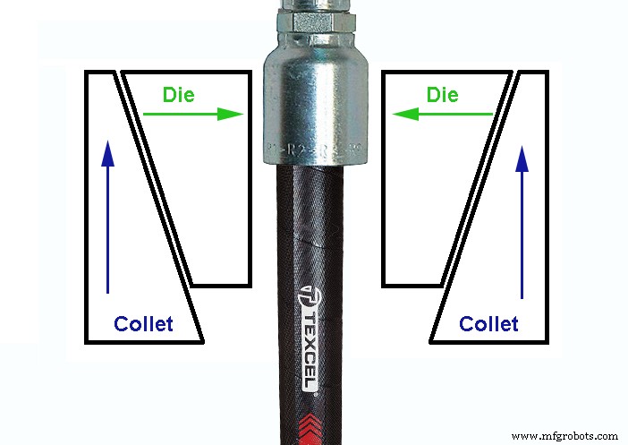
Como era de esperar, el equipo de prensado de mangueras se originó con un comienzo humilde. Cualquier máquina capaz de ejercer una fuerza radial sobre el diámetro exterior de una férula de extremo de manguera haría el truco. Al principio de sus diseños, los ingenieros aprovecharon la disposición del cono y el asiento para los troqueles de prensado, un sistema que sigue siendo muy popular en la actualidad. El collar actúa como un asiento, y cuando empuja contra la forma de cono de los dados, los dados son forzados hacia adentro (ver figura 1).
Los fanfarrones de manos fueron lo primero
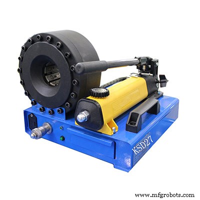
Siempre que pueda empujar las matrices o las boquillas para lograr el vector de fuerza hacia adentro deseado, la forma cónica ofrece una ventaja mecánica para ayudar en la compresión de la férula del extremo de la manguera. La primera tecnología de crimpado de mangueras utilizaba el buen poder humano a la antigua para lograr el resultado deseado. Las primeras prensas de estampado funcionaban girando una manija en T grande, girando un tornillo de máquina a través de una cabeza fija, forzando el extremo contra el juego de troqueles de dos piezas.
En el caso de estas prensas manuales portátiles, los troqueles se mueven hacia abajo contra el collarín fijo y, a medida que los troqueles se mueven hacia abajo, también se comprimen hacia adentro. El técnico debe sostener el extremo de la manguera con cuidado con una mano mientras gira el mango con la mano opuesta. Una vez que los troqueles sujetan el accesorio con la suficiente firmeza, el técnico usa ambas manos para forzar la engarzadora hasta que toque fondo. Es esencial usar solo las matrices y los extremos de manguera correspondientes específicos para la aplicación.
Estas unidades portátiles operadas a mano no ofrecen la misma tecnología de diámetro de engaste automático que los nuevos sistemas que emplean micrómetros. Simplemente sujete la unidad hasta que las dos piezas lleguen al fondo y espere que logre su especificación de crimpado. La medición del engarce aún ofrece al técnico la confirmación de que el engarce se encuentra dentro de las especificaciones, pero necesita contar con su experiencia con el dispositivo para producir resultados consistentemente precisos. También debo mencionar que muchos técnicos todavía usan máquinas portátiles de estampado manual en la actualidad.
El sistema hidráulico añade velocidad y potencia
Hay algo satisfactorio en una máquina prensadora de mangueras accionada hidráulicamente. Una máquina totalmente eléctrica simplemente no se siente bien, como una hamburguesa sin carne o un Mazda Miata con transmisión automática. La adición de densidad de potencia hidráulica a la máquina prensadora ofreció al técnico un método más rápido y potente para prensar los extremos de las mangueras. El collar de la prensa hidráulica es esencialmente un cilindro hidráulico anular. En algunos casos, dos cilindros empujan dicho anillo anular. La fuerza creada por los cilindros empuja las pinzas o las matrices, obligando a estas últimas a cerrarse sobre el extremo de la manguera con mucha fuerza.
La principal dificultad con las primeras máquinas prensadoras era su falta de versatilidad. Los troqueles utilizados eran específicos para el extremo de la manguera, lo que animaba al técnico o al taller de mangueras a utilizar únicamente productos del mismo fabricante. If a shop wished to use various hoses and ends, a method to vary the crimp diameter had to offer variability in the crimp OD while still offering accuracy down to the thousandths of an inch.
Rather than limit the technician to fixed diameter dies, instead offering dies capable of a range of internal diameters brought in that variability to allow multiple types and sizes of assemblies. Instead of an exact diameter of, say, 0.733 in., the dies now offer a range from 0.700-0.788 in. for example. What could previously only crimp a ½ in. hose end may now crimp 1- and 2-wire hose from 3/8 to ½ in.
Dies designed for variable diameter applications present the challenge of accuracy, of course. The dies can only bottom out on their smallest setting, which may not always be helpful for any hose or fitting the shop offers. Crimp machine designers had to engineer a method to stop the crimping procedure at the desired size accurately. No technician is skilled enough to stop the hydraulic pump by feel with 0.002 in. accuracy or better.
Accurate and repeatable
Installing an adjustable limit switch offered the most accurate and repeatable solution to the variable die set. An adjustable micrometer attached to the limit switch allows the technician to set the depth of the limit switch to within a thousandth of an inch or less. When the crimp actuator contacts the limit switch, the pump stops automatically. So long as the micrometer has been calibrated, the crimp diameter is both accurate and precise for every single operation.
Hydraulic crimpers using the micrometer were the standard for decades, offering precise control to make hose assembly quick and straightforward. Much of the advancement, until recently, has been improvements to the practicality of the machine. Dual-stage hydraulic pumps provided the technician with rapid die travel until the clamping pressure was met, where the stages switched to the smaller, high-pressure pump for maximum force.
Convenient die storage systems to offer rapid and precise tooling changes also sped up the pace for busy hose shops changing between sizes. A die-set loader offered the technician ease of pulling dies from their holder where they’re inserted into the crimper before being clamped in place. The tidy die storage and replacement systems so widespread today beat the old habit of sifting through drawers or bins where every die of every size mingled with no organization.
Electronic control
Just as the rest of the industry moved towards electronic control, so too did the hose crimping machine. Some technicians found the traditional dial-micrometer hard to read and adjust, and often found itself out of calibration. Linear position sensors replaced the limit switches, and then the adjustment option went digital. A small LCD screen shows the crimp setting, which increased accuracy and reduced the chance for error. The precision of the linear transducer all but guarantees perfect, repeatable crimps.
Some hydraulic hose assembly equipment manufacturers have produced semi-automated hose assembly stations. One such machine requires only that the operator load the parts into the machine. The operator loads the stems and ferrules separately, two at a time, and then inserts the hose ends into the machine. The operator starts the sequence that inserts the stems into the pre-cut hose ends along with the ferrules.
The operator unclamps the hose assembly, and if it’s long enough, simultaneously inserts each end into the automatic crimper. A moment later, the technician pulls out a complete hose assembly. If the hose length isn’t long enough to span the gap and into the two openings, the ends are done individually but in parallel. The insertion and crimping functions are completed while the technician works on the opposing operation. Capable of two hundred complete hose assemblies per hour, this machine quickly offers a return on its investment.
Crimpers get smart
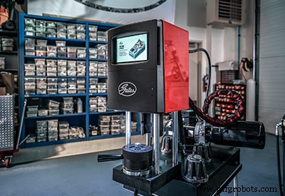
The industrial world continues to find new and creative ways to utilize Industry 4.0 concepts, and hose crimping technology is no different. Busy hose shops require speed and versatility, leaving little time for thumbing through catalogues looking for crimp specs. Many top crimp manufacturers offer high-end machines with touch screen HMIs employing wireless links to the manufacturer database.
This system might not be impressive for the technician who has memorized the crimp specs for their standard 100R1 or 100R2 assemblies. But when they’re asked to crimp various assemblies of stainless wrapped thermoplastic hose, they’ll be elated to know the required die information pulls up on the touchscreen. A quick selection of hose, dash size and stem results in readily available crimp specs populated right into the crimper settings.
Just like the fluid power industry at large, crimping technology will continue to advance. Expect to see augmented reality identify the hose and fittings visually, such as with QR codes, then automatically populate crimp specifications. Expect hydraulic hose crimping technology to become more versatile, more productive and more easily maintained.
Equipo industrial
- Actuador hidráulico a eléctrico:Discutiendo los conceptos básicos
- Cómo reemplazar una manguera hidráulica
- La evolución del servicio dinámico de Houston
- La evolución de la visión 3D
- ¿Por qué mi manguera hidráulica tiene fugas?
- Cómo desconectar una manguera hidráulica de un tractor
- Cómo identificar los accesorios de manguera hidráulica correctos
- Qué determina la velocidad de un motor hidráulico
- dónde está la bomba hidráulica en un tractor
- ¿Qué determina la velocidad de un motor hidráulico?
- ¿Cuáles son las 2 clasificaciones de las bombas hidráulicas?