


Deslizador de cámara motorizado controlado por Bluetooth Arduino
Componentes y suministros
 |
| × | 1 | |||
 |
| × | 1 | |||
| × | 1 | ||||
| × | 4 | ||||
| × | 4 | ||||
| × | 4 | ||||
| × | 4 | ||||
| × | 2 | ||||
| × | 2 | ||||
| × | 2 | ||||
| × | 2 | ||||
| × | 2 | ||||
| × | 4 | ||||
| × | 4 | ||||
| × | 8 | ||||
| × | 2 | ||||
| × | 1 | ||||
| × | 1 | ||||
| × | 1 | ||||
| × | 1 | ||||
| × | 1 | ||||
| × | 1 | ||||
| × | 1 | ||||
| × | 1 |
Herramientas y máquinas necesarias
 |
|
Aplicaciones y servicios en línea
 |
| |||
| ||||
 |
|
Acerca de este proyecto
Descripción general del proyecto
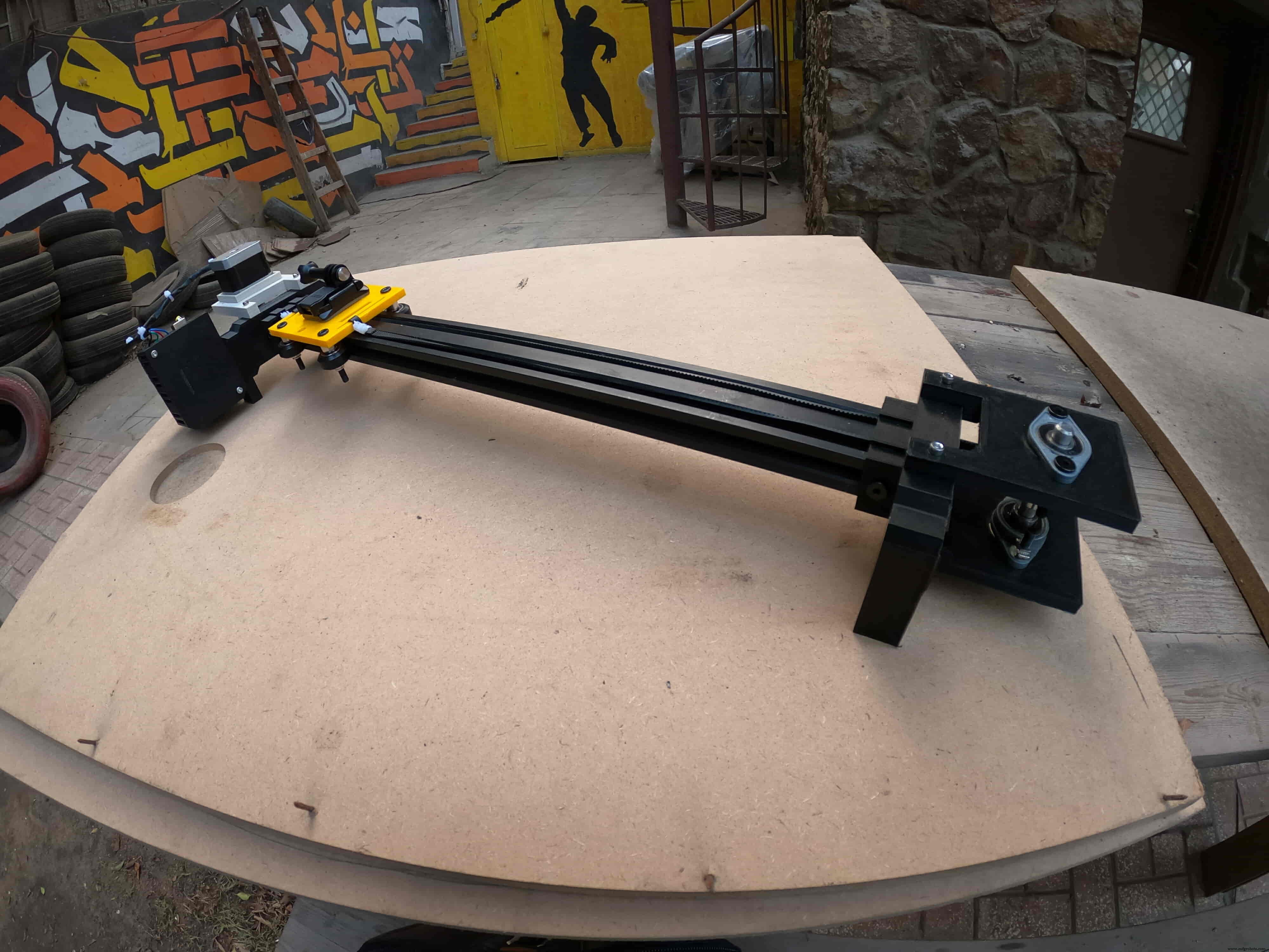
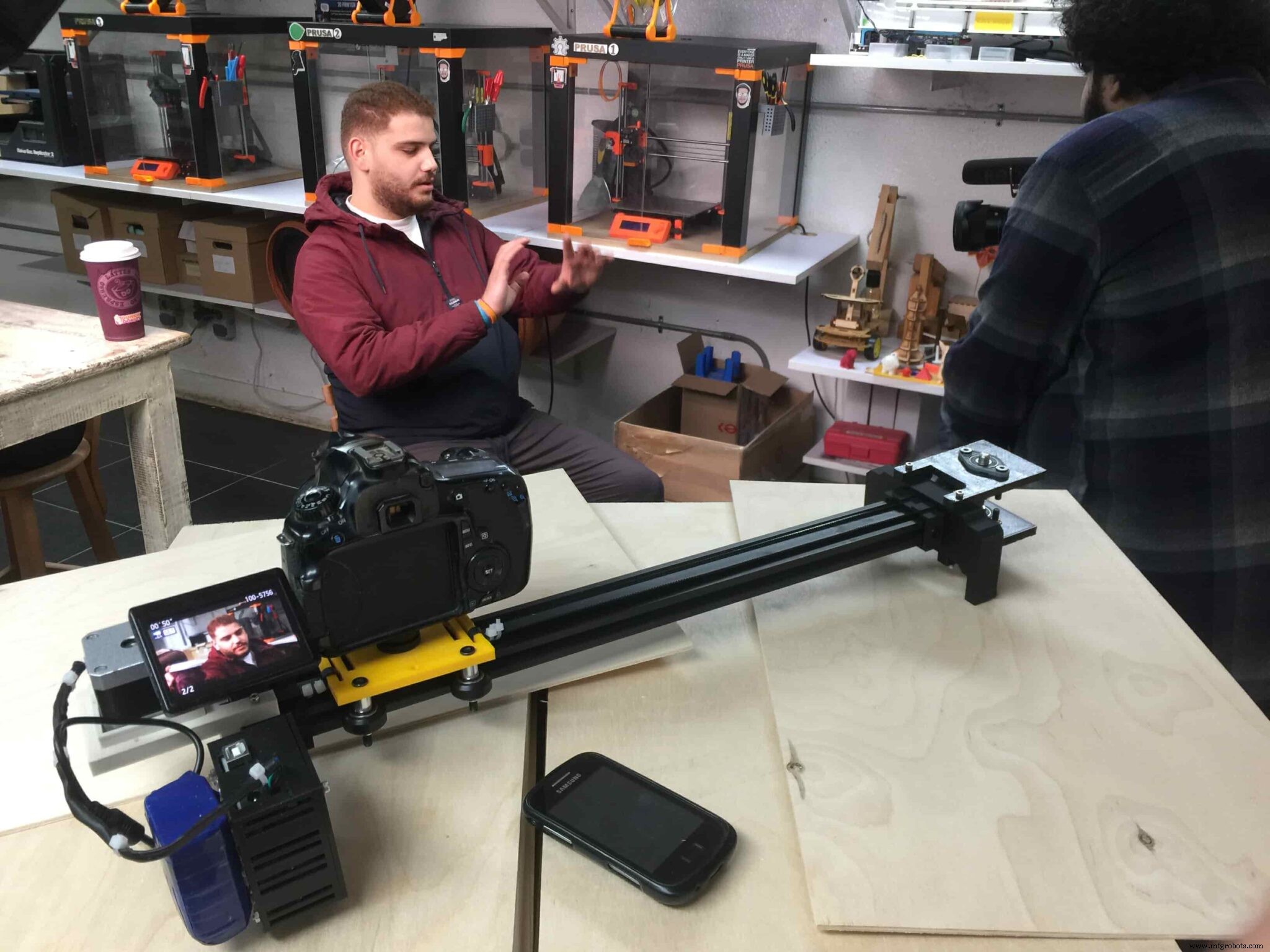
Para alguien a quien le encanta grabar videos aleatorios de aficionados, de alguna manera es caro comprar un control deslizante de cámara motorizado. Entonces, construí el mío. En este tutorial, repasaremos cada paso para construir su propio control deslizante de cámara motorizado controlado por Bluetooth.
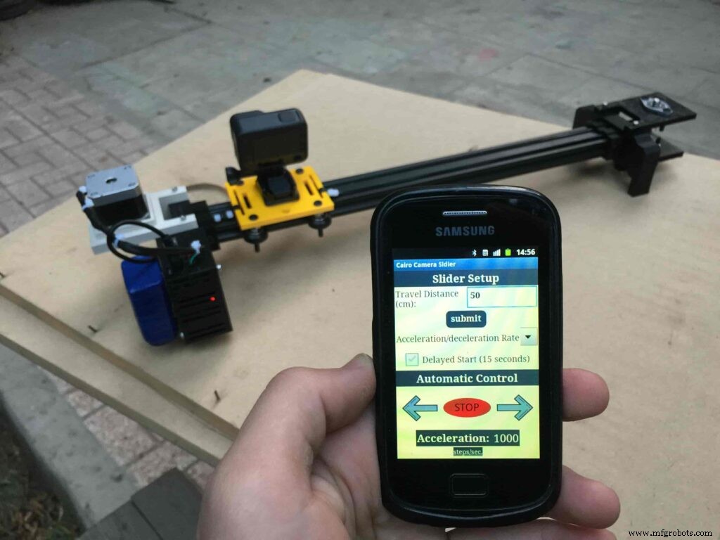
Hoy construiremos un control deslizante de cámara motorizado que podemos controlar de forma inalámbrica a través de Bluetooth desde una aplicación móvil Android hecha a medida. Usé la herramienta “MIT App inventor” para hacer la aplicación que nos da la capacidad de controlar muchas cosas como la velocidad de movimiento del control deslizante, la distancia de viaje, la tasa de aceleración / desaceleración y mucho más. La aplicación móvil es muy robusta, dentro de la aplicación puede configurar la longitud del control deslizante de la cámara que está utilizando. lo que significa que puede construir el control deslizante de su cámara real con cualquier longitud de hasta 10 metros sin preocuparse por la aplicación.
Usamos un motor paso a paso NEMA17 como actuador para poder controlar cuántos pasos necesitamos que se mueva el control deslizante de la cámara. Para controlar un motor paso a paso usando la placa Arduino, necesitamos un traductor que tome los comandos de la placa Arduino y los traduzca al idioma que entiende el motor paso a paso. Aquí viene la función de controlador del motor paso a paso A4988 Pololu, que nos brinda cinco resoluciones de micropasos diferentes (hasta 1/16 de paso) para lograr la máxima precisión de movimiento y suavidad de movimiento.
Este proyecto se diseñó teniendo en cuenta la capacidad de creación en un fablab / makerpace / hackerspace.
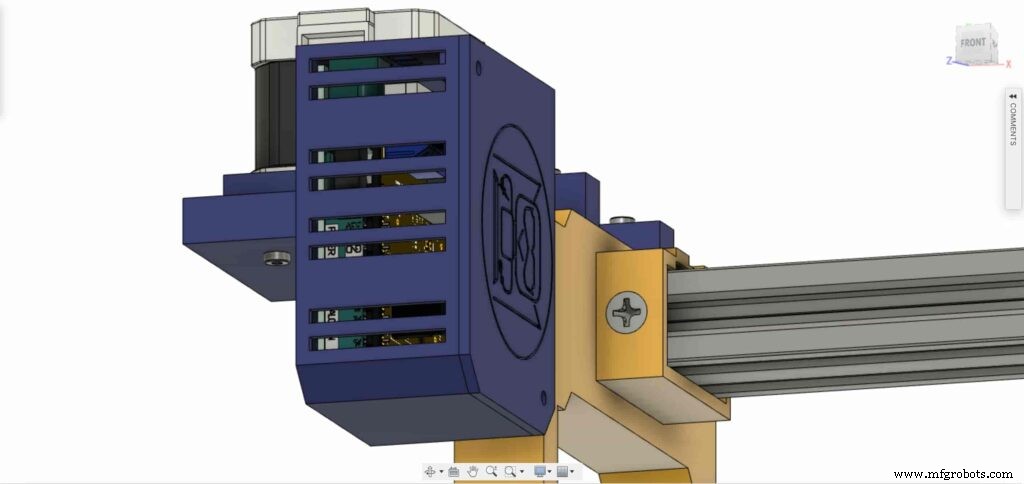
Modelado CAD y 3D
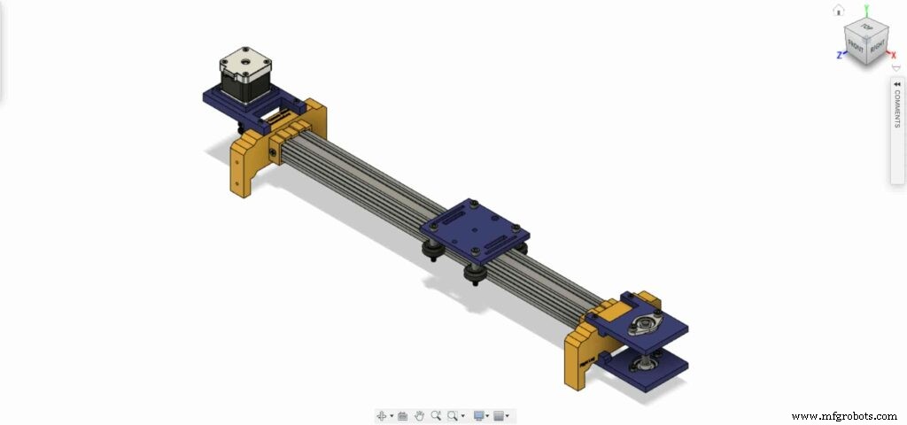
Usamos Fusion360 para diseñar el control deslizante de la cámara, elegimos usar componentes mecánicos muy conocidos y fáciles de encontrar que puede comprar fácilmente en casi cualquier tienda en línea o fuera de línea, sin importar dónde viva.
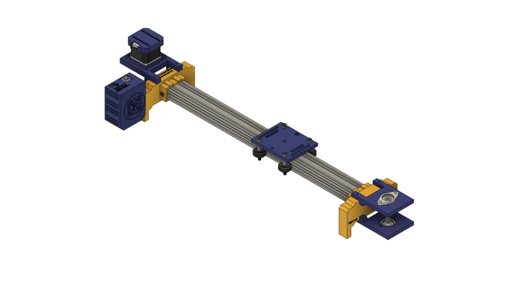
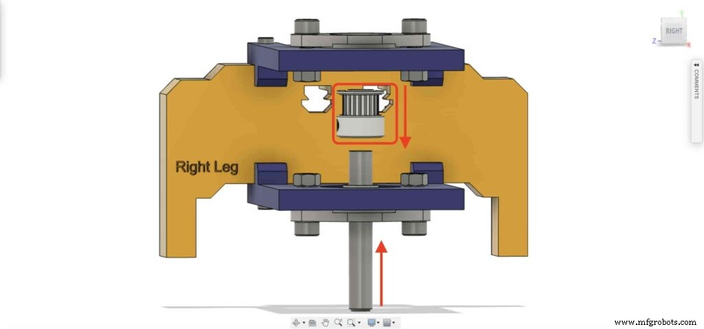
Estamos utilizando hardware Openbuilds para construir la estructura mecánica, el riel lineal 2040 con ranura en V como guía para que la cámara avance. Dos poleas, una en el eje del motor paso a paso. Y el otro, en un eje de riel lineal de 8 mm en el lado opuesto del control deslizante con una correa de distribución abierta entre ellos para convertir el movimiento giratorio del motor paso a paso en movimiento lineal.
El eje del riel lineal de 8 mm se instala entre dos cojinetes de bloque de brida de almohada autoalineables que se instalan en la placa superior e inferior mediante cuatro tornillos M5.
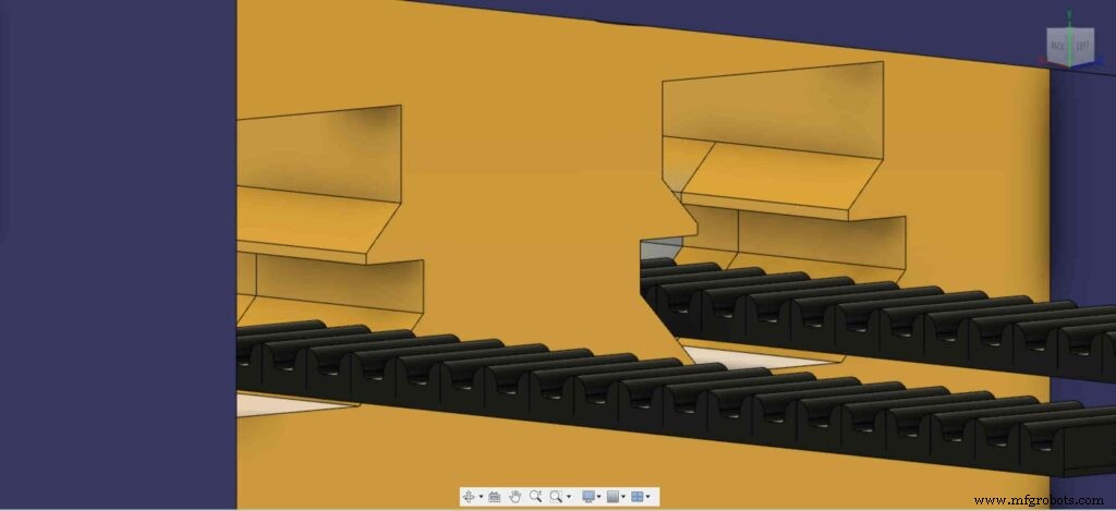
Estamos usando cuatro ruedas sólidas Delrin V-Slot que se deslizan hacia abajo en la ranura en V del riel V-Slot para hacer que el movimiento de la cámara sea extremadamente suave. El centro de la placa de la cámara tiene un orificio de 1/4 de pulgada de diámetro para un tornillo de trípode estándar para que pueda montar su cámara fácilmente.
Por último, una caja para la electrónica, todas las partes del control deslizante de la cámara se fijan juntas con tornillos y tuercas m3 * 16 mm.
Fabricación digital (impresión 3d)
Todo el cuerpo del control deslizante de la cámara está impreso en 3D con una altura de 0,2 capas, un 20% de relleno, excepto el control deslizante de la cámara izquierda y la pierna derecha, están impresos con una altura de 0,2 capas y un 50% de relleno.
puede descargar los archivos STL desde Thingiverse.
Conjunto del kit de rueda en V
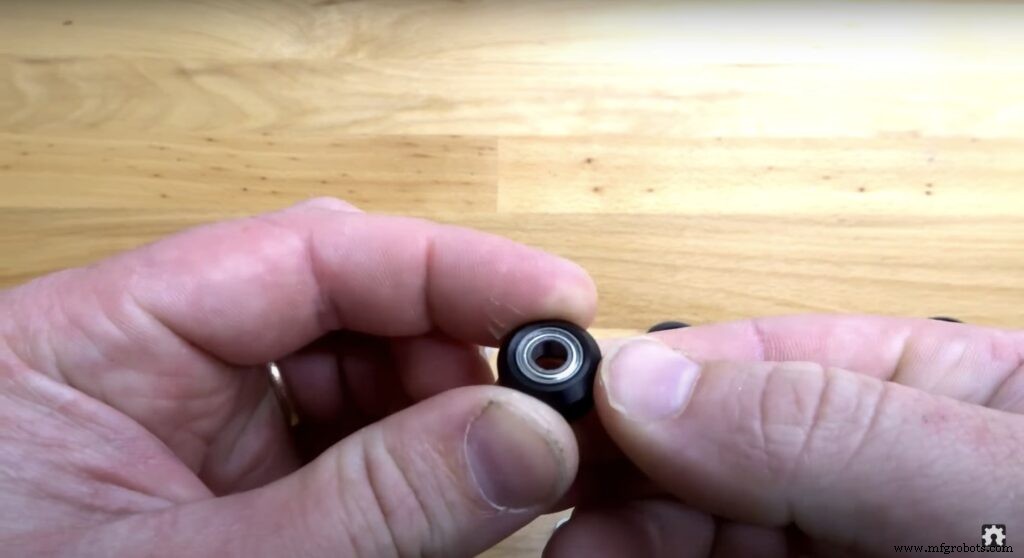
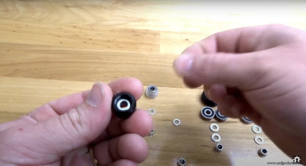
El proceso de montaje es muy fácil, ¡vamos! En el primer paso, necesitamos ensamblar las cuatro ruedas en V sólidas. El kit de rueda en V sólida viene con una rueda de goma, dos cojinetes, dos lainas de percisión y una contratuerca.
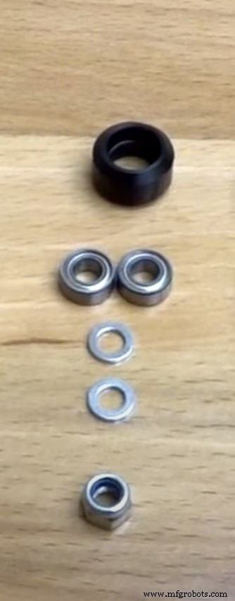
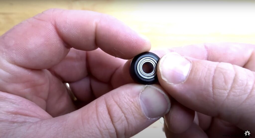
Inserte el cojinete de un lado de la rueda de goma y gire la rueda, luego inserte una cuña de precisión dentro de la rueda de goma, por último inserte el segundo cojinete desde el segundo lado de la cara.
Conjunto mecánico del control deslizante de la cámara
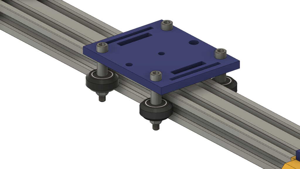
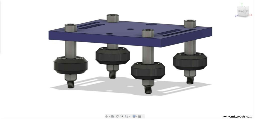
Primero, necesitamos ensamblar la placa de la cámara y las cuatro ruedas en V sólidas. utilizando el espaciador de aluminio de 9 mm, la cuña de precisión y la contratuerca.
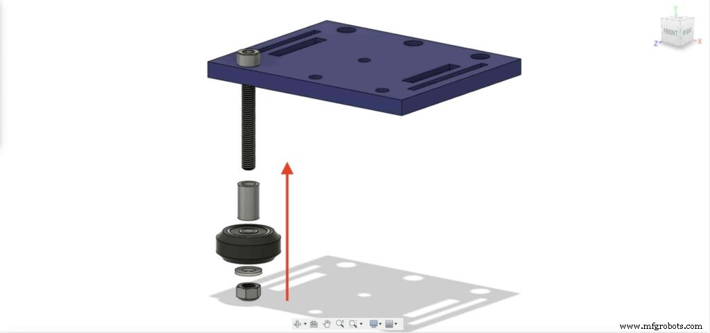

Vamos a repetir el paso anterior con las otras tres ruedas. en las dos ruedas de la derecha, usaremos el espaciador de 9 mm. Y las otras dos ruedas izquierdas vamos a utilizar el espaciador excéntrico con un espaciador de 3 mm en lugar del espaciador de 9 mm.
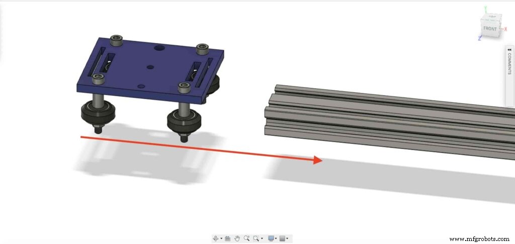
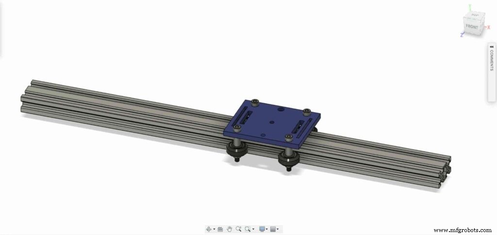
Ahora, inserte la placa del soporte de la cámara en el perfil de la ranura en V. Si descubrió que la placa está suelta y se mueve, puede apretar la tuerca excéntrica hasta obtener una placa sólida.
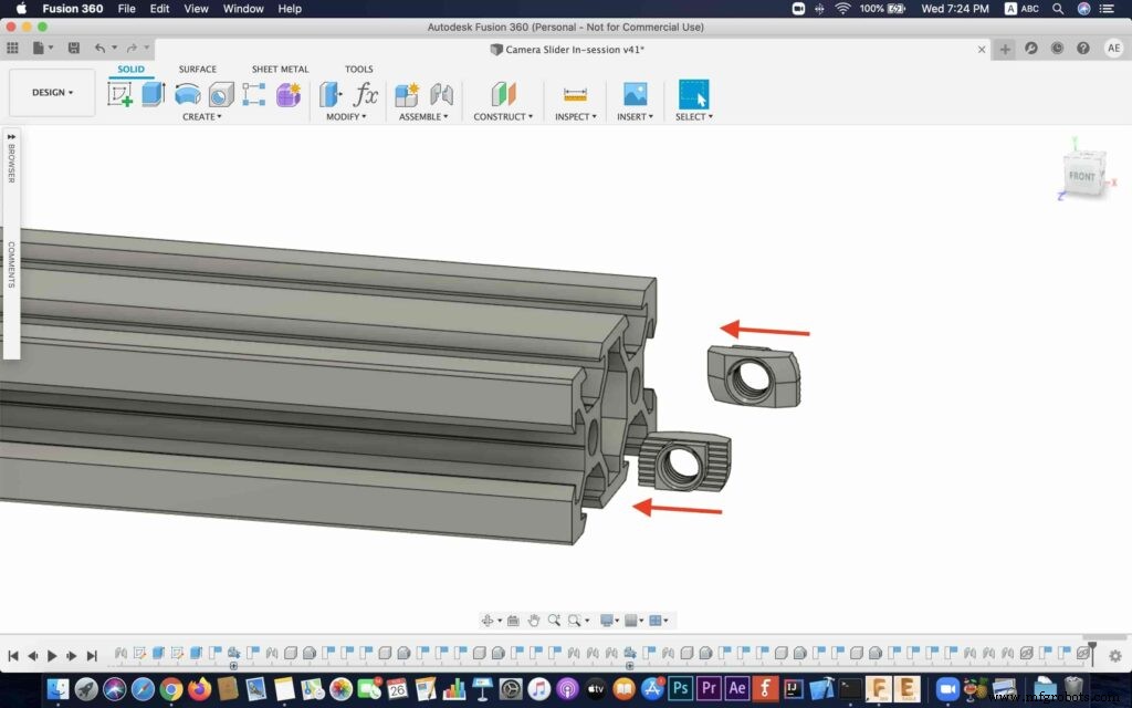
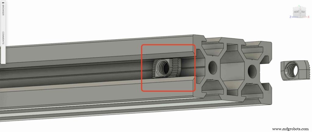
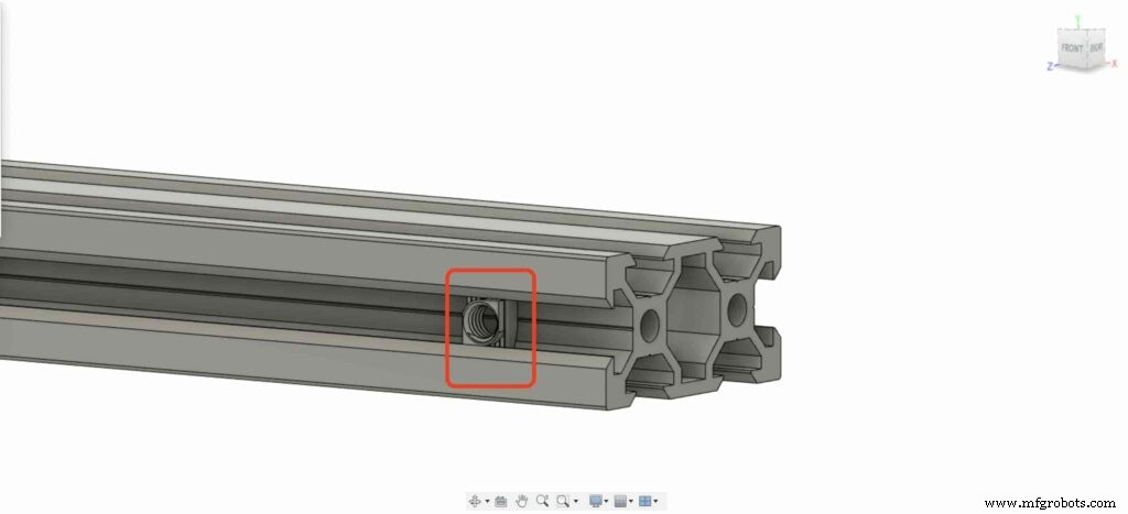
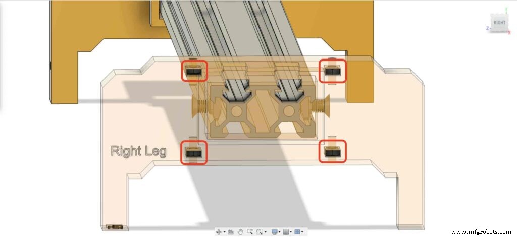
Insertemos dos tuercas en T en cada extremo del perfil de la ranura en V. necesitamos conectar el perfil de la ranura en V con las patas derecha e izquierda del control deslizante de la cámara.
Tome las dos patas del control deslizante de la cámara y empújelas hacia el perfil de la ranura en V.
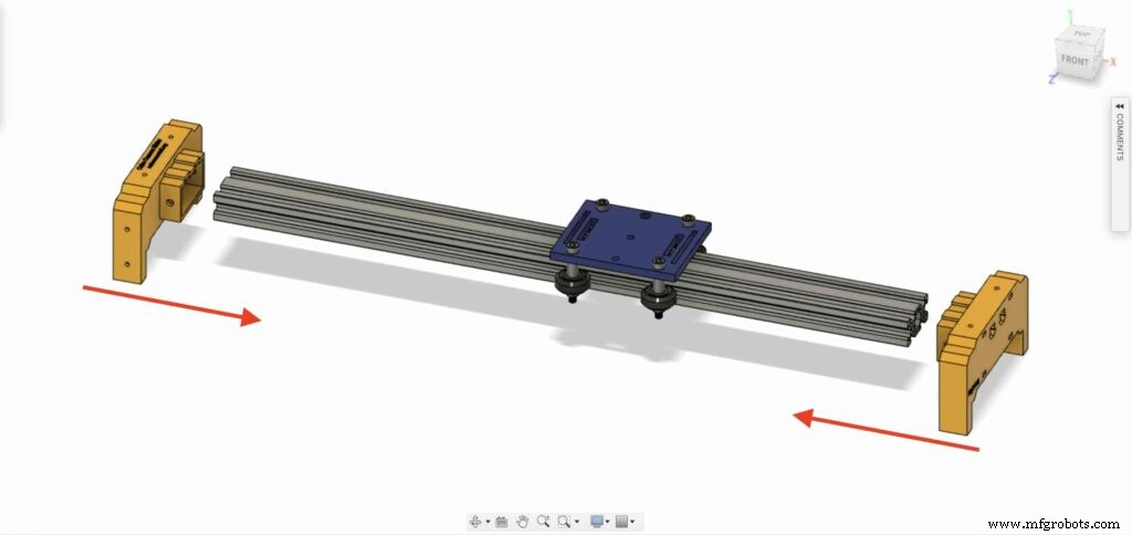

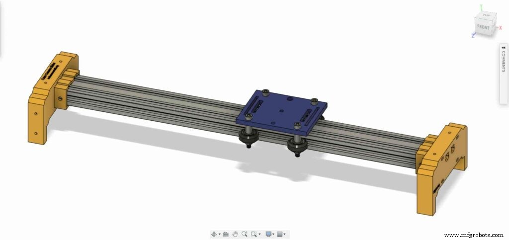
traiga cuatro tornillos M5X10mm y fije las dos patas con el perfil de ranura en V.
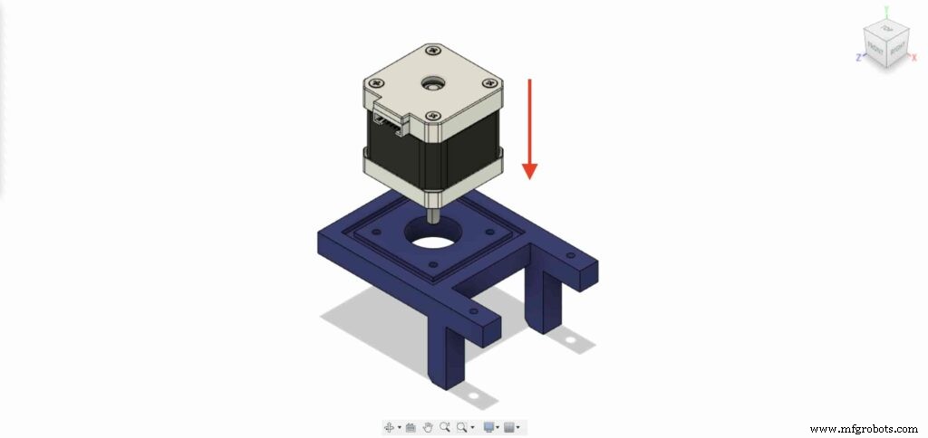
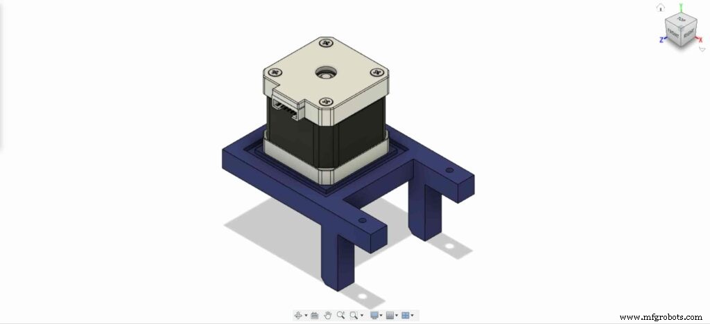
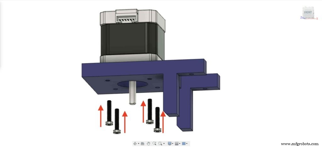
Necesitamos instalar el motor paso a paso NEMA 17 en su placa. luego, usando cuatro tornillos M3X16mm vamos a fijar el motor en su lugar.
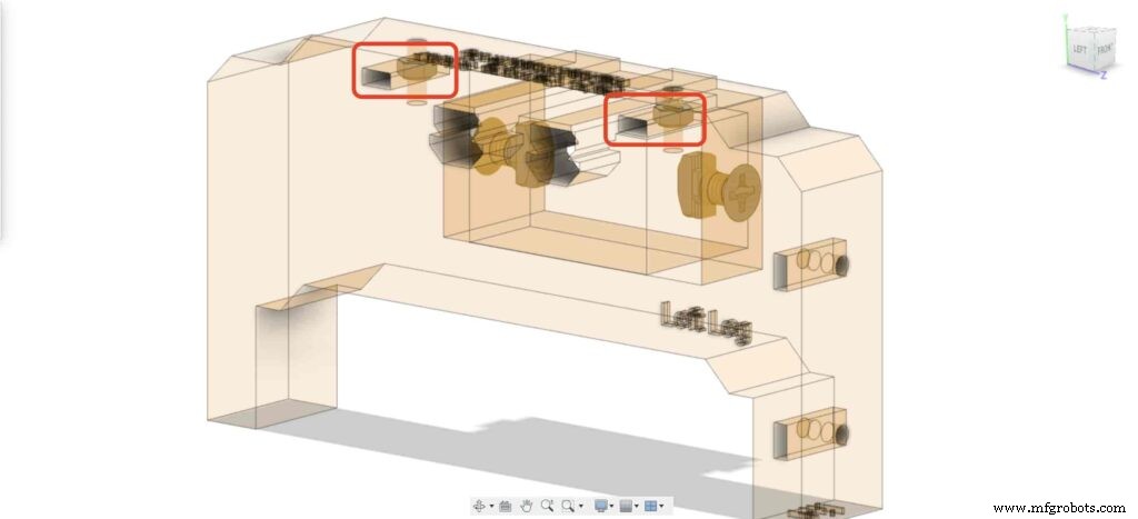
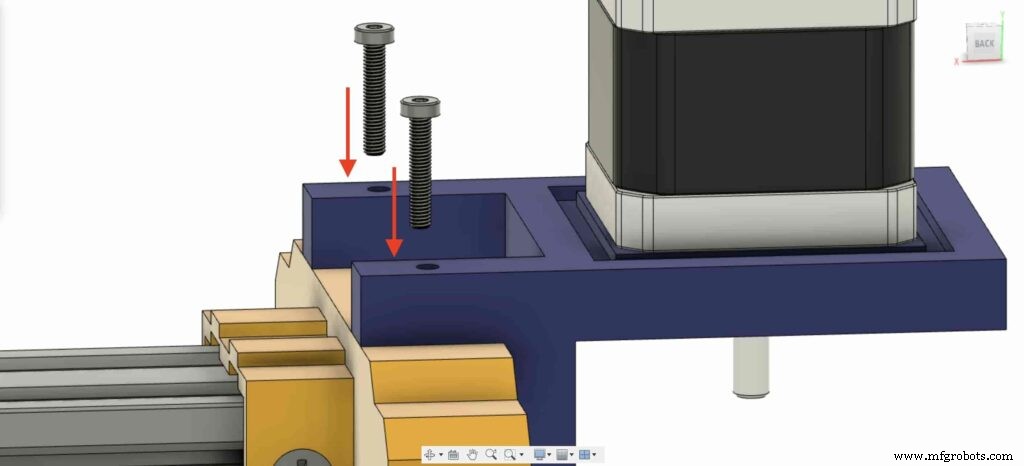
En la pierna izquierda, inserte dos tuercas dentro del lugar de las tuercas superiores de la pierna izquierda.
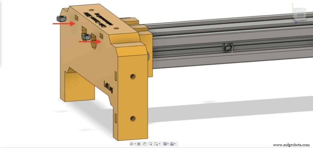
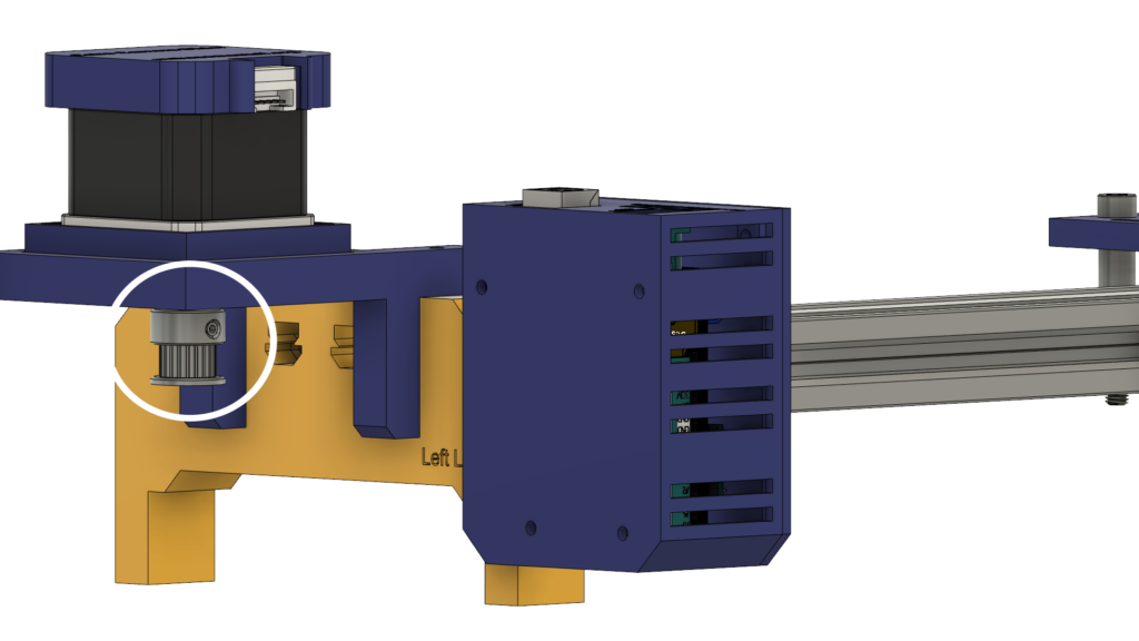
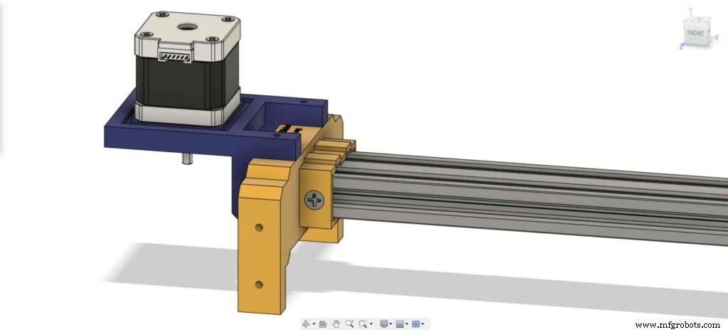
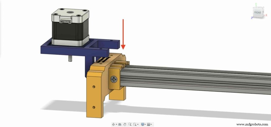
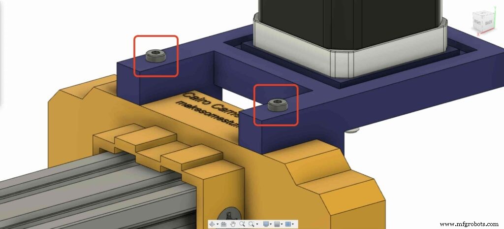
Traiga la placa del motor NEMA 17 y fíjela en la parte superior de la pata izquierda. y con dos tornillos M3X16mm vamos a fijar la placa en la pata izquierda.
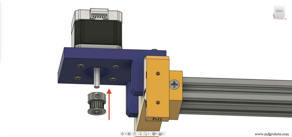
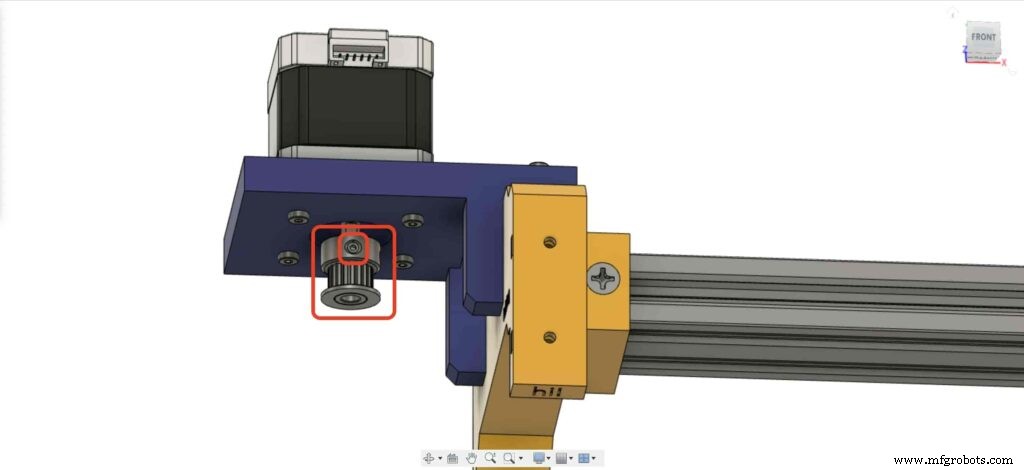
Para poder convertir el movimiento de rotación del motor paso a paso en movimiento lineal, necesitamos instalar una polea GT2 Bore de 5 mm en el eje del motor. y usando la llave Allen, apriete el tornillo de fijación de la polea para mantenerla en su lugar.
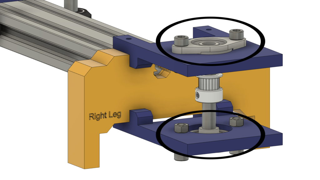
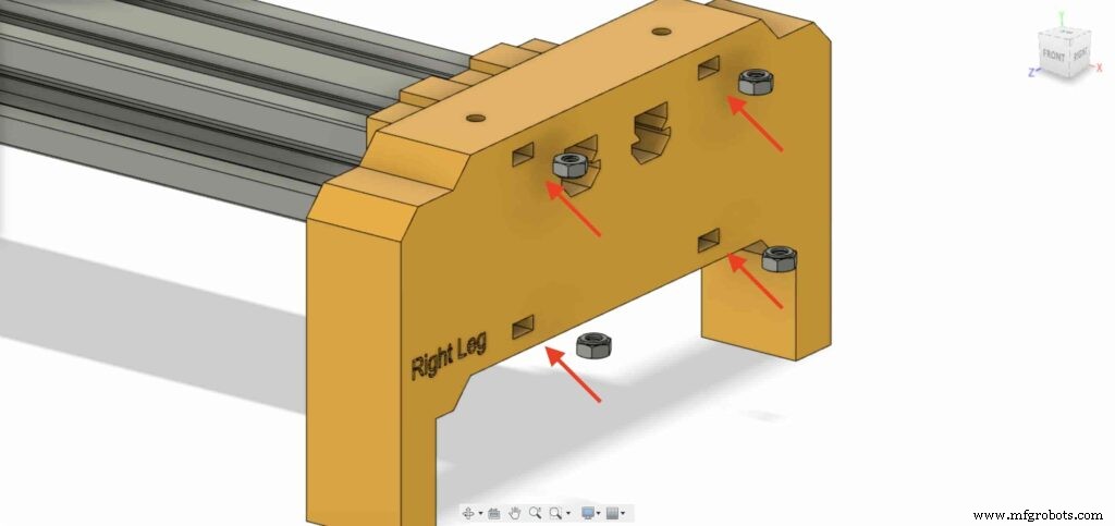
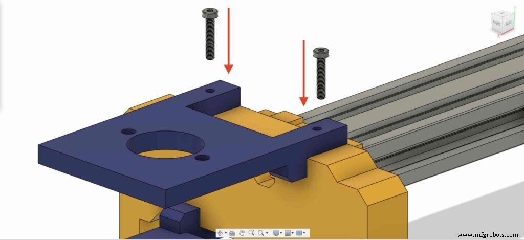
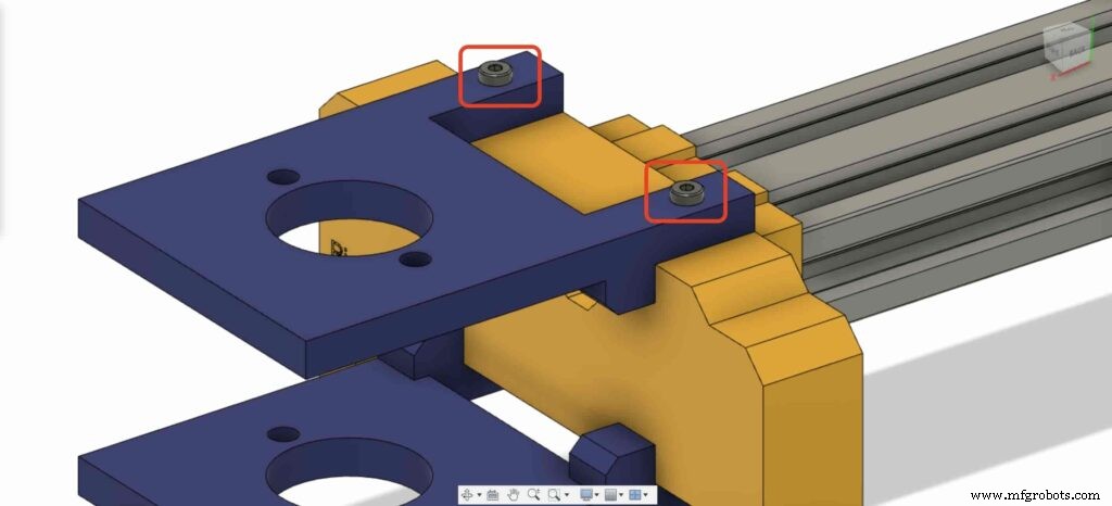
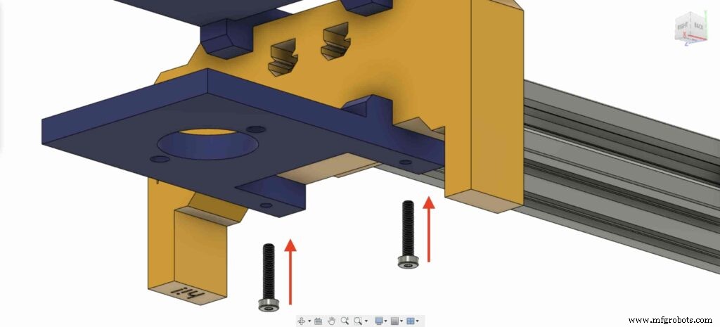
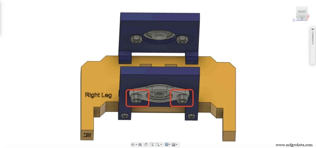
Vayamos a la pata derecha del control deslizante de la cámara, inserte cuatro tuercas M3 en el lugar de las tuercas de la pata.
Luego, coloque los cojinetes de la pierna derecha dos placas en la parte superior de la pierna derecha del control deslizante de la cámara.
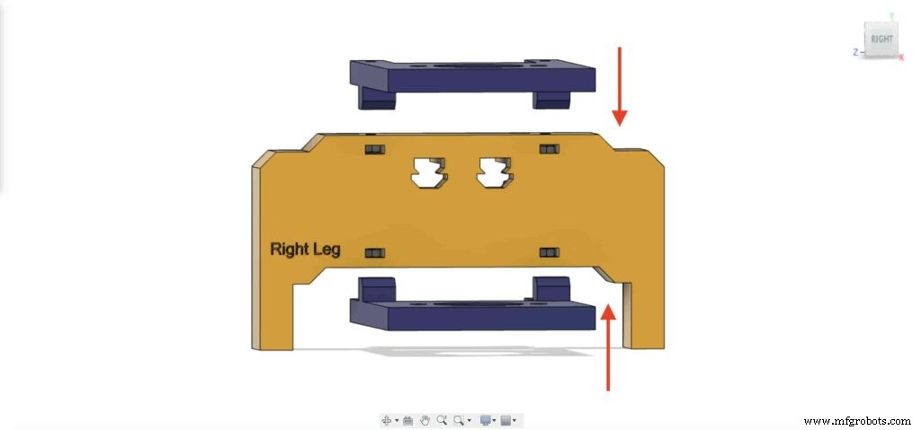
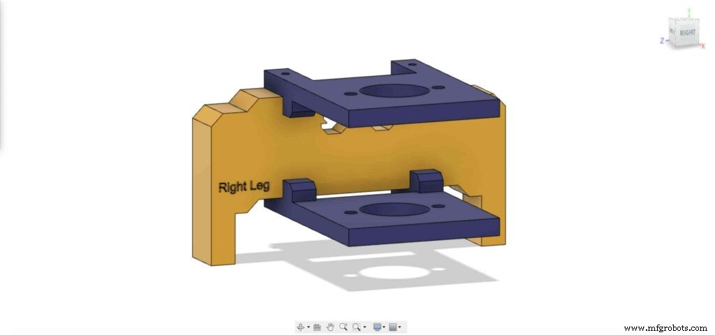
Con cuatro tornillos M3X16mm, fije las dos placas en la pata derecha del control deslizante de la cámara para mantenerlas en su lugar.
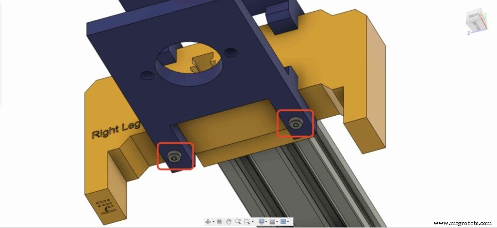
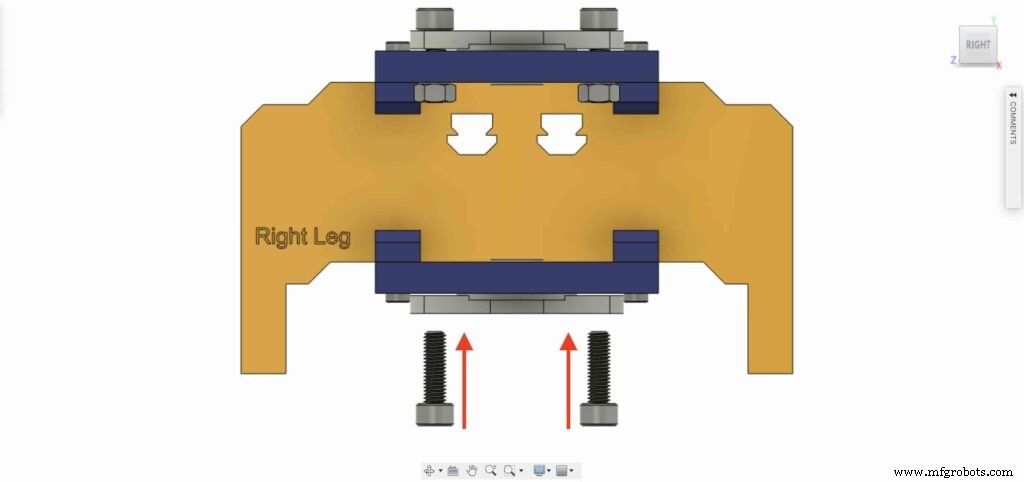
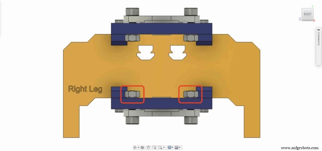
Traiga uno de los cojinetes de bloque de brida de 8 mm e instálelo en la placa de la pata superior derecha. utilizando dos tornillos M5X20mm y dos tuercas M5.
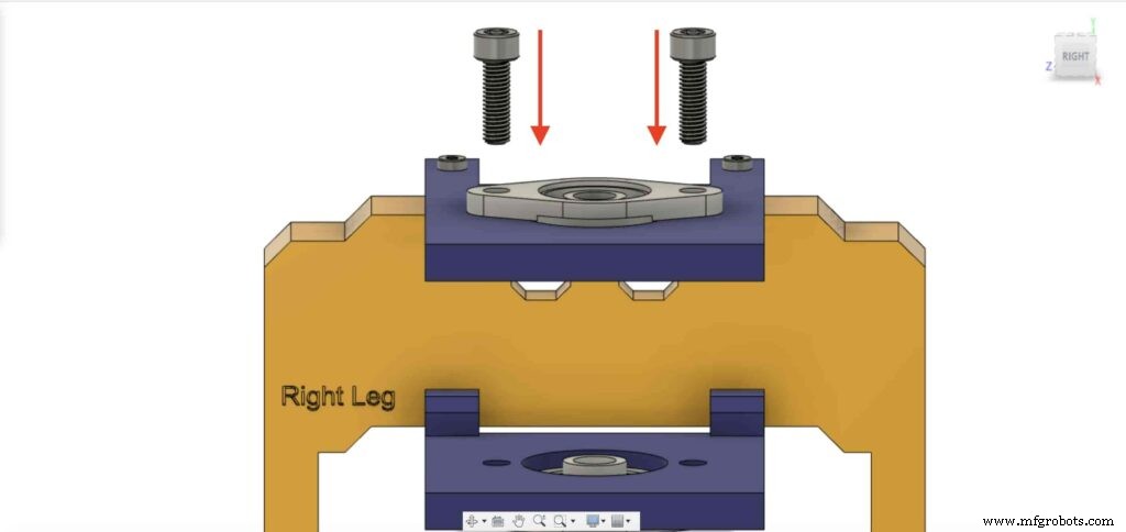
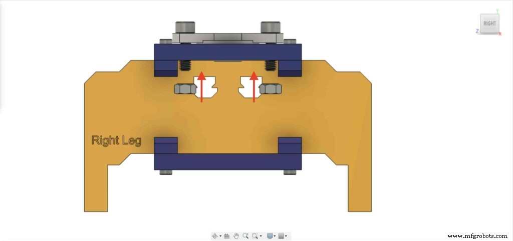
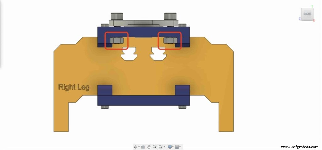
Necesitamos repetir el paso anterior con el segundo bloque de rodamiento de brida de 8 mm para fijarlo en la placa inferior de la pata derecha del control deslizante de la cámara.
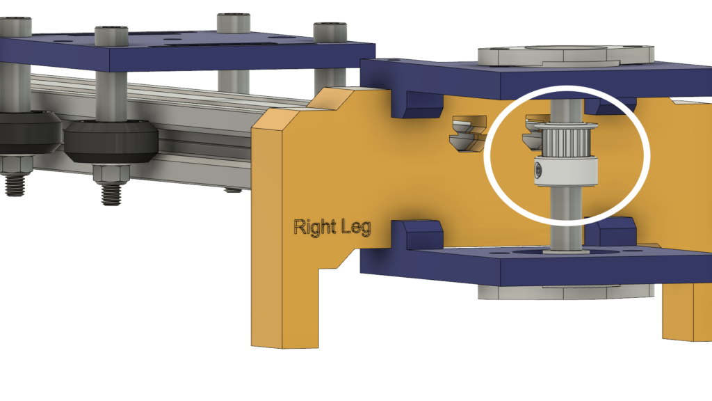
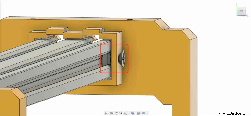
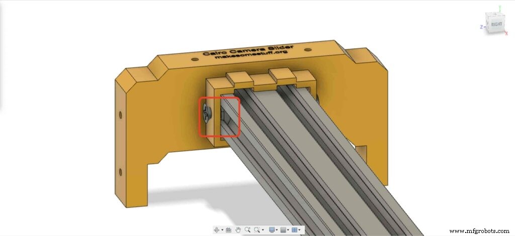
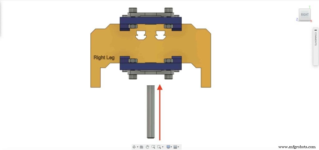
Inserte el eje del riel lineal de 8 mm en el bloque de rodamiento de la brida de 8 mm desde la parte inferior y empújelo hacia arriba. Luego, inserte la polea de 8 mm de diámetro en el eje del riel lineal y fíjela apretando el tornillo de fijación de la polea.
Checkpoint, ahora ensamblamos todo el mecanismo deslizante de la cámara excepto una cosa. la correa de distribución. Hagámoslo.
Gire la correa de distribución de 6 mm en la polea de 5 mm de diámetro interior del motor NEMA17. Además, en la polea de 8 mm de diámetro de la pata derecha. Por último, apriete el cinturón con la placa de la cámara.
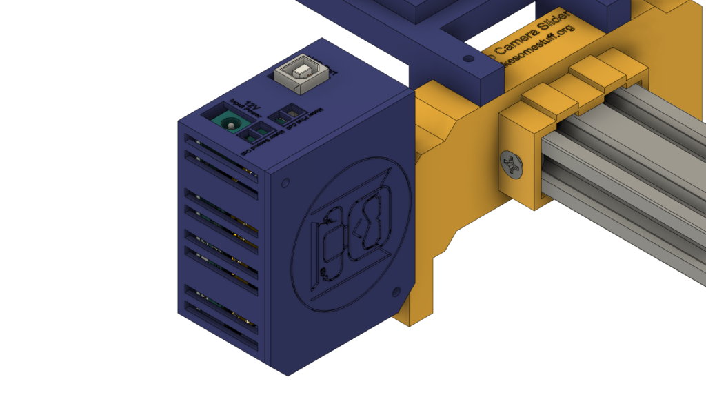
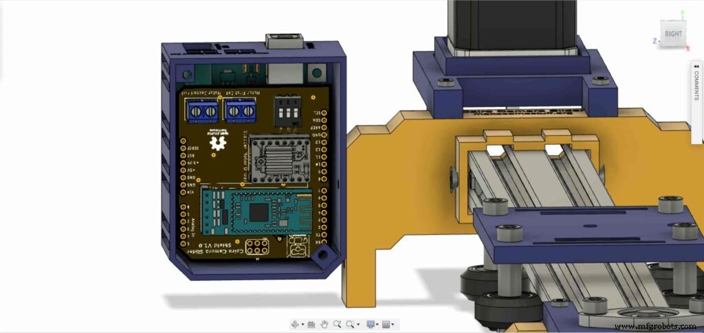
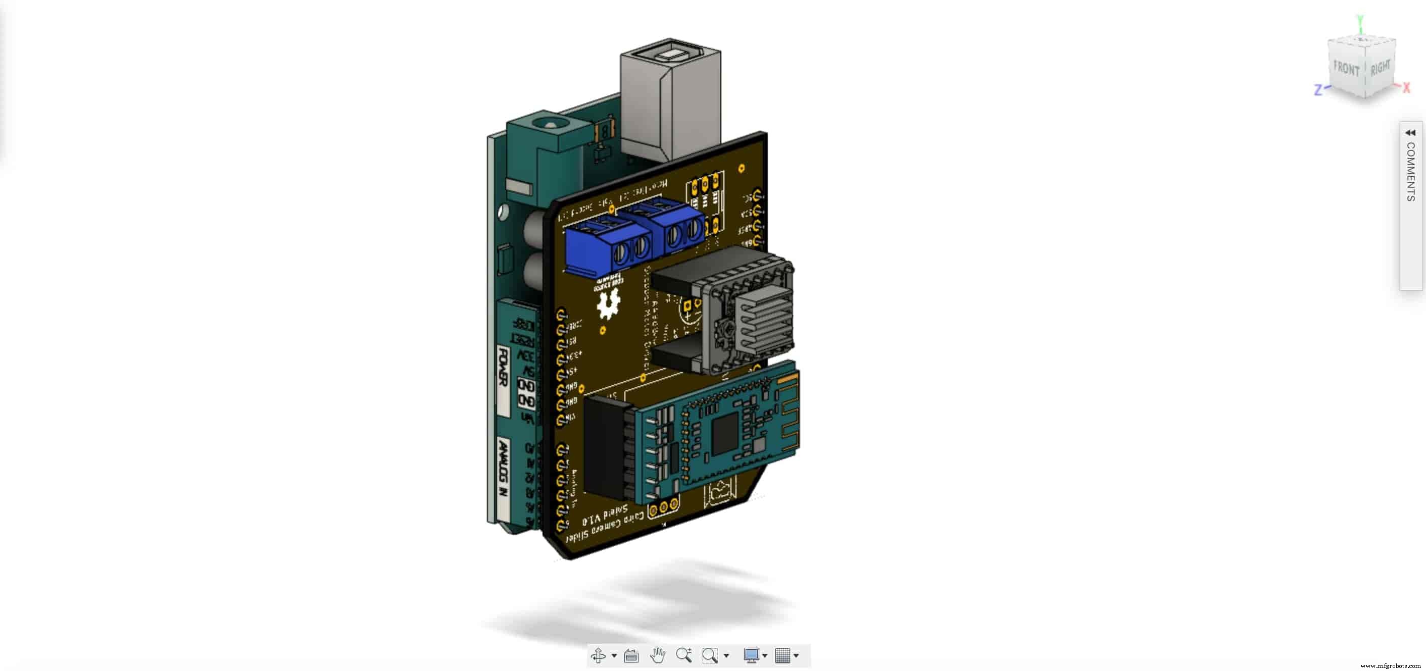
Es hora de montar el tablero de control. inserte el protector Arduino de Cairo Camera Slider en la parte superior de la placa Arduino.
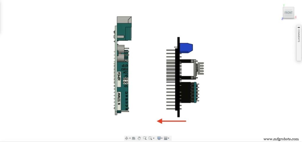
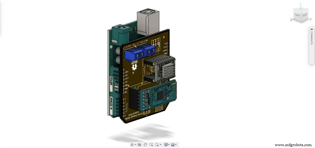
Inserte la placa Arduino y el protector deslizante de la cámara Cairo dentro de la caja de la placa de control.
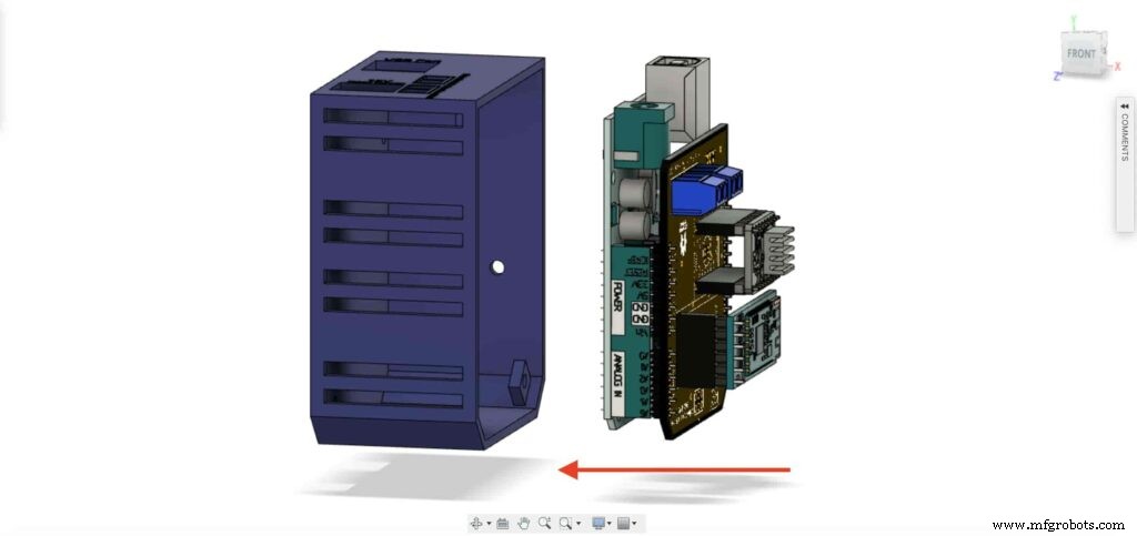
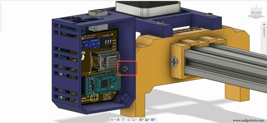
inserte dos tuercas M3 dentro del lugar de las tuercas de la pata izquierda.
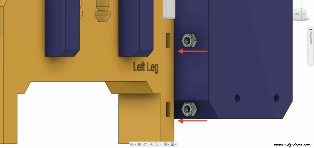
instale la caja de la placa de control en la pata izquierda del deslizador de la cámara Cairo con tornillos M3X16mm.

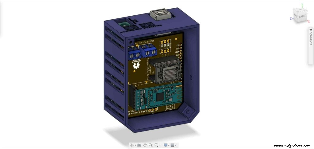
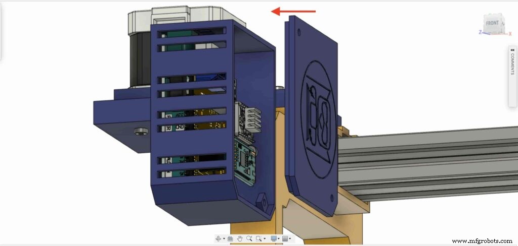
cierre la cara superior de la caja del gabinete con dos tornillos y tuercas M3, ¡y listo!

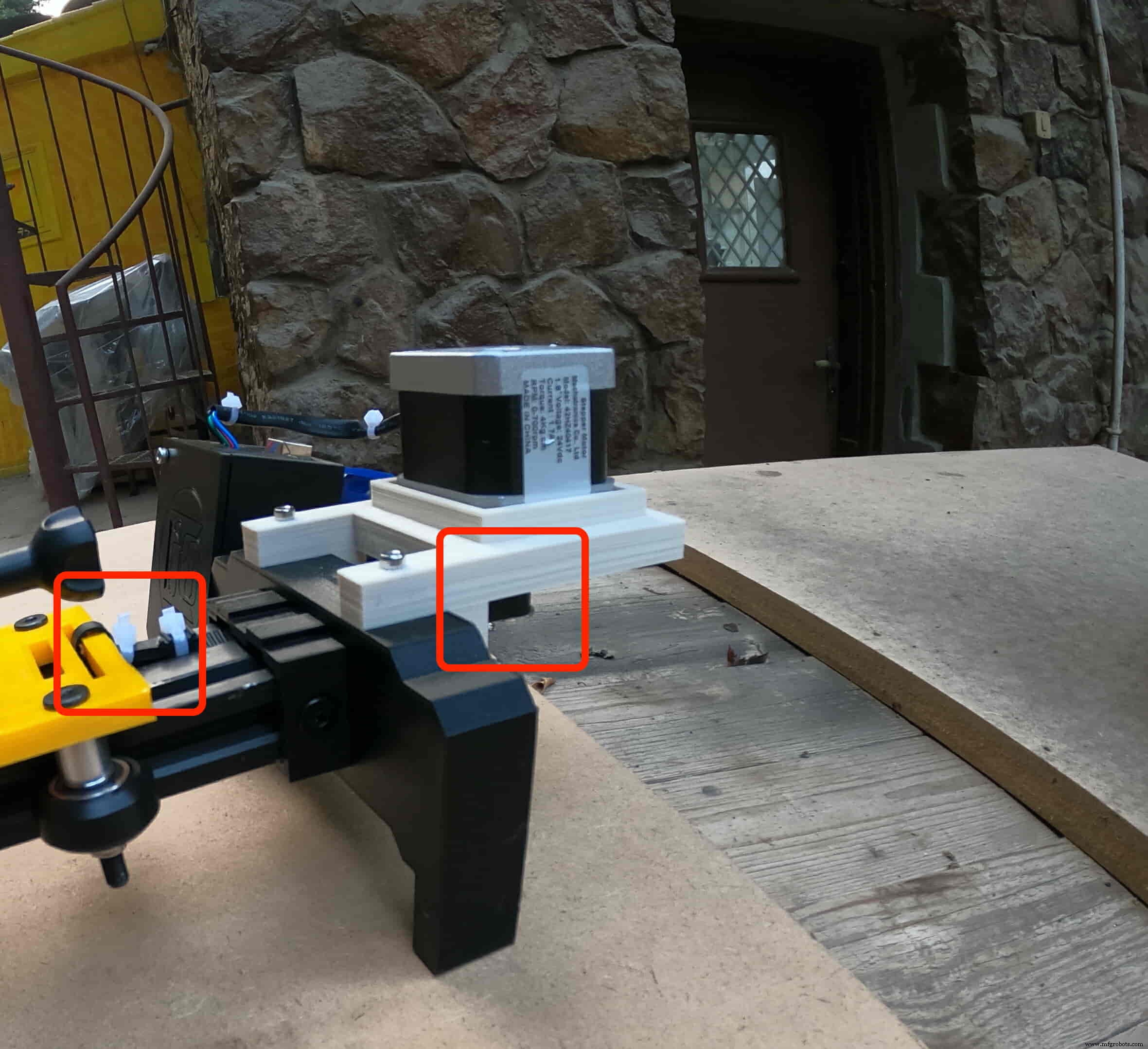
Control de prueba de motor paso a paso
Después de ensamblar todas las piezas, debemos probarlo para asegurarnos de que todo esté instalado en su lugar correctamente. Now, we need to connect the stepper motor with the Arduino board through the A4988 stepper motor driver and write some code to run that thing.
A4988 stepper motor driver
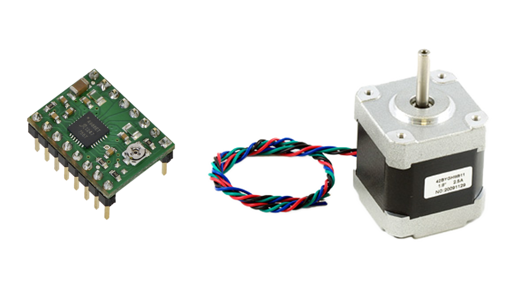
To control any stepper motor using the Arduino board or any microcontroller, you will need a stepper motor driver which works as a translator, takes commands from the Arduino board and translate it to the language that the motor understands.
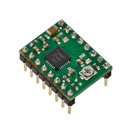
there are a lot of stepper motor drivers out there but we will use the A4988 driver . This driver allows us to control one bipolar motor at up to 2A output current per coil, it’s very simple to interface with the Arduino board you only need two digital pins to fully control your motor step and direction, allows you to control the maximum current output easily with an onboard potentiometer, and gives you a micro-step resolution down to 1/16 micro-step.
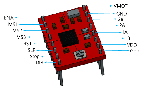
VMOT, GND: It’s the power connection pins for the stepper motor itself, it can be 8V-35V. In our case, we are connecting a 12V 3A power source on those pins with a 100uf decoupling capacitor to protect the A4998 board from any power spikes.
2B, 2A: the output pins for the stepper motor first coil which can deliver up to 2A.
1A, 1B: the output pins for the stepper motor second coil which can deliver up to 2A as well.
VDD, GND: Used for driving the internal logic circuitry, it can be 3V to 5.5V. It’s totally isolated from the VMOT pin.
EN: Stands for “Enable” it’s an active LOW(0V) input pin, which means when this pin pulled LOW(0V) the A4988 chip is enabled. And when pulled HIGH(5V) the A4988 chip is disabled. By default, this pin is pulled LOW(0V). So, the chip is always enabled unless you pull it HIGH(5V).
MS1, MS2, MS3: Through these pins, you can select your motor microstepping resolution(step size). The A4988 gives you five different microstep resolutions (full step, half step, quarter step, Eighth step, Sixteenth step) . By applying appropriate logic levels to these three pins we can set the motors to one of the five step resolutions.
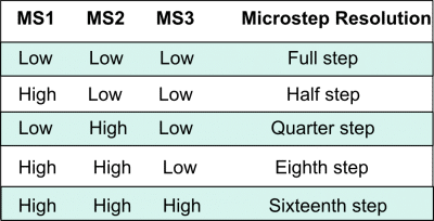
By default, the MS1, MS2, MS3 pins have internal pull-down resistors. So leaving these three microstep selection pins disconnected results in full-step mode.
RST, SLP: The “Reset” pin is an active LOW(0V) input pin, which means when it pulled LOW(0V), all the step inputs are ignored it also resets the translator itself until you pull it HIGH(5V). The “Sleep” pin also an active LOW pin, pulling it LOW, puts the driver in the sleep mode minimizing the power consumption. By default, the “Sleep” pin is pulled HIGH(5V).
STP, DIR: The “Step” pin is responsible for controlling the number of steps that the motor is rotating, each pulse to the “Step” pin corresponds for one microstep in the direction selected by the “Direction” pin, the faster the pulses, the faster the motor will rotate. By applying logic value HIGH(5V) on the “Direction” pin it makes the motor rotate clockwise, by applying LOW(0V) it makes the motor rotate counterclockwise(it may differs from one to another according to your motor wiring with the driver).
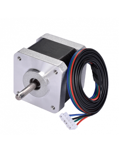
NEMA17 Stepper Motor
Stepper motors are DC motors that can rotate in precise increments, they are used in many applications like 3D printers to align the printhead and CNC machines to control the movement of the cutting tool and this is because they are very accurate and precise.
Unlike DC motors, stepper motors are controlled by applying DC electrical pulses to their internal coils. Each pulse makes the shaft advance by one step or a fraction of step which is called “Microstepping”. So, you can control precisely how many steps or even fraction steps you want the motor shaft to move. Another great advantage of using stepper motors is that it can move very precisely and accurately at very slow speeds without even stalling.
The type of motor we are using in this project is the NEMA 17 Bipolar stepper motor . The bipolar stepper motor has two internal coils and it usually has four wires, two wires per coil. unlike the Bipolar stepper motor which has five wires. The “Step Angle” of the motor is 1.8° which indicates how much the shaft advances in each full step, the motor works on 9V but if you want to get the maximum power of it use a 12V power source.
So, by connecting the stepper motor with the A4988 stepper motor driver, we can control how many steps we need the motor to move and in what direction. Also, we can set the “microstep” mode is it full step, half step, quarter step, ….. Let’s take a look at the wiring diagram.
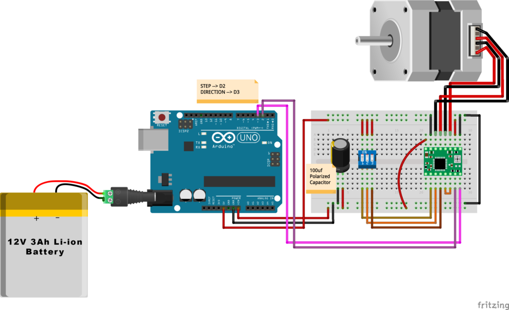
Wiring Diagram
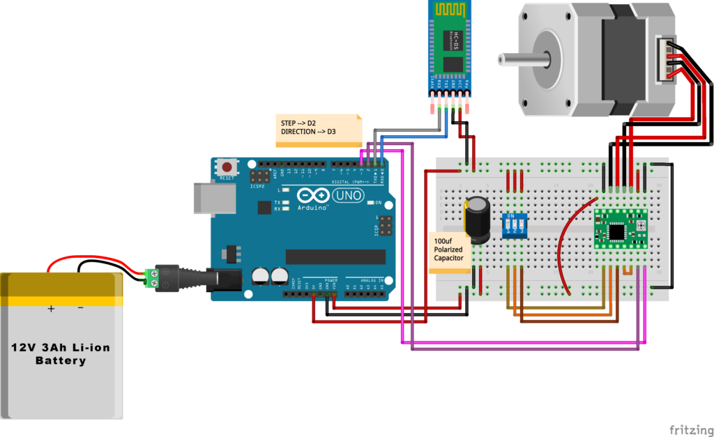
As we stated before, we need to make a small check to make sure that everything we assembled before is right in its place and moving properly. Now, we will wire all the hardware together, the NEMA 17 stepper motor with the A4988 stepper motor driver to the brain, the Arduino board. And using a 12V 3A Lithium-Ion battery to feed the motors with the power it needs.
Arduino Code
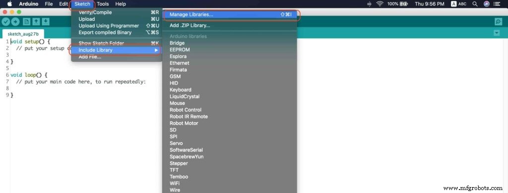
AccelStepper Library Installation
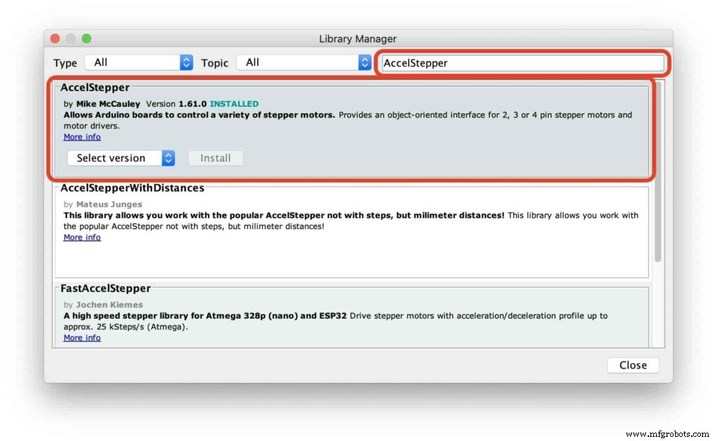
The Installation is pretty simple, we need to open Arduino IDE. From the “Sketch” menu. Select Include Library –> Manage Libraries…
A new window should appear, search for “AccelStepper” and install the library made by “Mike McCauley”. Easy right!
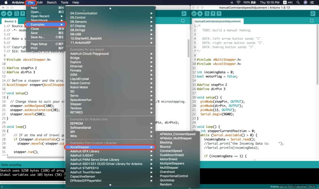
After installing the AccelStepper library, you should see it in the examples menu.
I wanna make sure that the AccelStepper library is installed correctly and my stepper motor connection with the A4988 motor driver is right and my power management is fine. So, let’s write some lines of code to run our stepper motor forward and backward.
// Bounce stepper test program
// Make a single stepper bounce from one limit to another
// Copyright (C) 2020 makesomestuff.org

#include
#define stepPin 2
#define dirPin 3 // Define a stepper and the pins it will use

AccelStepper stepper(AccelStepper::DRIVER, stepPin, dirPin); //create an object. the pin "2" is the step pin, "3" is the direction pin.

void setup()
{
 // Change these to suit your stepper if you want
 stepper.setMaxSpeed(100);
 stepper.setAcceleration(20);
 stepper.moveTo(500);
}

void loop()
{
 // If at the end of travel go to the other end
 if (stepper.distanceToGo() ==0)
 stepper.moveTo(-stepper.currentPosition());
 stepper.run();
}
The code logic is pretty straightforward, we initialized an object from the AccelStepper library, we defined two constants (stepPin, dirPin) that two digital pins is used by the A4988 stepper motor driver to control the movement of the motor itself.
#include

#define stepPin 2
#define dirPin 3 // Define a stepper and the pins it will use

AccelStepper stepper(AccelStepper::DRIVER, stepPin, dirPin); //create an object. the pin "2" is the step pin, "3" is the direction pin.
Inside the void setup function, we set the Max. speed of the stepper motor to 100 steps/sec. Also, we set the acceleration/deceleration rate to 20 steps/sec. lastly, we used the moveTo() function to tell the motor to move 500 steps.
void setup()
{
 // Change these to suit your stepper if you want
 stepper.setMaxSpeed(100);
 stepper.setAcceleration(20);
 stepper.moveTo(500);
}
Inside the void loop function, we are checking if the motor reached it’s position or not. If it reached the position, it will bounce back. and if it didn’t reach it’s position yet, it will keep running.
void loop()
{
 // If at the end of travel go to the other end
 if (stepper.distanceToGo() ==0)
 stepper.moveTo(-stepper.currentPosition());
 stepper.run();
}
Camera Slider Full Wireless Control
We have done great things so far. Let’s continue! The next step after testing everything, is to work on the mobile app that we will use to control the camera slider movement and send the orders to it. Also, we need to work on the Arduino code that will receive the data from the mobile app and according to these data it will take some actions like moving the motor, changing speed, acceleration, and so on…
Building The Mobile App
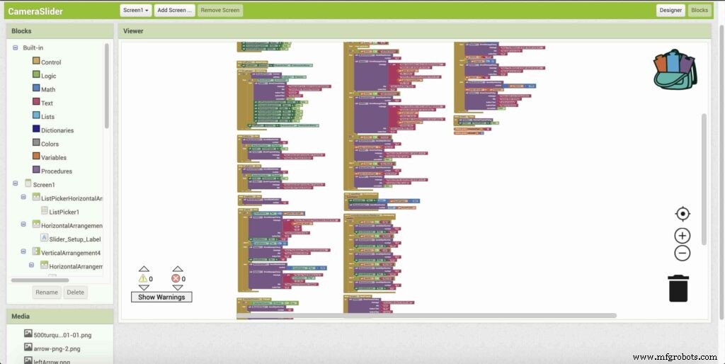
To build the mobile app, I used the MIT App inventor tool that allows you to create mobile apps that run on any Android smartphone. The tool is pretty simple since you only drag and drop some pre-made code blocks to build the logic of your program, also you use some premade blocks to build the app user interface. You can access the source of the mobile app from the link down below. Feel free to edit and share, it’s open-source. Mobile App Source
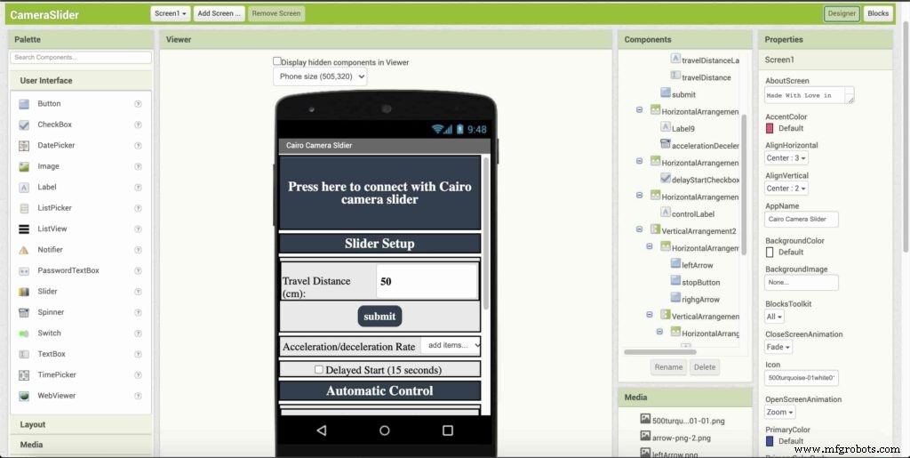
The image down below, a brief explanation for each button function and how it works.
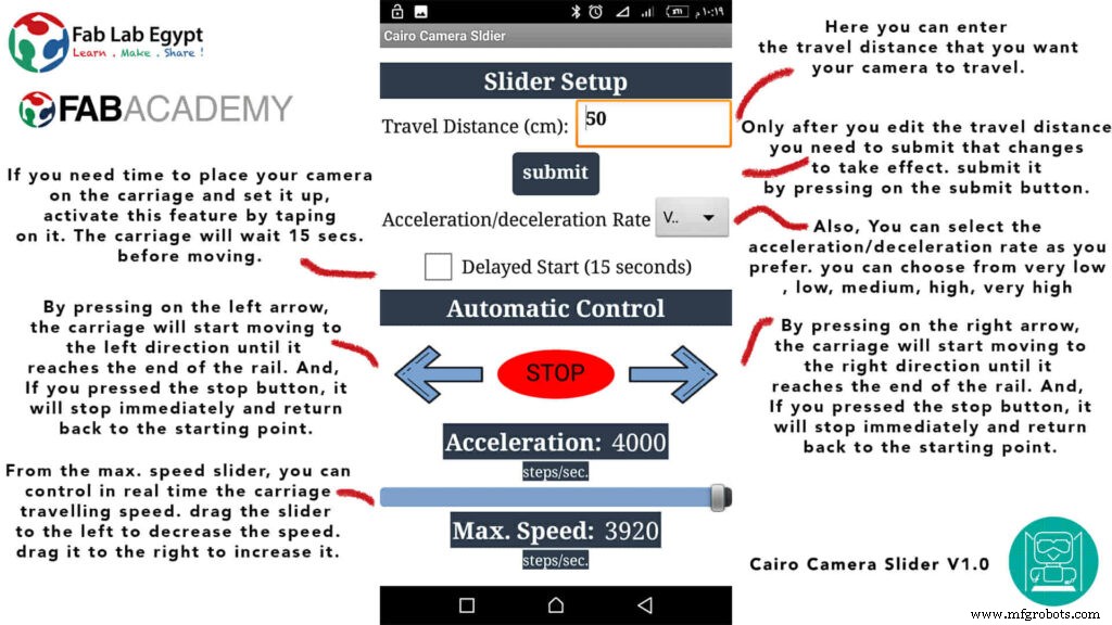
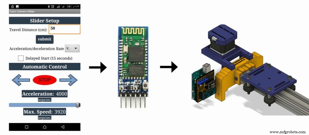
That mobile app will communicate with the Cairo camera slider wirelessly over the Bluetooth communication. So, the next step is to connect a Bluetooth module to the last circuit we built before and upload some lines of code to the Arduino board to be able to establish the communication between the mobile app and the Cairo camera slider.
Wiring Diagram
It’s the time to connect all things together, previously we connected the stepper motor, stepper motor driver, Arduino UNO, and the battery together and tested the circuit and it worked fine. Now, and after building the mobile app, we need to connect the HC-05 Bluetooth module to our circuit.
To make it wireless we will use the HC-05 Bluetooth module which has wide use, it can set as slave or master as well (unlike the HC-06 module which can work only as a slave) which means that you can make a Bluetooth connection between two different Arduino boards. the HC-05 Bluetooth module is an SPP (Serial Port Protocol) module, which means that it communicates with the Arduino board via the Serial communication. You only need to connect the Tx and the Rx pins between the HC-05 module and the Arduino UNO board.
- Tx(Arduino) --> Rx(HC-05)
- Rx(Arduino) --> Tx(HC-05)
- 5V(Arduino) --> VCC(HC-05)
- GNND(Arduino) --> GND(HC-05)
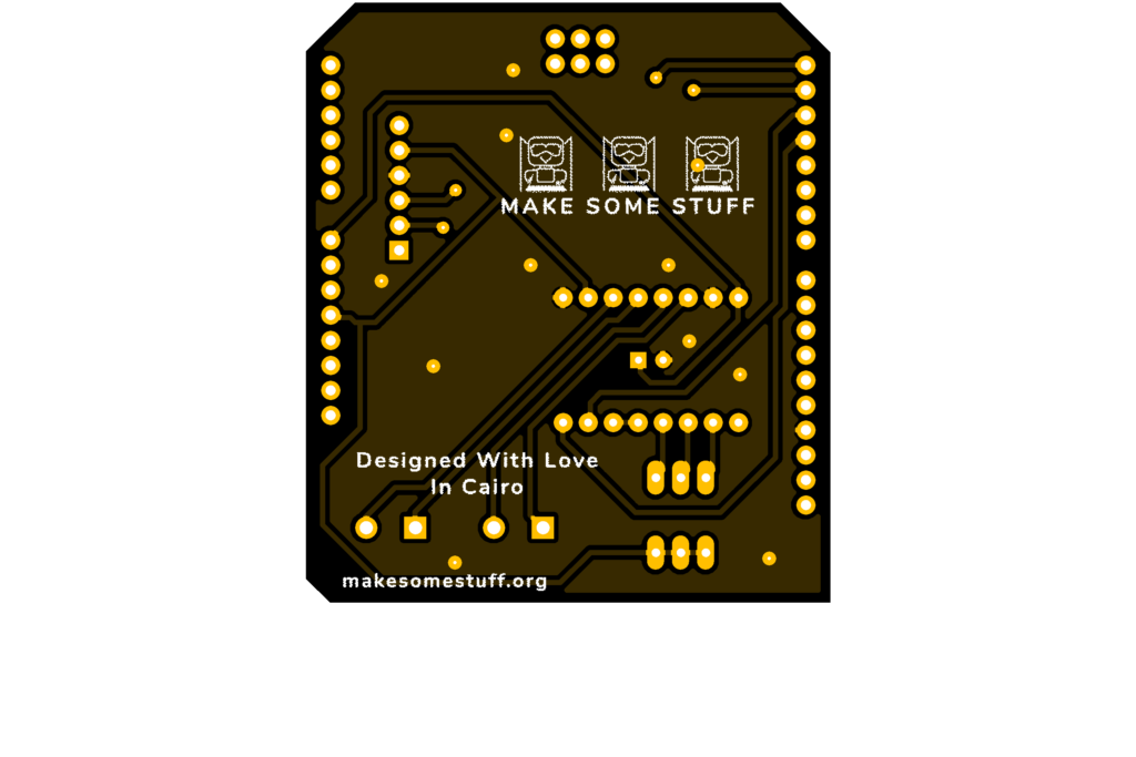
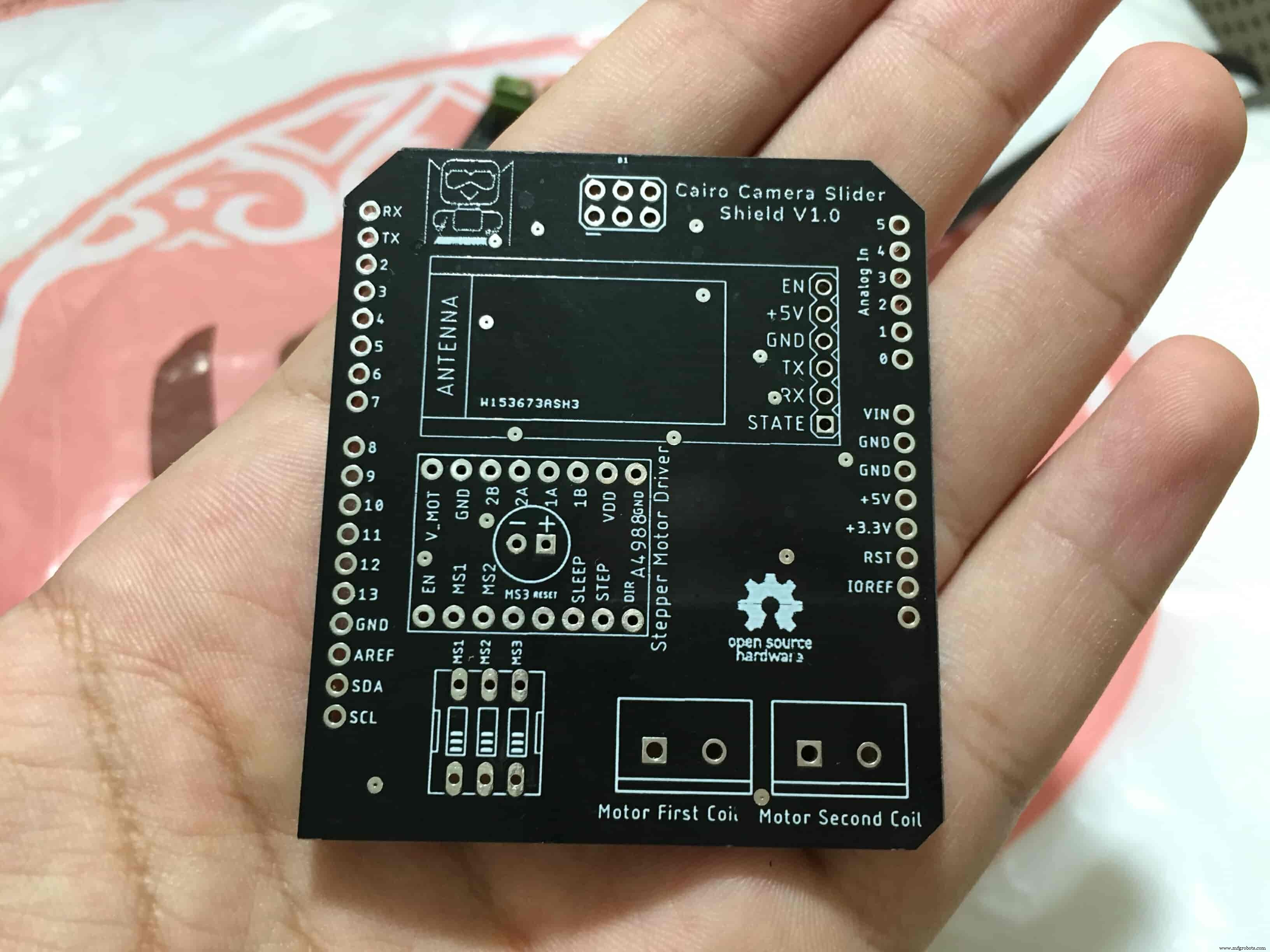
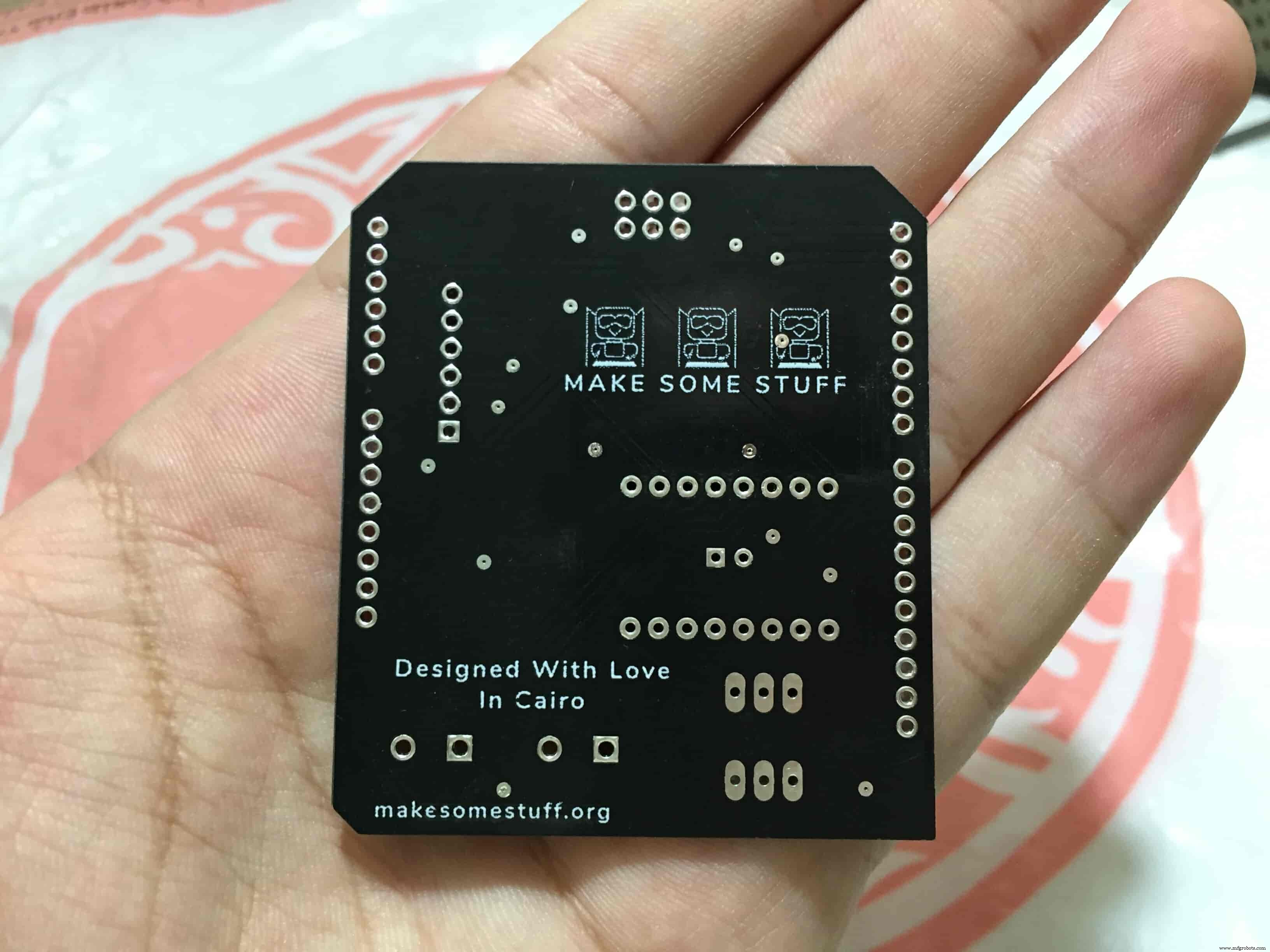
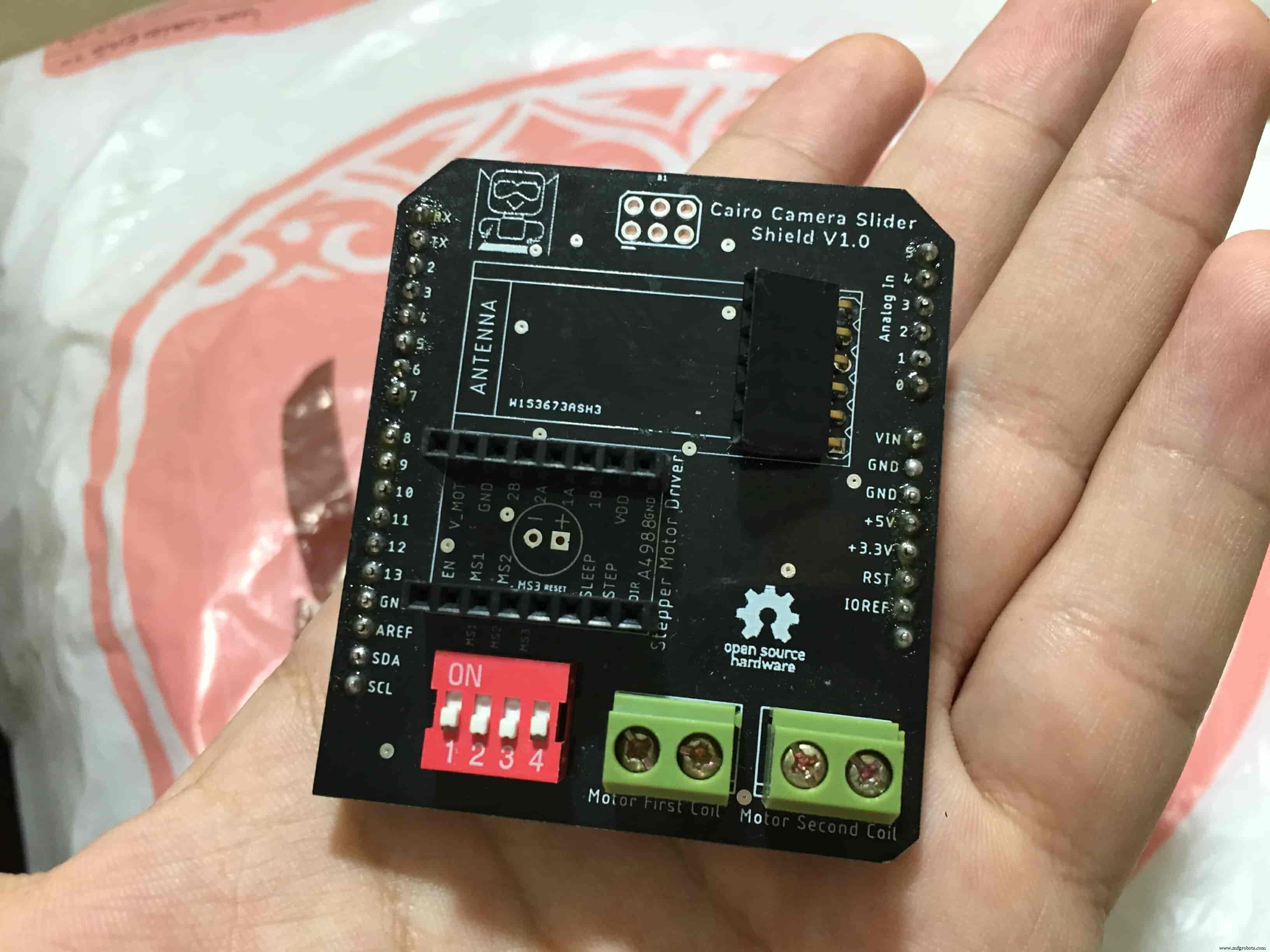
Schematic and PCB Fabrication
¡Hombre! I don’t like breadboarding a big circuit like this. So, I designed a super pretty Arduino UNO shield PCB board that keeps all my components in place without worrying about the jumper wires or even the connections. All you need to do is to place your component on the Arduino shield PCB, insert the HC-05 Bluetooth module, A4988 stepper motor driver, and the battery in their places. and install the shield on top of the Arduino board. that’s it!
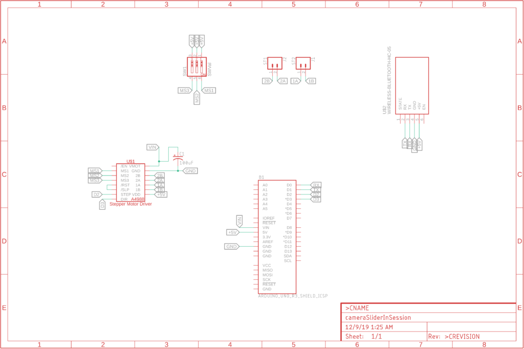
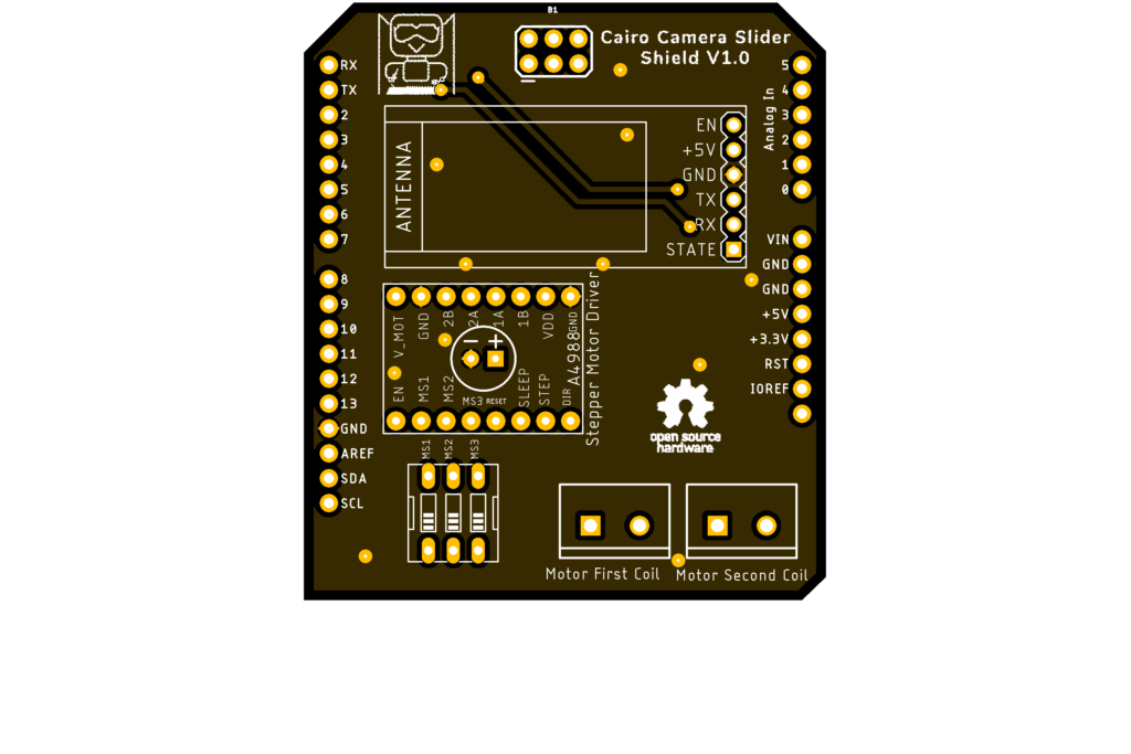
I fabricated my PCB at PCBWay the quality was very good, in a few days the package arrived in Egypt safely. and I paid just 5$ for the fabrication which is amazing. The coolest thing that I was able to check the order fabrication and processing status online on my account panel and track everything happening to my baby board like I was there inside the factory.
you can download the PCB design source files or even ordering the Cairo Camera Slider Arduino Shield PCB from the PCBWay website. PCB Source Files &Ordering

Arduino Code And Bluetooth Communication
/*
 TODO::Update the arduino program to Make the user able to choose the motor driver micro stepping mode. find and equation that helps to automatically adjust the the "steps" variable value.
 TODO::update the mobile app to ask the user on the beginning only about the [homing position(done), microstepping mode].
 TODO::Update the arduino program to make the code only iterates around the "homing position" &"microstepping mode" only once on the void setup() function.

 DATA::left arrow button sends --> 1.
 DATA::right arrow button sends --> 2.
 DATA::stop button sends --> 3.

 DATA::rail length (1cm - 1000cm) --> (201 - 1200).

 DATA::motor acceleration spinner Very High --> 14.
 DATA::motor acceleration spinner High --> 11
 DATA::motor acceleration spinner Medium --> 12
 DATA::motor acceleration spinner Low --> 13
 DATA::motor acceleration spinner Very Low --> 15

 DATA::motor speed slider (1 step/sec. - 4000 step/sec.) --> (5001 - 9000).

 DATA::delay start checkbox is true --> 7.
 DATA::delay start checkbox is false --> 8.

 DATA::left end homing --> 16.
 DATA::right end homing --> 17.

 DATA::Smooth movement Type --> 18.
 DATA::Very Smooth movement Type --> 19.

 1301 --> 2300
*/

#include
#include

#define stepPin 2
#define dirPin 3

bool homingPositionFlag =false;
int startupSetupFlag =0;
bool delayedStart =false;

int incomingData =0;
int movementDistance =50;
long steps =0; //50cm rail by default @1/8 microstepping.
int microStepResolution =0; //4 or 16
long railLength =0;
int sliderSpeed =10;

AccelStepper stepper(AccelStepper::DRIVER, stepPin, dirPin); //create an object. the pin "2" is the step pin, "3" is the direction pin.

void setup() {
 pinMode(stepPin, OUTPUT);
 pinMode(dirPin, OUTPUT);
 Serial.begin(9600);

 stepper.setMaxSpeed(10.00); //The fastest motor speed that can be reliably supported is about 4000 steps per second at a clock frequency of 16 MHz on Arduino such as Uno
 stepper.setAcceleration(500.00); //1600 (40%) (Medium Acceleration rate)

 while (startupSetupFlag <3) {
 if (Serial.available()> 1) {
 unsigned int dataOne =Serial.read();
 unsigned int dataOne1 =Serial.read();
 unsigned int incomingData =(dataOne1 * 256) + dataOne;

 //**************************************************************Motor Homing Part**************************************************
 if (incomingData ==16) { //left end homing position.
 stepper.setCurrentPosition(steps);
 homingPositionFlag =false;
 startupSetupFlag++;
 } else if (incomingData ==17) { //right end homing position.
 stepper.setCurrentPosition(-(steps));
 homingPositionFlag =true;
 startupSetupFlag++;
 }
 //**************************************************************microstep resolution Part**************************************************
 if (incomingData ==18) {
 microStepResolution =4; //50cm rail length @1/4 microstep resolution.
 startupSetupFlag++;
 } else if (incomingData ==19) {
 microStepResolution =16; //50cm rail length @1/16 microstep resolution.
 startupSetupFlag++;
 }

 if (incomingData>=1301 &&incomingData <=2300) {
 railLength =incomingData - 1300; //from raw data to cm.
 if (microStepResolution ==4) {
 steps =((6100L * railLength) / 50L);
 startupSetupFlag++;
 }
 else if (microStepResolution ==16) {
 steps =((25000L * railLength) / 50L);
 startupSetupFlag++;
 }
 }
 }
 //Serial.println(startupSetupFlag);
 }
 /*
 * *********** *********** **********For Debugging Purposes* *********** *********** **********
 Serial.print("rail length:");
 Serial.print(railLength);
 Serial.print(" number of steps:");
 Serial.print(steps);
 Serial.print(" Homing position:");
 Serial.print(stepper.currentPosition());
 Serial.print(" microstep resolution:");
 Serial.println(microStepResolution);*/
}

void loop() {

 if (Serial.available()> 1) {

 unsigned int dataOne =Serial.read();
 unsigned int dataOne1 =Serial.read();
 unsigned int incomingData =(dataOne1 * 256) + dataOne;
 //Serial.print("raw data:");
 //Serial.println(incomingData);

 //**************************************************************Motor Control Part**************************************************
 if (incomingData ==1 &&stepper.isRunning() ==false &&stepper.currentPosition() !=6050 &&homingPositionFlag ==true) {
 if (delayedStart ==true) { //use millis to delay 15 seconds.
 delay(15000); //wait 15 seconds.
 }
 stepper.setCurrentPosition(0);
 stepper.moveTo(steps); //from end to end (@ 1/4 step).
 homingPositionFlag =false;

 /*Serial.print("rail length:");
 Serial.print(railLength);
 Serial.print(" number of steps:");
 Serial.print(steps);
 Serial.print(" Homing position:");
 Serial.print(stepper.currentPosition());
 Serial.print(" microstep resolution:");
 Serial.println(microStepResolution);*/
 }

 else if (incomingData ==2 &&stepper.isRunning() ==false &&stepper.currentPosition() !=-6050 &&homingPositionFlag ==false) {
 if (delayedStart ==true) { //use millis to delay 15 seconds.
 delay(15000); //wait 15 seconds.
 }
 stepper.setCurrentPosition(0);
 stepper.moveTo(-(steps)); //from end to end (@ 1/4 step).
 homingPositionFlag =true;

 /*Serial.print("rail length:");
 Serial.print(railLength);
 Serial.print(" number of steps:");
 Serial.print(steps);
 Serial.print(" Homing position:");
 Serial.print(stepper.currentPosition());
 Serial.print(" microstep resolution:");
 Serial.println(microStepResolution);*/
 }

 else if (incomingData ==3 &&stepper.isRunning() ==true) {
 homing();
 }

 //**************************************************************Set Max. Speed Part**************************************************
 else if (incomingData>=5001 &&incomingData <=9000) {
 sliderSpeed =incomingData - 5000;
 stepper.setMaxSpeed(sliderSpeed);
 }

 //**************************************************************Set Delayed Start Part**************************************************
 else if (incomingData ==7) { //delayed start (15 seconds) is checked "true"
 delayedStart =true;
 }
 else if (incomingData ==8) { //delayed start (15 seconds) is not checked "false"
 delayedStart =false;
 }

 //**************************************************************Set movement distance Part**************************************************
 else if (incomingData>=201 &&incomingData <=1200) { //convertin from rail length into number of steps. (upto 10 meters)
 movementDistance =incomingData - 200; //from raw data to cm.
 if (microStepResolution ==4) {
 steps =((6100L * movementDistance) / 50L);
 }
 else if (microStepResolution ==16) {
 steps =((25000L * movementDistance) / 50L);
 }
 /*Serial.print("rail length:");
 Serial.print(movementDistance);
 Serial.print(" number of steps:");
 Serial.println(steps);*/
 }

 //**************************************************************Set Acceleration Part**************************************************
 else if (incomingData ==11 &&stepper.isRunning() ==false) { //HIGH
 stepper.setAcceleration(3000);
 }

 else if (incomingData ==12 &&stepper.isRunning() ==false) { //Medium
 stepper.setAcceleration(1000);
 }

 else if (incomingData ==13 &&stepper.isRunning() ==false) { //Low
 stepper.setAcceleration(500);
 }

 else if (incomingData ==14 &&stepper.isRunning() ==false) { //Very High
 stepper.setAcceleration(4000);
 }

 else if (incomingData ==15 &&stepper.isRunning() ==false) { //Very Low
 stepper.setAcceleration(10);
 }
 }
 stepper.run();
}

void homing() {
 if (stepper.currentPosition()> 0) {
 homingPositionFlag =true;
 } else {
 homingPositionFlag =false;
 }
 stepper.moveTo(0);
}
Code Logic
We’re using the amazing AccelStepper Arduino library that provides an object-oriented interface for 2, 3, 4 pins stepper motors to control it’s movement precisely.
#define stepPin 2
#define dirPin 3
bool homingPositionFlag =false;
int startupSetupFlag =0;
bool delayedStart =false;
int incomingData =0;
int movementDistance =50;
long steps =0; //50cm rail by default @1/8 microstepping.
int microStepResolution =0; //4 or 16
long railLength =0;
int sliderSpeed =10;
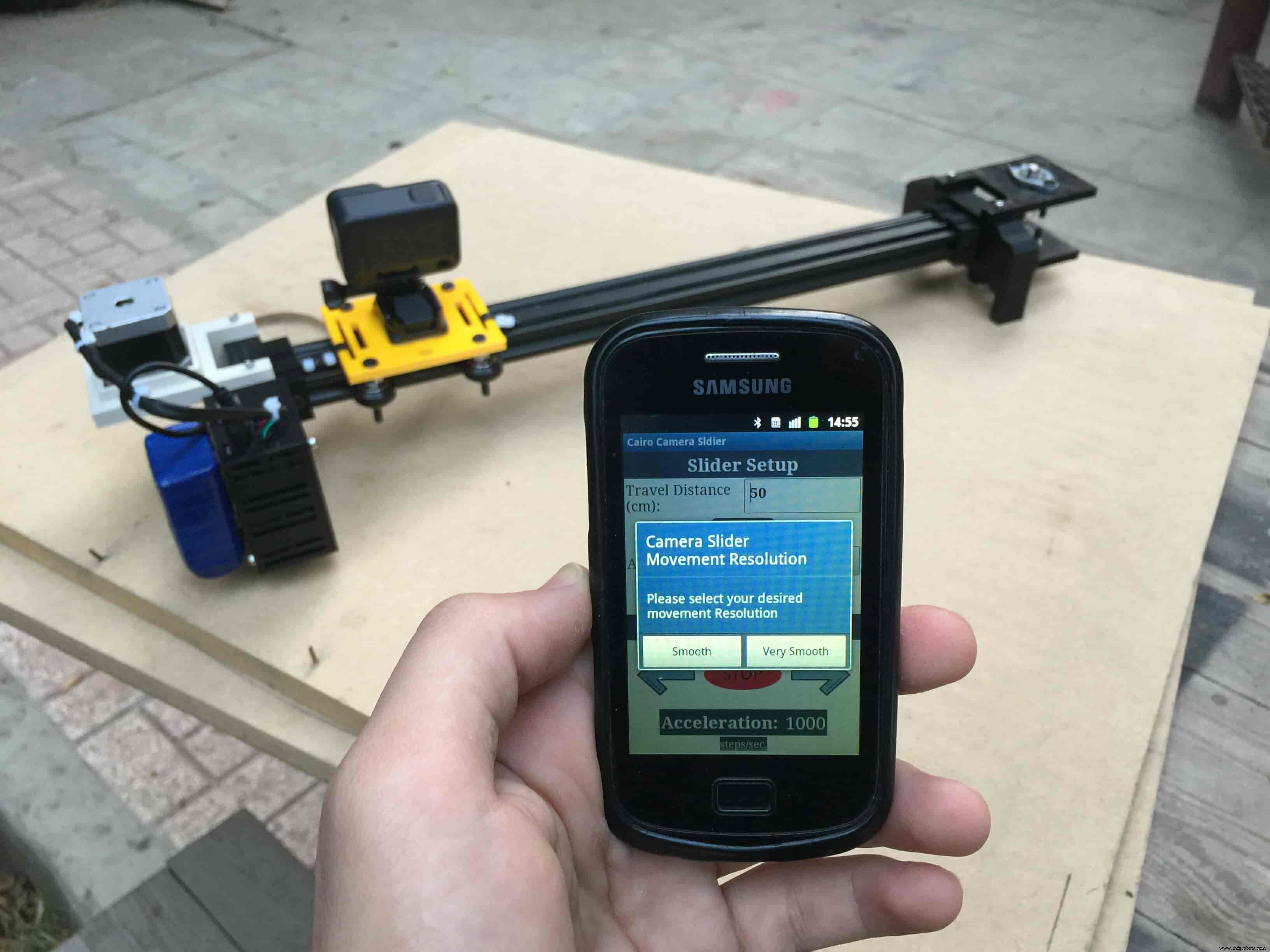
AccelStepper stepper(AccelStepper::DRIVER, stepPin, dirPin); //create an object. the pin "2" is the step pin, "3" is the direction pin. when you open the mobile app and get connected to the Cairo camera slider it will ask you about the micro-stepping mode that you set the A4988 motor driver to work at. it’s very important to choose the correct micro-stepping mode. The Cairo camera slider only supports the 1/4 and 1/16 micro-step resolution. If you chose a wrong micro-step mode it will affect the distance calculations causing the camera carriage to hit the slider limits. So, be careful!
- 1/4 --> Smooth.
- 1/16 --> Very Smooth.

//**************************************************************microstep resolution Part**************************************************
if (incomingData ==18) {
 microStepResolution =4; //50cm rail length @1/4 microstep resolution.
 startupSetupFlag++;

} else if (incomingData ==19) {
 microStepResolution =16; //50cm rail length @1/16 microstep resolution.
 startupSetupFlag++;
}
It sets the camera slider homing if it’s left or right side homing. the homing position, once you click on right or left side homing a specific piece of data will get sent from the mobile app to the Arduino board according to the homing position that you have chosen.

void setup() {
pinMode(stepPin, OUTPUT);
pinMode(dirPin, OUTPUT);
Serial.begin(9600);
stepper.setMaxSpeed(10.00); //The fastest motor speed that can be reliably supported is about 4000 steps per second at a clock frequency of 16 MHz on Arduino such as Uno
stepper.setAcceleration(500.00); //1600 (40%) (Medium Acceleration rate)
while (startupSetupFlag <3) {
if (Serial.available()> 1) {
unsigned int dataOne =Serial.read();
unsigned int dataOne1 =Serial.read();
unsigned int incomingData =(dataOne1 * 256) + dataOne;
//**************************************************************Motor Homing Part**************************************************
if (incomingData ==16) { //left end homing position.
stepper.setCurrentPosition(steps);
homingPositionFlag =false;
startupSetupFlag++;
}
else if (incomingData ==17) { //right end homing position.
stepper.setCurrentPosition(-(steps));
homingPositionFlag =true;
startupSetupFlag++;
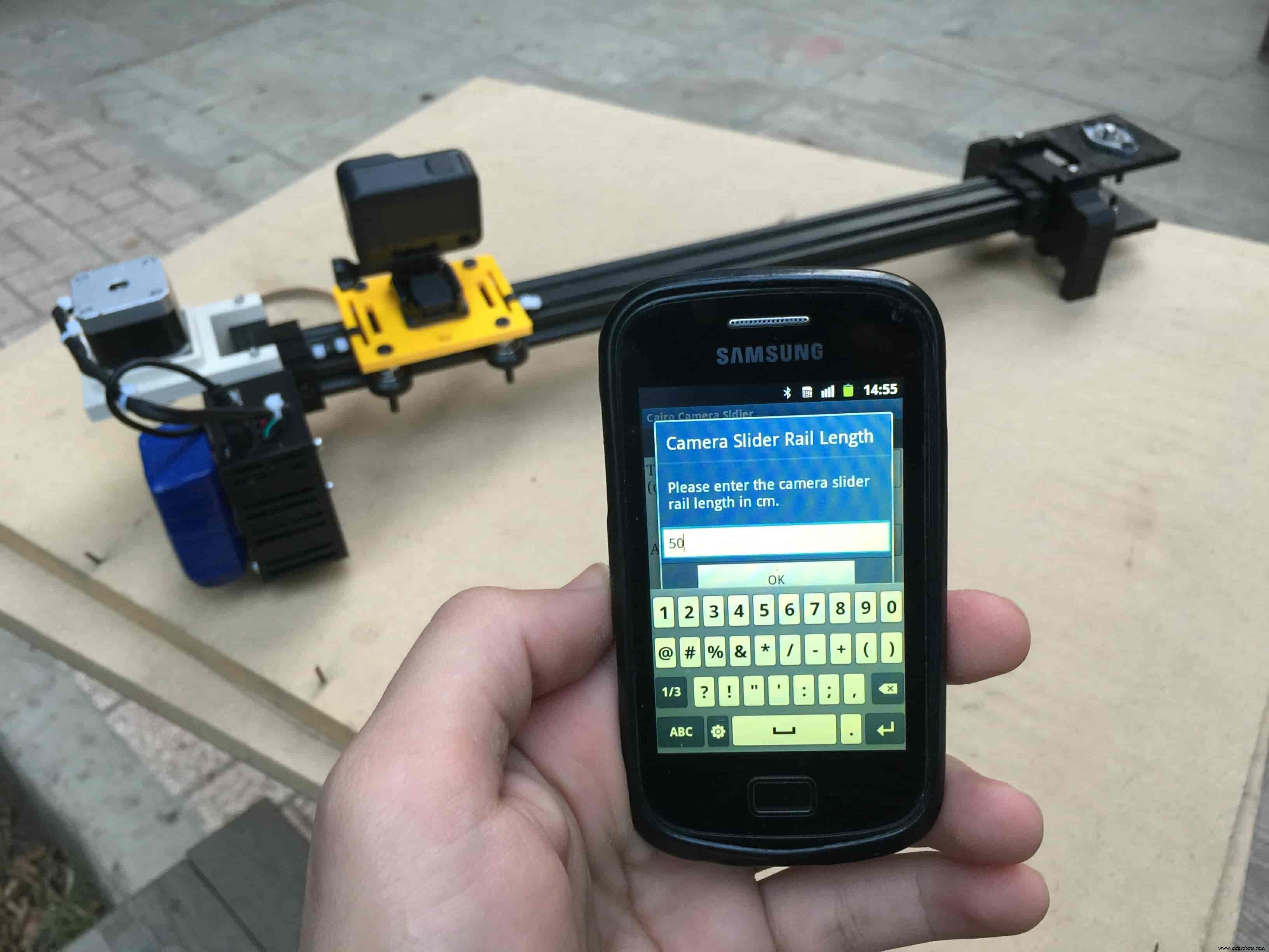
} now it sets how many steps should the stepper motor moves without hitting the camera carriage with the camera slider right or left legs. it reads and saves the rail length according to the value that the user enters in the mobile app. So, depending on the micro-step resolution that the user selected before, and the rail length I can calculate the number of steps that the motor should rotate to reach the limits of the slider rail without hitting the right or left legs.

if (incomingData>=1301 &&incomingData <=2300) {
 railLength =incomingData - 1300; //from raw data to cm.
 if (microStepResolution ==4) {
 steps =((6100L * railLength) / 50L);
 startupSetupFlag++;
 }
 else if (microStepResolution ==16) {
 steps =((25000L * railLength) / 50L);
 startupSetupFlag++;
 }
 }
 }
 //Serial.println(startupSetupFlag);
 }
inside the loop function, it reads the mobile app incoming data and according to these data it takes different actions, like moving the stepper motor clockwise, moving anti-clockwise, stop and return back to the starting point, and changing the traveling speed, so on…
void loop() {

 if (Serial.available()> 1) {

 unsigned int dataOne =Serial.read();
 unsigned int dataOne1 =Serial.read();
 unsigned int incomingData =(dataOne1 * 256) + dataOne;
 //Serial.print("raw data:");
 //Serial.println(incomingData);

 //**************************************************************Motor Control Part**************************************************
 if (incomingData ==1 &&stepper.isRunning() ==false &&stepper.currentPosition() !=6050 &&homingPositionFlag ==true) {
 if (delayedStart ==true) { //use millis to delay 15 seconds.
 delay(15000); //wait 15 seconds.
 }
 stepper.setCurrentPosition(0);
 stepper.moveTo(steps); //from end to end (@ 1/4 step).
 homingPositionFlag =false;

 /*Serial.print("rail length:");
 Serial.print(railLength);
 Serial.print(" number of steps:");
 Serial.print(steps);
 Serial.print(" Homing position:");
 Serial.print(stepper.currentPosition());
 Serial.print(" microstep resolution:");
 Serial.println(microStepResolution);*/
 }

 else if (incomingData ==2 &&stepper.isRunning() ==false &&stepper.currentPosition() !=-6050 &&homingPositionFlag ==false) {
 if (delayedStart ==true) { //use millis to delay 15 seconds.
 delay(15000); //wait 15 seconds.
 }
 stepper.setCurrentPosition(0);
 stepper.moveTo(-(steps)); //from end to end (@ 1/4 step).
 homingPositionFlag =true;

 /*Serial.print("rail length:");
 Serial.print(railLength);
 Serial.print(" number of steps:");
 Serial.print(steps);
 Serial.print(" Homing position:");
 Serial.print(stepper.currentPosition());
 Serial.print(" microstep resolution:");
 Serial.println(microStepResolution);*/
 }

 else if (incomingData ==3 &&stepper.isRunning() ==true) {
 homing();
 }

 //**************************************************************Set Max. Speed Part**************************************************
 else if (incomingData>=5001 &&incomingData <=9000) {
 sliderSpeed =incomingData - 5000;
 stepper.setMaxSpeed(sliderSpeed);
 }

 //**************************************************************Set Delayed Start Part**************************************************
 else if (incomingData ==7) { //delayed start (15 seconds) is checked "true"
 delayedStart =true;
 }
 else if (incomingData ==8) { //delayed start (15 seconds) is not checked "false"
 delayedStart =false;
 }

 //**************************************************************Set movement distance Part**************************************************
 else if (incomingData>=201 &&incomingData <=1200) { //convertin from rail length into number of steps. (upto 10 meters)
 movementDistance =incomingData - 200; //from raw data to cm.
 if (microStepResolution ==4) {
 steps =((6100L * movementDistance) / 50L);
 }
 else if (microStepResolution ==16) {
 steps =((25000L * movementDistance) / 50L);
 }
 /*Serial.print("rail length:");
 Serial.print(movementDistance);
 Serial.print(" number of steps:");
 Serial.println(steps);*/
 }

 //**************************************************************Set Acceleration Part**************************************************
 else if (incomingData ==11 &&stepper.isRunning() ==false) { //HIGH
 stepper.setAcceleration(3000);
 }

 else if (incomingData ==12 &&stepper.isRunning() ==false) { //Medium
 stepper.setAcceleration(1000);
 }

 else if (incomingData ==13 &&stepper.isRunning() ==false) { //Low
 stepper.setAcceleration(500);
 }

 else if (incomingData ==14 &&stepper.isRunning() ==false) { //Very High
 stepper.setAcceleration(4000);
 }

 else if (incomingData ==15 &&stepper.isRunning() ==false) { //Very Low
 stepper.setAcceleration(10);
 }
 }
 stepper.run();
}

void homing() {
 if (stepper.currentPosition()> 0) {
 homingPositionFlag =true;
 } else {
 homingPositionFlag =false;
 }
 stepper.moveTo(0);
}
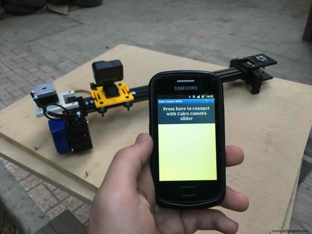
Cairo Camera Slider User Guide &troubleshooting
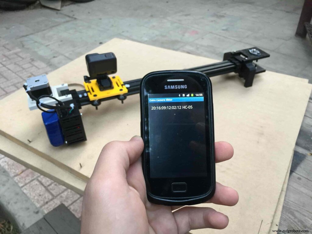
After connecting the 12V power source to the Arduino UNO board that distributes power to the Cairo camera slider Arduino shield as well, turn on the Bluetooth on your mobile, search for new devices, pair with the HC-05 device, and open the mobile app then press on the “Press here to connect with Cairo camera slider” button. It will show up the menu of the paired Bluetooth devices, select the HC-05 Bluetooth device.
After connecting successfully with the Control board, the mobile app will ask you some questions to set up some parameters. First question will ask you about the micro-step resolution of the stepper motor driver if it’s smooth(1/4 micro-step), or very smooth(1/16 micro-step). select the mode According to the micro-stepping resolution mode that you set the A4988 driver at. If you selected a wrong mode The Cairo camera slider will not work correctly.
Then, it will ask you about the aluminum rail length that you are using in your camera slider. Enter the distance in CM. in my case I’m using a 50cm rail length.
Lastly, it will ask you about the camera carriage homing position, It’s very important to place the camera carriage on one of the two rail ends, the right end or the left end. In my case, the camera carriage is on the left end. So, I selected the left end homing.
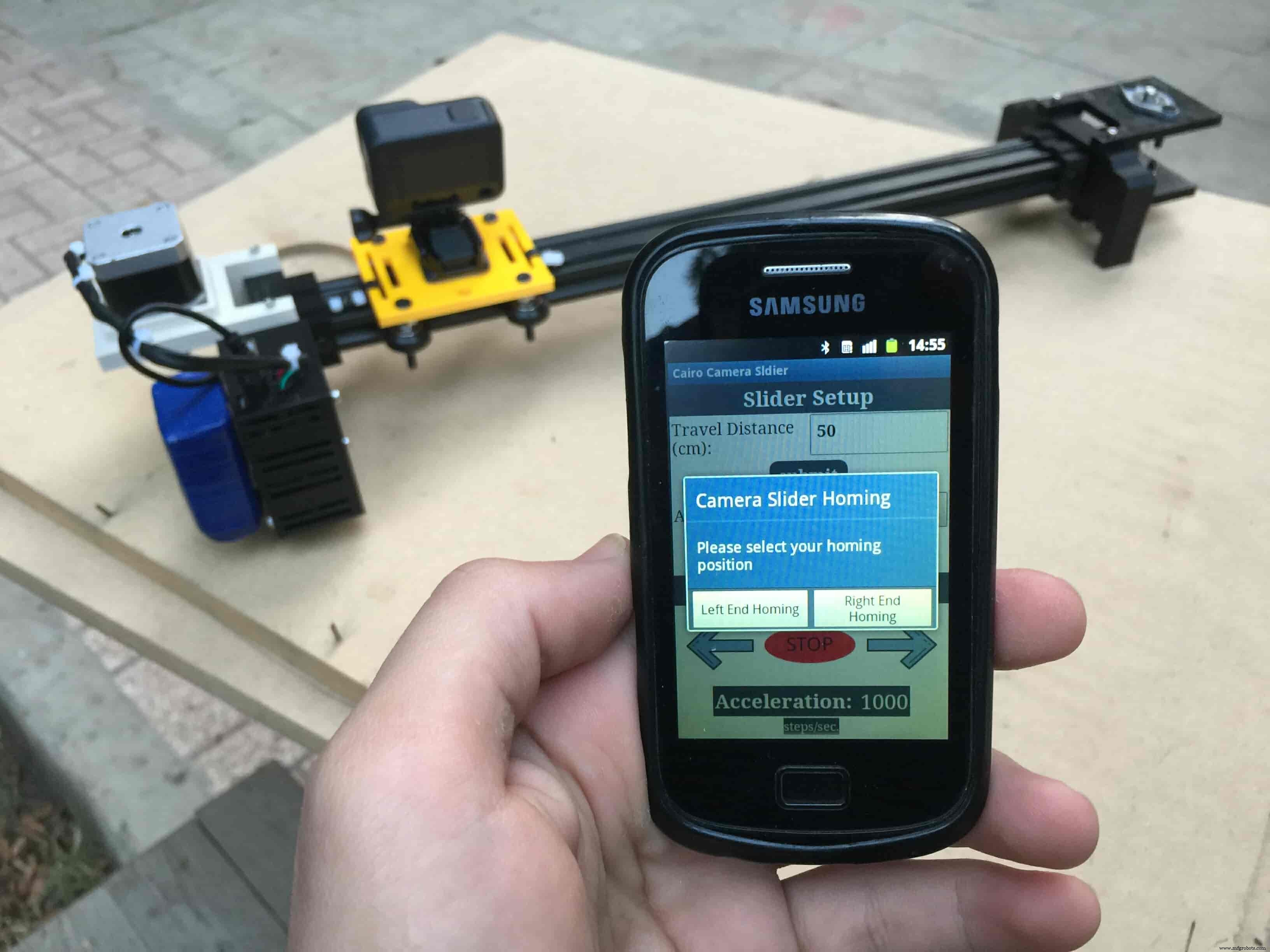
If you started the Cairo camera slider and the camera carriage is on the middle of the rail or not on one of the two rail ends it will cause the carriage to hit the limits when it moves.
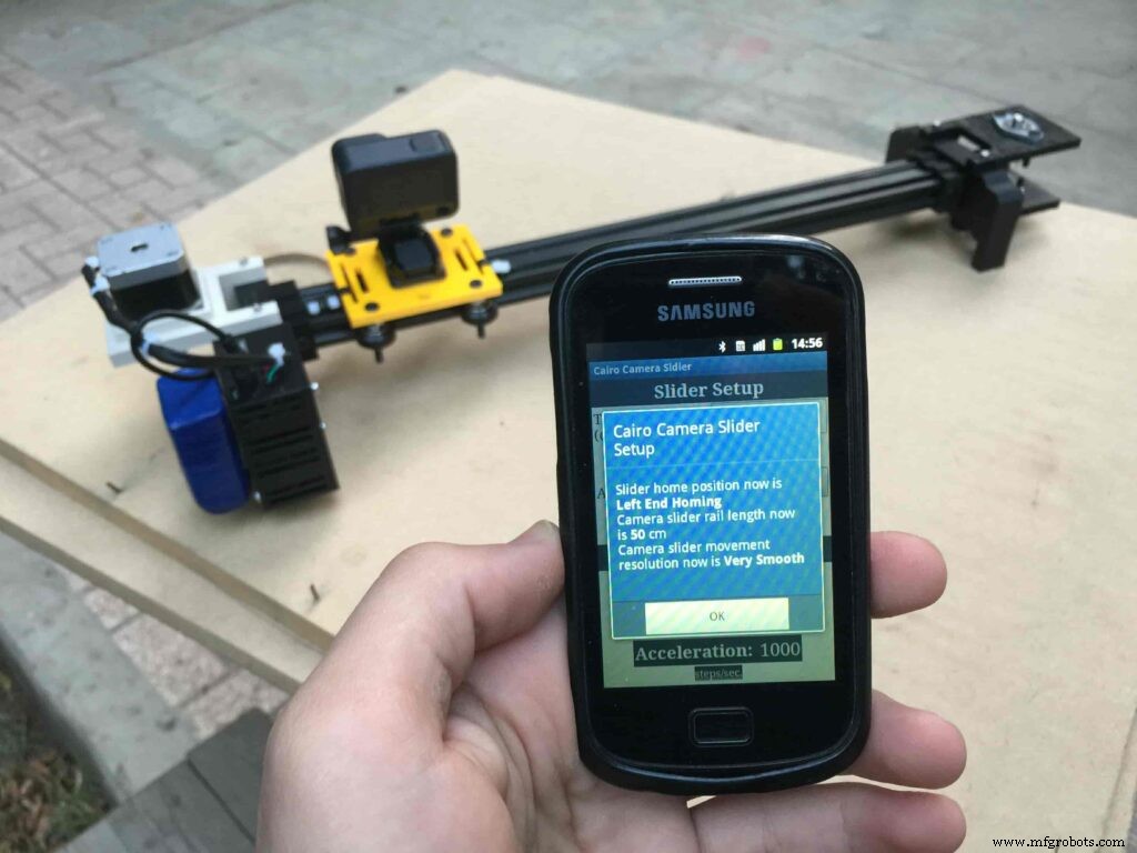
After you finish the set-up process, It will show you the parameters that you have set. And once you click OK, you will be ready to play around with your lovely Cairo camera slider.
Cairo Camera Slider In-Action
Code
- Cairo Camera Slider Final Code
Cairo Camera Slider Final CodeArduino
/* TODO::Update the arduino program to Make the user able to choose the motor driver micro stepping mode. find and equation that helps to automatically adjust the the "steps" variable value. TODO::update the mobile app to ask the user on the beginning only about the [homing position(done), microstepping mode]. TODO::Update the arduino program to make the code only iterates around the "homing position" &"microstepping mode" only once on the void setup() function. DATA::left arrow button sends --> 1. DATA::right arrow button sends --> 2. DATA::stop button sends --> 3. DATA::rail length (1cm - 1000cm) --> (201 - 1200). DATA::motor acceleration spinner Very High --> 14. DATA::motor acceleration spinner High --> 11 DATA::motor acceleration spinner Medium --> 12 DATA::motor acceleration spinner Low --> 13 DATA::motor acceleration spinner Very Low --> 15 DATA::motor speed slider (1 step/sec. - 4000 step/sec.) --> (5001 - 9000). DATA::delay start checkbox is true --> 7. DATA::delay start checkbox is false --> 8. DATA::left end homing --> 16. DATA::right end homing --> 17. DATA::Smooth movement Type --> 18. DATA::Very Smooth movement Type --> 19. 1301 --> 2300*/#include#include #define stepPin 2#define dirPin 3bool homingPositionFlag =false;int startupSetupFlag =0;bool delayedStart =false;int incomingData =0;int movementDistance =50;long steps =0; //50cm rail by default @1/8 microstepping.int microStepResolution =0; //4 or 16long railLength =0;int sliderSpeed =10;AccelStepper stepper(AccelStepper::DRIVER, stepPin, dirPin); //create an object. the pin "2" is the step pin, "3" is the direction pin.void setup() { pinMode(stepPin, OUTPUT); pinMode(dirPin, OUTPUT); Serial.begin(9600); stepper.setMaxSpeed(10.00); //The fastest motor speed that can be reliably supported is about 4000 steps per second at a clock frequency of 16 MHz on Arduino such as Uno stepper.setAcceleration(500.00); //1600 (40%) (Medium Acceleration rate) while (startupSetupFlag <3) { if (Serial.available()> 1) { unsigned int dataOne =Serial.read(); unsigned int dataOne1 =Serial.read(); unsigned int incomingData =(dataOne1 * 256) + dataOne; //**************************************************************Motor Homing Part************************************************** if (incomingData ==16) { //left end homing position. stepper.setCurrentPosition(steps); homingPositionFlag =false; startupSetupFlag++; } else if (incomingData ==17) { //right end homing position. stepper.setCurrentPosition(-(steps)); homingPositionFlag =true; startupSetupFlag++; } //**************************************************************microstep resolution Part************************************************** if (incomingData ==18) { microStepResolution =4; //50cm rail length @1/4 microstep resolution. startupSetupFlag++; } else if (incomingData ==19) { microStepResolution =16; //50cm rail length @1/16 microstep resolution. startupSetupFlag++; } if (incomingData>=1301 &&incomingData <=2300) { railLength =incomingData - 1300; //from raw data to cm. if (microStepResolution ==4) { steps =((6100L * railLength) / 50L); startupSetupFlag++; } else if (microStepResolution ==16) { steps =((25000L * railLength) / 50L); startupSetupFlag++; } } } //Serial.println(startupSetupFlag); } /* * *********** *********** **********For Debugging Purposes* *********** *********** ********** Serial.print("rail length:"); Serial.print(railLength); Serial.print(" number of steps:"); Serial.print(steps); Serial.print(" Homing position:"); Serial.print(stepper.currentPosition()); Serial.print(" microstep resolution:"); Serial.println(microStepResolution);*/}void loop() { if (Serial.available()> 1) { unsigned int dataOne =Serial.read(); unsigned int dataOne1 =Serial.read(); unsigned int incomingData =(dataOne1 * 256) + dataOne; //Serial.print("raw data:"); //Serial.println(incomingData); //**************************************************************Motor Control Part************************************************** if (incomingData ==1 &&stepper.isRunning() ==false &&stepper.currentPosition() !=6050 &&homingPositionFlag ==true) { if (delayedStart ==true) { //use millis to delay 15 seconds. delay(15000); //wait 15 seconds. } stepper.setCurrentPosition(0); stepper.moveTo(steps); //from end to end (@ 1/4 step). homingPositionFlag =false; /*Serial.print("rail length:"); Serial.print(railLength); Serial.print(" number of steps:"); Serial.print(steps); Serial.print(" Homing position:"); Serial.print(stepper.currentPosition()); Serial.print(" microstep resolution:"); Serial.println(microStepResolution);*/ } else if (incomingData ==2 &&stepper.isRunning() ==false &&stepper.currentPosition() !=-6050 &&homingPositionFlag ==false) { if (delayedStart ==true) { //use millis to delay 15 seconds. delay(15000); //wait 15 seconds. } stepper.setCurrentPosition(0); stepper.moveTo(-(steps)); //from end to end (@ 1/4 step). homingPositionFlag =true; /*Serial.print("rail length:"); Serial.print(railLength); Serial.print(" number of steps:"); Serial.print(steps); Serial.print(" Homing position:"); Serial.print(stepper.currentPosition()); Serial.print(" microstep resolution:"); Serial.println(microStepResolution);*/ } else if (incomingData ==3 &&stepper.isRunning() ==true) { homing(); } //**************************************************************Set Max. Speed Part************************************************** else if (incomingData>=5001 &&incomingData <=9000) { sliderSpeed =incomingData - 5000; stepper.setMaxSpeed(sliderSpeed); } //**************************************************************Set Delayed Start Part************************************************** else if (incomingData ==7) { //delayed start (15 seconds) is checked "true" delayedStart =true; } else if (incomingData ==8) { //delayed start (15 seconds) is not checked "false" delayedStart =false; } //**************************************************************Set movement distance Part************************************************** else if (incomingData>=201 &&incomingData <=1200) { //convertin from rail length into number of steps. (upto 10 meters) movementDistance =incomingData - 200; //from raw data to cm. if (microStepResolution ==4) { steps =((6100L * movementDistance) / 50L); } else if (microStepResolution ==16) { steps =((25000L * movementDistance) / 50L); } /*Serial.print("rail length:"); Serial.print(movementDistance); Serial.print(" number of steps:"); Serial.println(steps);*/ } //**************************************************************Set Acceleration Part************************************************** else if (incomingData ==11 &&stepper.isRunning() ==false) { //HIGH stepper.setAcceleration(3000); } else if (incomingData ==12 &&stepper.isRunning() ==false) { //Medium stepper.setAcceleration(1000); } else if (incomingData ==13 &&stepper.isRunning() ==false) { //Low stepper.setAcceleration(500); } else if (incomingData ==14 &&stepper.isRunning() ==false) { //Very High stepper.setAcceleration(4000); } else if (incomingData ==15 &&stepper.isRunning() ==false) { //Very Low stepper.setAcceleration(10); } } stepper.run();}void homing() { if (stepper.currentPosition()> 0) { homingPositionFlag =true; } else { homingPositionFlag =false; } stepper.moveTo(0);}
Custom parts and enclosures
Cairo Camera Slider STLs
CAD file on thingiverse.comSchematics

Proceso de manufactura