


Módulo de comunicación inalámbrica de largo alcance Arduino y HC-12
En este tutorial de Arduino, aprenderemos a utilizar el módulo de comunicación serie inalámbrica HC-12, que es capaz de realizar una comunicación inalámbrica de largo alcance entre varias placas Arduino, con distancias de hasta 1,8 km. Puede ver el siguiente video o leer el tutorial escrito a continuación para obtener más detalles.
Para este tutorial hice dos ejemplos básicos que explican cómo conectar el módulo HC-12 y hacer una comunicación básica entre dos Arduinos y un ejemplo adicional donde usando un sensor de acelerómetro en el primer Arduino controlo de forma inalámbrica la posición del paso a paso en el segundo Arduino.
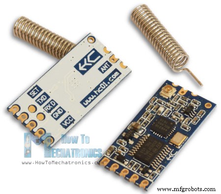
Primero, echemos un vistazo más de cerca al módulo de comunicación de puerto serie inalámbrico HC-12. Aquí hay algunas especificaciones:
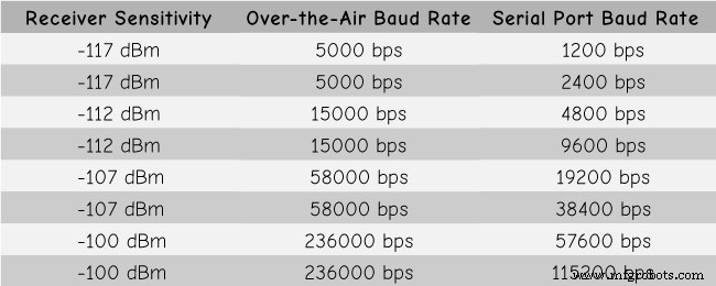
Estos valores en realidad dependen de la velocidad de transmisión en serie y por aire seleccionada, como se ve en la tabla.
El módulo HC-12 tiene un microcontrolador que en realidad no tiene que ser programado por el usuario. Para configurar el módulo simplemente usamos comandos AT, que se pueden enviar desde un Arduino, una PC o cualquier otro microcontrolador usando el puerto serie. Para ingresar al modo de comando AT solo tenemos que configurar el pin "Set" del módulo a un nivel lógico bajo.
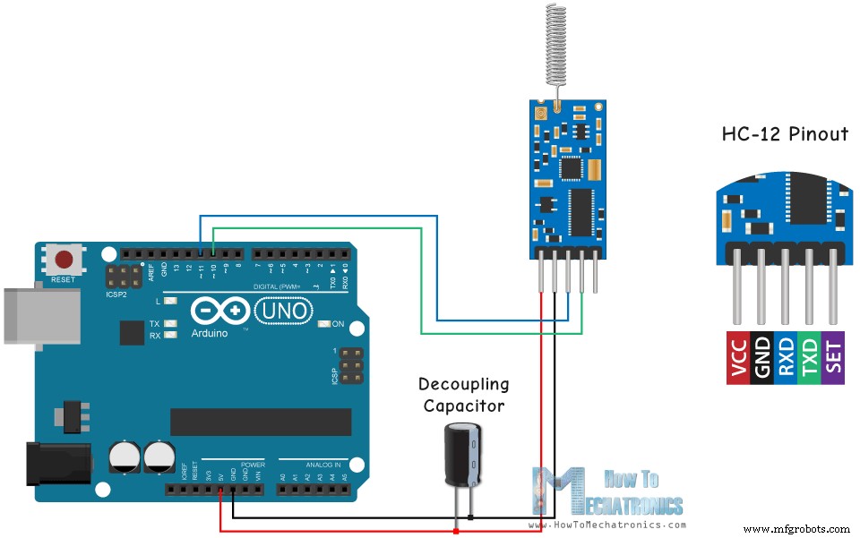
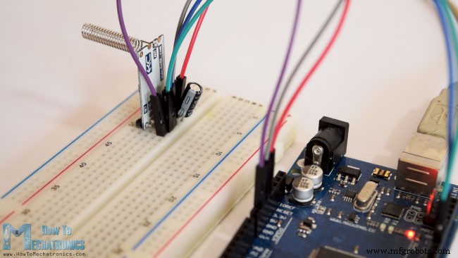
Ahora conectemos el módulo HC-12 al Arduino y hagamos el primer ejemplo. Aquí está el esquema del circuito. La tensión de funcionamiento del módulo es de 3,2 V a 5,5 V y para un trabajo más estable se recomienda utilizar un condensador de desacoplamiento y una fuente de alimentación externa. Sin embargo, utilicé el USB de la PC como fuente de alimentación para los tres ejemplos de este tutorial y no tuve ningún problema.
Conecté el primer módulo a un Arduino UNO y el segundo módulo a un Arduino MEGA, pero por supuesto, puedes usar cualquier placa que quieras.
Puede obtener los componentes necesarios para este tutorial de Arduino desde los siguientes enlaces:
Aquí está el código de Arduino para el primer ejemplo, una comunicación básica entre los dos módulos usando el Monitor Serial.
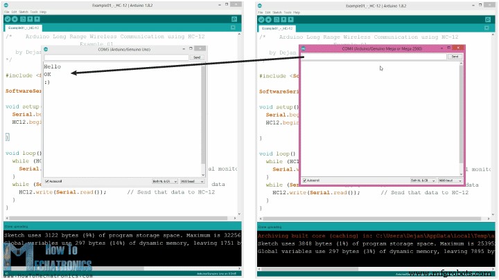
El mismo código se utiliza para ambos Arduinos. Podemos conectar los dos Arduinos en dos computadoras separadas pero también podemos usar una sola computadora.
En ese caso, una vez que conectamos el primer Arduino a la computadora, debemos seleccionar el modelo y el puerto COM y cargar el código al Arduino. Luego conectamos el segundo Arduino y tenemos que volver a iniciar el IDE de Arduino para poder seleccionar el otro puerto COM al que está conectado nuestro segundo Arduino, y luego cargar el mismo código.
Entonces, una vez que tengamos los dos IDE de Arduino en ejecución, podemos iniciar los monitores en serie y probar si la comunicación funciona correctamente. Todo lo que escribamos en el monitor serie se enviará de uno a otro Arduino.
Cómo funciona el código: Entonces, una vez que escribimos algo en el monitor serie y hacemos clic en el botón Enviar, en el primer Arduino, el ciclo while con la función Serial.disponible() se hará realidad y usando la función HC12.write() enviaremos los datos desde el monitor serie al módulo HC-12. Este módulo transferirá los datos de forma inalámbrica al segundo módulo HC-12, por lo que en el segundo Arduino el bucle while con la función HC12.disponible() se hará realidad y utilizando la función Serial.write() los datos se enviarán al monitor de serie.
Podemos usar el mismo código para enviar comandos AT y configurar los parámetros del módulo. Todo lo que tenemos que hacer es conectar el pin "Establecer" del módulo a Tierra o cualquier pin digital del Arduino y establecer el pin en un nivel lógico bajo.
Para probar si hemos ingresado con éxito al modo, en el monitor serial podemos escribir "AT" y debería obtener un mensaje de respuesta "OK". Hay un total de 12 comandos AT, y se usan para cambiar varios parámetros como la velocidad en baudios, el canal, la potencia de transmisión, etc. Por ejemplo, si escribimos "AT+B38400", la velocidad en baudios del módulo se establecerá en 38400.
1. AT - Comando de prueba.
Ejemplo:envíe "AT" al módulo y el módulo devuelve "OK".
2. AT+Bxxxx:cambia la velocidad de transmisión del puerto serie.
Velocidades de transmisión disponibles:1200 bps, 2400 bps, 4800 bps, 9600 bps, 19200 bps, 38400 bps, 57600 bps y 115200 bps. Predeterminado:9600 bps.
Ejemplo:envíe "AT+B38400" al módulo y el módulo devuelve "OK+B19200".
3. AT+Cxxxx:cambia el canal de comunicación inalámbrica, de 001 a 100.
Predeterminado:Canal 001, con frecuencia de trabajo de 433.4MHz. Cada canal siguiente es 400 KHz más alto.
Ejemplo: Si queremos configurar el módulo en el canal 006, debemos enviar el comando "AT+C006" al módulo, y el módulo devolverá "OK+C006". La nueva frecuencia de trabajo será de 435,4 MHz.
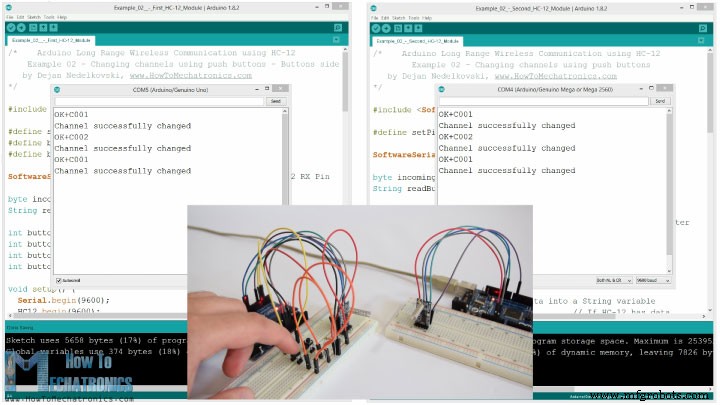
Ahora pasemos al segundo ejemplo. Aquí usaremos dos botones para seleccionar diferentes canales de comunicación y veremos un método diferente para almacenar los datos entrantes.
Nota:Los pines “Set” de ambos módulos HC-12 están conectados a los pines número 6 de los dos Arduinos y los dos botones, en el primer Arduino, a los pines 4 y 3.
Primer código Arduino:
Segundo código Arduino:
Descripción de los códigos:
Entonces, primero debemos definir los pines y configurar el pin "Establecer" en un nivel lógico alto para que el módulo funcione en modo normal y transparente. Con el primer bucle while almacenamos los datos entrantes en una variable de cadena, para que podamos manejarlos mejor.
Los datos entrantes siempre vienen un byte a la vez, así que, por ejemplo, si enviamos la cadena "Test123" desde el segundo Arduino, este ciclo while hará 7 iteraciones. En cada iteración, usando la función HC12.read(), leeremos cada byte o carácter entrante y lo agregaremos a la variable String denominada "readBuffer".
A continuación, veamos cómo podemos cambiar el canal de comunicación usando el primer botón. Entonces, si presionamos el primer botón, usando la función HC12.print(), enviaremos la cadena "AT+C001" al módulo HC-12 o al segundo Arduino.
Cuando esta cadena se reciba en el segundo Arduino, configuraremos el módulo HC-12 en el modo de comando AT y luego escribiremos la misma cadena "AT + C001" que configurará el módulo en el canal de comunicación número uno.
Usamos el siguiente bucle while para imprimir el mensaje de respuesta del módulo HC-12 si el canal se ha cambiado correctamente.
Volviendo al primer Arduino, hacemos el mismo procedimiento de enviar el comando AT al primer módulo HC-12. De la misma manera nosotros, presionando el segundo botón, configuramos el canal de comunicación número dos. Así usando este método podemos seleccionar, en cualquier momento, con qué módulo HC-12 nos comunicaremos.
Al final, la función personalizada checkATCommand() verifica si el mensaje recibido es un comando AT, verificando si la cadena comienza con "AT". Si es así, el módulo ingresa al modo de comando AT y ejecuta el comando.
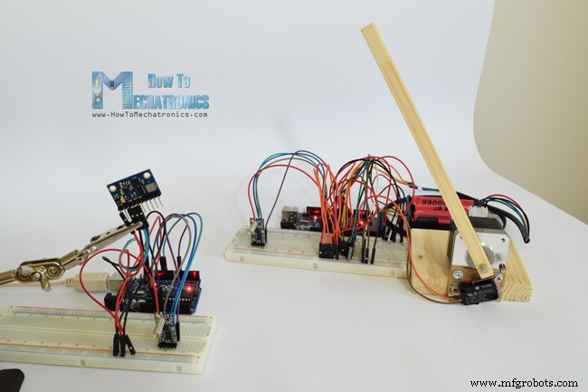
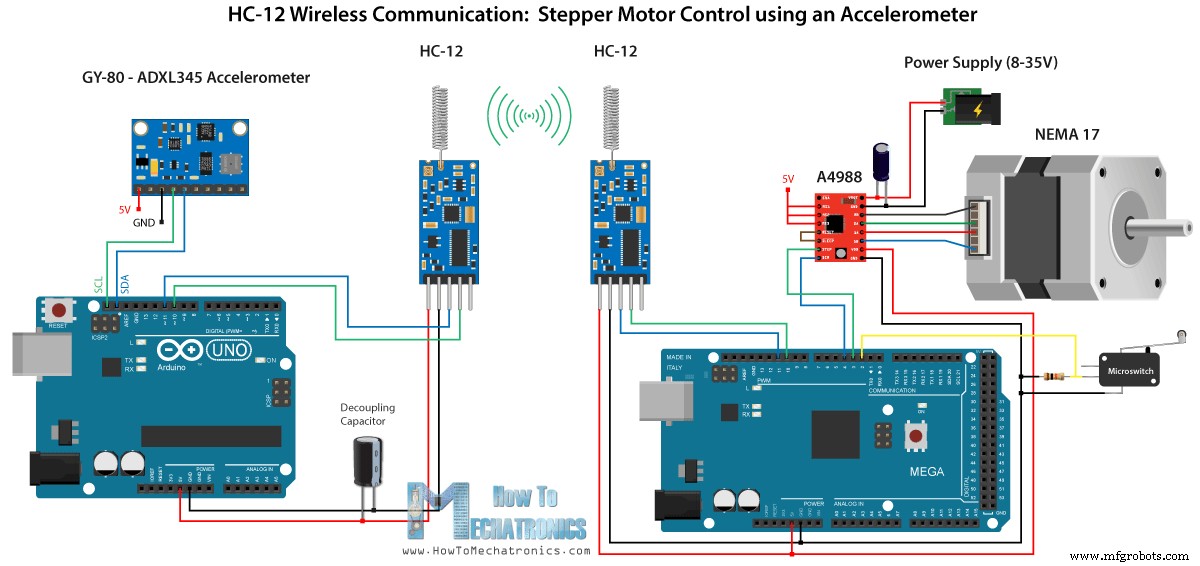
Ahora echemos un vistazo al tercer ejemplo. Aquí controlamos la posición del motor paso a paso en el segundo Arduino, utilizando el módulo de acelerómetro en el primer Arduino.
El circuito también contiene un microinterruptor para encontrar la posición inicial del motor paso a paso a 0 grados.
Puede obtener los componentes necesarios para este ejemplo en los siguientes enlaces:
Tenga en cuenta aquí que ya tengo tutoriales detallados sobre cómo conectar y usar tanto el acelerómetro como el motor paso a paso, por lo que para este ejemplo solo explicaré la parte del código HC-12.
Primer Arduino – Código del transmisor:
Segundo Arduino – Código del receptor:
Descripción de los códigos:
Así que primero definimos los pines e inicializamos los módulos en la sección de configuración. Luego leemos los valores de los ejes X e Y del acelerómetro y los asignamos a valores de 0 a 180 grados. Los valores que provienen del acelerómetro a veces pueden ser inestables o agitados, por lo que para suavizar el resultado utilicé el valor promedio de cien lecturas.
Para suavizar aún más, enviaré el nuevo valor del ángulo solo si difiere del anterior en 2.
Tenga en cuenta aquí que al enviar el ángulo al módulo HC-12, también envío el carácter "s" al frente y el carácter "e" después, lo que me ayudará cuando reciba los datos en el segundo Arduino.
En el segundo Arduino esperamos hasta que llegue el marcador de inicio "s", luego leemos el valor del ángulo hasta que llegue el marcador final "e". De esta manera estamos seguros de que recibiremos solo el valor del ángulo.
Luego, convertimos el valor a entero y mapeamos el valor de 0 a 1600 pasos, lo que corresponde a la resolución de decimosexto paso seleccionada en el controlador paso a paso A4988. Luego giramos el motor paso a paso al ángulo actual.
Así que eso sería todo por este tutorial de Arduino. No dude en hacer cualquier pregunta en la sección de comentarios a continuación.Resumen
Módulo de comunicación inalámbrica HC-12
Arduino y HC-12
Ejemplo 01 – Código Arduino
/*    Arduino Long Range Wireless Communication using HC-12
                      Example 01
   by Dejan Nedelkovski, www.HowToMechatronics.com
*/

#include <SoftwareSerial.h>

SoftwareSerial HC12(10, 11); // HC-12 TX Pin, HC-12 RX Pin

void setup() {
  Serial.begin(9600);             // Serial port to computer
  HC12.begin(9600);               // Serial port to HC12

}

void loop() {
  while (HC12.available()) {        // If HC-12 has data
    Serial.write(HC12.read());      // Send the data to Serial monitor
  }
  while (Serial.available()) {      // If Serial monitor has data
    HC12.write(Serial.read());      // Send that data to HC-12
  }
}Code language: Arduino (arduino)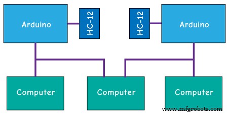
Comandos AT:
Ejemplo 02
/*    Arduino Long Range Wireless Communication using HC-12
    Example 02 - Changing channels using push buttons - Buttons side
   by Dejan Nedelkovski, www.HowToMechatronics.com
*/

#include <SoftwareSerial.h>

#define setPin 6
#define button1 4
#define button2 3

SoftwareSerial HC12(10, 11);         // HC-12 TX Pin, HC-12 RX Pin

byte incomingByte;
String readBuffer = "";

int button1State = 0;
int button1Pressed = 0;
int button2State = 0;
int button2Pressed = 0;

void setup() {
  Serial.begin(9600);                   // Open serial port to computer
  HC12.begin(9600);                     // Open serial port to HC12
  pinMode(setPin, OUTPUT);
  pinMode(button1, INPUT);
  pinMode(button2, INPUT);
  digitalWrite(setPin, HIGH);           // HC-12 normal, transparent mode
}

void loop() {
  // ==== Storing the incoming data into a String variable
  while (HC12.available()) {             // If HC-12 has data
    incomingByte = HC12.read();          // Store each icoming byte from HC-12
    readBuffer += char(incomingByte);    // Add each byte to ReadBuffer string variable
  }
  delay(100);
  // ==== Sending data from one HC-12 to another via the Serial Monitor
  while (Serial.available()) {
    HC12.write(Serial.read());
  }

  // ==== If button 1 is pressed, set the channel 01
  button1State = digitalRead(button1);
  if (button1State == HIGH & button1Pressed == LOW) {
    button1Pressed = HIGH;
    delay(20);
  }
  if (button1Pressed == HIGH) {
    HC12.print("AT+C001");               // Send the AT Command to the other module
    delay(100);
    //Set AT Command Mode
    digitalWrite(setPin, LOW);           // Set HC-12 into AT Command mode
    delay(100);                          // Wait for the HC-12 to enter AT Command mode
    HC12.print("AT+C001");               // Send AT Command to HC-12
    delay(200);
    while (HC12.available()) {           // If HC-12 has data (the AT Command response)
      Serial.write(HC12.read());         // Send the data to Serial monitor
    }
    Serial.println("Channel successfully changed");
    digitalWrite(setPin, HIGH);          // Exit AT Command mode
    button1Pressed = LOW;
  }

  // ====  If button 2 is pressed, set the channel 02
  button2State = digitalRead(button2);
  if (button2State == HIGH & button2Pressed == LOW) {
    button2Pressed = HIGH;
    delay(100);
  }
  if (button2Pressed == HIGH) {
    HC12.print("AT+C002"); // Send the AT Command to the other module
    delay(100);
    //Set AT Command Mode
    digitalWrite(setPin, LOW);           // Set HC-12 into AT Command mode
    delay(100);                          // Wait for the HC-12 to enter AT Command mode
    HC12.print("AT+C002");               // Send AT Command to HC-12
    delay(200);
    while (HC12.available()) {           // If HC-12 has data (the AT Command response)
      Serial.write(HC12.read());         // Send the data to Serial monitor
    }
    Serial.println("Channel successfully changed");
    digitalWrite(setPin, HIGH);
    button2Pressed = LOW;
  }
  checkATCommand();
  readBuffer = "";                       // Clear readBuffer
}
// ==== Custom function - Check whether we have received an AT Command via the Serial Monitor
void checkATCommand () {
  if (readBuffer.startsWith("AT")) {     // Check whether the String starts with "AT"
    digitalWrite(setPin, LOW);           // Set HC-12 into AT Command mode
    delay(200);                          // Wait for the HC-12 to enter AT Command mode
    HC12.print(readBuffer);              // Send AT Command to HC-12
    delay(200);
    while (HC12.available()) {           // If HC-12 has data (the AT Command response)
      Serial.write(HC12.read());         // Send the data to Serial monitor
    }
    digitalWrite(setPin, HIGH);          // Exit AT Command mode
  }
}Code language: Arduino (arduino)/* Arduino Long Range Wireless Communication using HC-12
Example 02 - Changing channels using push buttons
by Dejan Nedelkovski, www.HowToMechatronics.com
*/
#include <SoftwareSerial.h>
#define setPin 6
SoftwareSerial HC12(10, 11); // HC-12 TX Pin, HC-12 RX Pin
byte incomingByte;
String readBuffer = "";
void setup() {
Serial.begin(9600); // Open serial port to computer
HC12.begin(9600); // Open serial port to HC12
pinMode(setPin, OUTPUT);
digitalWrite(setPin, HIGH); // HC-12 normal mode
}
void loop() {
// ==== Storing the incoming data into a String variable
while (HC12.available()) { // If HC-12 has data
incomingByte = HC12.read(); // Store each icoming byte from HC-12
readBuffer += char(incomingByte); // Add each byte to ReadBuffer string variable
}
delay(100);
// ==== Sending data from one HC-12 to another via the Serial Monitor
while (Serial.available()) {
HC12.write(Serial.read());
}
// === If button 1 is pressed, set channel 01
if (readBuffer == "AT+C001") {
digitalWrite(setPin, LOW); // Set HC-12 into AT Command mode
delay(100); // Wait for the HC-12 to enter AT Command mode
HC12.print(readBuffer); // Send AT Command to HC-12 ("AT+C001")
delay(200);
while (HC12.available()) { // If HC-12 has data (the AT Command response)
Serial.write(HC12.read()); // Send the data to Serial monitor
}
Serial.println("Channel successfully changed");
digitalWrite(setPin, HIGH); // Exit AT Command mode
readBuffer = "";
}
// === If button 2 is pressed, set channel 02
if (readBuffer == "AT+C002") {
digitalWrite(setPin, LOW); // Set HC-12 into AT Command mode
delay(100); // Wait for the HC-12 to enter AT Command mode
HC12.print(readBuffer); // Send AT Command to HC-12
delay(200);
while (HC12.available()) { // If HC-12 has data (the AT Command response)
Serial.write(HC12.read()); // Send the data to Serial monitor
}
Serial.println("Channel successfully changed");
digitalWrite(setPin, HIGH); // Exit AT Command mode
readBuffer = "";
}
checkATCommand();
readBuffer = ""; // Clear readBuffer
}
// ==== Custom function - Check whether we have received an AT Command via the Serial Monitor
void checkATCommand () {
if (readBuffer.startsWith("AT")) { // Check whether the String starts with "AT"
digitalWrite(setPin, LOW); // Set HC-12 into AT Command mode
delay(100); // Wait for the HC-12 to enter AT Command mode
HC12.print(readBuffer); // Send AT Command to HC-12
delay(200);
while (HC12.available()) { // If HC-12 has data (the AT Command response)
Serial.write(HC12.read()); // Send the data to Serial monitor
}
digitalWrite(setPin, HIGH); // Exit AT Command mode
}
}Code language: Arduino (arduino)// ==== Storing the incoming data into a String variable
while (HC12.available()) { // If HC-12 has data
incomingByte = HC12.read(); // Store each icoming byte from HC-12
readBuffer += char(incomingByte); // Add each byte to ReadBuffer string variable
}Code language: Arduino (arduino)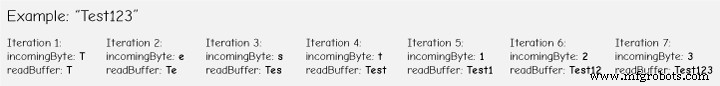
if (button1Pressed == HIGH) {
    HC12.print("AT+C001");               // Send the AT Command to the other module
    delay(100);
    //Set AT Command Mode
    digitalWrite(setPin, LOW);           // Set HC-12 into AT Command mode
    delay(100);                          // Wait for the HC-12 to enter AT Command mode
    HC12.print("AT+C001");               // Send AT Command to HC-12
    delay(200);
    while (HC12.available()) {           // If HC-12 has data (the AT Command response)
      Serial.write(HC12.read());         // Send the data to Serial monitor
    }
    Serial.println("Channel successfully changed");
    digitalWrite(setPin, HIGH);          // Exit AT Command mode
    button1Pressed = LOW;
}Code language: Arduino (arduino)// At the second Arduino
// === If button 1 is pressed, set channel 01
if (readBuffer == "AT+C001") {
digitalWrite(setPin, LOW); // Set HC-12 into AT Command mode
delay(100); // Wait for the HC-12 to enter AT Command mode
HC12.print(readBuffer); // Send AT Command to HC-12 ("AT+C001")
delay(200);
while (HC12.available()) { // If HC-12 has data (the AT Command response)
Serial.write(HC12.read()); // Send the data to Serial monitor
}
Serial.println("Channel successfully changed");
digitalWrite(setPin, HIGH); // Exit AT Command mode
readBuffer = "";
}Code language: Arduino (arduino)while (HC12.available()) { // If HC-12 has data (the AT Command response)
Serial.write(HC12.read()); // Send the data to Serial monitor
}Code language: Arduino (arduino)// ==== Custom function - Check whether we have received an AT Command via the Serial Monitor
void checkATCommand () {
if (readBuffer.startsWith("AT")) { // Check whether the String starts with "AT"
digitalWrite(setPin, LOW); // Set HC-12 into AT Command mode
delay(200); // Wait for the HC-12 to enter AT Command mode
HC12.print(readBuffer); // Send AT Command to HC-12
delay(200);
while (HC12.available()) { // If HC-12 has data (the AT Command response)
Serial.write(HC12.read()); // Send the data to Serial monitor
}
digitalWrite(setPin, HIGH); // Exit AT Command mode
}
}Code language: Arduino (arduino)HC-12 Comunicación inalámbrica:Control de motor paso a paso usando un acelerómetro
/*   Arduino Long Range Wireless Communication using HC-12
     Example 03 - Stepper Motor Control using Accelerometer - Transmitter, Accelerometer
    by Dejan Nedelkovski, www.HowToMechatronics.com
*/

#include <SoftwareSerial.h>
#include <Wire.h>

SoftwareSerial HC12(10, 11); // HC-12 TX Pin, HC-12 RX Pin

float angle;
int lastAngle = 0;
int count = 0;
int angleSum = 0;

//--- Accelerometer Register Addresses
#define Power_Register 0x2D
#define X_Axis_Register_DATAX0 0x32 // Hexadecima address for the DATAX0 internal register.
#define X_Axis_Register_DATAX1 0x33 // Hexadecima address for the DATAX1 internal register.
#define Y_Axis_Register_DATAY0 0x34
#define Y_Axis_Register_DATAY1 0x35
#define Z_Axis_Register_DATAZ0 0x36
#define Z_Axis_Register_DATAZ1 0x37
int ADXAddress = 0x53;  //Device address in which is also included the 8th bit for selecting the mode, read in this case.
int X0, X1, X_out;
int Y0, Y1, Y_out;
int Z1, Z0, Z_out;
float Xa, Ya, Za;

void setup() {
  HC12.begin(9600);               // Open serial port to HC12
  Wire.begin(); // Initiate the Wire library
  Serial.begin(9600);
  delay(100);

  Wire.beginTransmission(ADXAddress);
  Wire.write(Power_Register); // Power_CTL Register
  // Enable measurement
  Wire.write(8); // Bit D3 High for measuring enable (0000 1000)
  Wire.endTransmission();
}
void loop() {
  // X-axis
  Wire.beginTransmission(ADXAddress); // Begin transmission to the Sensor
  //Ask the particular registers for data
  Wire.write(X_Axis_Register_DATAX0);
  Wire.write(X_Axis_Register_DATAX1);
  Wire.endTransmission(); // Ends the transmission and transmits the data from the two registers
  Wire.requestFrom(ADXAddress, 2); // Request the transmitted two bytes from the two registers
  if (Wire.available() <= 2) { //
    X0 = Wire.read(); // Reads the data from the register
    X1 = Wire.read();
    /* Converting the raw data of the X-Axis into X-Axis Acceleration
      - The output data is Two's complement
      - X0 as the least significant byte
      - X1 as the most significant byte */
    X1 = X1 << 8;
    X_out = X0 + X1;
    Xa = X_out / 256.0; // Xa = output value from -1 to +1, Gravity acceleration acting on the X-Axis
  }
  //Serial.print("Xa= ");
  //Serial.println(X_out);

  // Y-Axis
  Wire.beginTransmission(ADXAddress);
  Wire.write(Y_Axis_Register_DATAY0);
  Wire.write(Y_Axis_Register_DATAY1);
  Wire.endTransmission();
  Wire.requestFrom(ADXAddress, 2);
  if (Wire.available() <= 2) {
    Y0 = Wire.read();
    Y1 = Wire.read();
    Y1 = Y1 << 8;
    Y_out = Y0 + Y1;
    Ya = Y_out / 256.0;
  }

  // Combine X and Y values for getting the angle value from 0 to 180 degrees
  if (Y_out > 0) {
    angle = map(Y_out, 0, 256, 90, 0);
  }
  else if (Y_out < 0) {
    angle = map(Y_out, 256, 0, 90, 0);
    angle = 90 - angle;
  }
  if (X_out < 0 & Y_out < 0) {
    angle = 180;
  }
  if (X_out < 0 & Y_out >0) {
    angle = 0;
  }

  // float to int
  int angleInt = int(angle);
  // Makes 100 accelerometer readings and sends the average for smoother result
  angleSum = angleSum + angleInt;
  count++;
  if (count >= 100) {
    angleInt = angleSum / 100;
    angleSum = 0;
    count = 0;
    // Some more smoothing of acceleromter reading - sends the new angle only if it differes from the previous one by +-2
    if (angleInt > lastAngle + 2 || angleInt < lastAngle - 2) {
      Serial.println(angleInt);
      String angleString = String(angleInt);
      //sends the angle value with start marker "s" and end marker "e"
      HC12.print("s" + angleString + "e");
      delay(10);
      lastAngle = angleInt;
      angleSum = 0;
      count = 0;
    }
  }
}
Code language: Arduino (arduino)/* Arduino Long Range Wireless Communication using HC-12
Example 03 - Stepper Motor Control using Accelerometer - Receiver, Stepper Motor
by Dejan Nedelkovski, www.HowToMechatronics.com
*/
#include <SoftwareSerial.h>
SoftwareSerial HC12(10, 11); // HC-12 TX Pin, HC-12 RX Pin
char incomingByte;
String readBuffer = "";
// defines pins numbers
const int dirPin = 4;
const int stepPin = 3;
const int button = 2;
int currentAngle = 0;
int lastAngle = 0;
int rotate = 0;
void setup() {
Serial.begin(9600); // Open serial port to computer
HC12.begin(9600); // Open serial port to HC12
// Sets the two pins as Outputs
pinMode(dirPin, OUTPUT);
pinMode(stepPin, OUTPUT);
// Microswitch input, with internal pull-up resistor activated
pinMode(button, INPUT_PULLUP);
delay(10);
digitalWrite(dirPin, HIGH);
boolean startingPosition = true;
while (startingPosition) {
digitalWrite(stepPin, HIGH);
delayMicroseconds(200);
digitalWrite(stepPin, LOW);
delayMicroseconds(200);
if (digitalRead(button) == LOW) {
startingPosition = false;
}
}
delay(100);
}
void loop() {
readBuffer = "";
boolean start = false;
// Reads the incoming angle
while (HC12.available()) { // If HC-12 has data
incomingByte = HC12.read(); // Store each icoming byte from HC-12
delay(5);
// Reads the data between the start "s" and end marker "e"
if (start == true) {
if (incomingByte != 'e') {
readBuffer += char(incomingByte); // Add each byte to ReadBuffer string variable
}
else {
start = false;
}
}
// Checks whether the received message statrs with the start marker "s"
else if ( incomingByte == 's') {
start = true; // If true start reading the message
}
}
// Converts the string into integer
currentAngle = readBuffer.toInt();
// Makes sure it uses angles between 0 and 180
if (currentAngle > 0 && currentAngle < 180) {
// Convert angle value to steps (depending on the selected step resolution)
// A cycle = 200 steps, 180deg = 100 steps ; Resolution: Sixteenth step x16
currentAngle = map(currentAngle, 0, 180, 0, 1600);
//Serial.println(currentAngle); // Prints the angle on the serial monitor
digitalWrite(dirPin, LOW); // Enables the motor to move in a particular direction
// Rotates the motor the amount of steps that differs from the previous positon
if (currentAngle != lastAngle) {
if (currentAngle > lastAngle) {
rotate = currentAngle - lastAngle;
for (int x = 0; x < rotate; x++) {
digitalWrite(stepPin, HIGH);
delayMicroseconds(400);
digitalWrite(stepPin, LOW);
delayMicroseconds(400);
}
}
// rotate the other way
if (currentAngle < lastAngle) {
rotate = lastAngle - currentAngle;
digitalWrite(dirPin, HIGH); //Changes the rotations direction
for (int x = 0; x < rotate; x++) {
digitalWrite(stepPin, HIGH);
delayMicroseconds(400);
digitalWrite(stepPin, LOW);
delayMicroseconds(400);
}
}
}
lastAngle = currentAngle; // Remembers the current/ last positon
}
}Code language: Arduino (arduino)// Makes 100 accelerometer readings and sends the average for smoother result
angleSum = angleSum + angleInt;
count++;
if (count >= 100) {
angleInt = angleSum / 100;
angleSum = 0;
count = 0;
// Some more smoothing of acceleromter reading - sends the new angle only if it differes from the previous one by +-2
if (angleInt > lastAngle + 2 || angleInt < lastAngle - 2) {
Serial.println(angleInt);
String angleString = String(angleInt);
//sends the angle value with start marker "s" and end marker "e"
HC12.print("s" + angleString + "e");
delay(10);
lastAngle = angleInt;
angleSum = 0;
count = 0;
}
}Code language: Arduino (arduino)// Reads the incoming angle
while (HC12.available()) { // If HC-12 has data
incomingByte = HC12.read(); // Store each icoming byte from HC-12
delay(5);
// Reads the data between the start "s" and end marker "e"
if (start == true) {
if (incomingByte != 'e') {
readBuffer += char(incomingByte); // Add each byte to ReadBuffer string variable
}
else {
start = false;
}
}
// Checks whether the received message statrs with the start marker "s"
else if ( incomingByte == 's') {
start = true; // If true start reading the message
}
}Code language: Arduino (arduino)
Proceso de manufactura
- Alcance de comunicación inalámbrica
- Por qué la conexión inalámbrica de largo alcance alimentada por batería es perjudicial
- Animación LCD y juegos
- Generador de ondas JX
- Módulo GPS u-blox LEA-6H 02 con Arduino y Python
- Escáner de temperatura por infrarrojos inalámbrico
- Python3 y comunicación Arduino
- Radio FM usando Arduino y RDA8057M
- Un sistema de detección de caídas basado en Arduino, Windows y Azure
- Reloj de alarma ArduRadio
- Telémetro ultrasónico