El IC complementario
Componentes y suministros
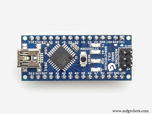 |
| × | 1 | |||
 |
| × | 1 | |||
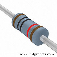 |
| × | 4 | |||
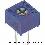 |
| × | 1 | |||
 |
| × | 2 | |||
 |
| × | 3 | |||
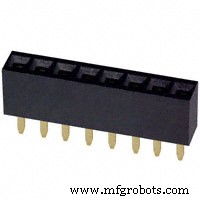 |
| × | 4 | |||
 |
| × | 2 | |||
 |
| × | 1 | |||
 |
| × | 1 |
Herramientas y máquinas necesarias
 |
| |||
 |
|
Acerca de este proyecto
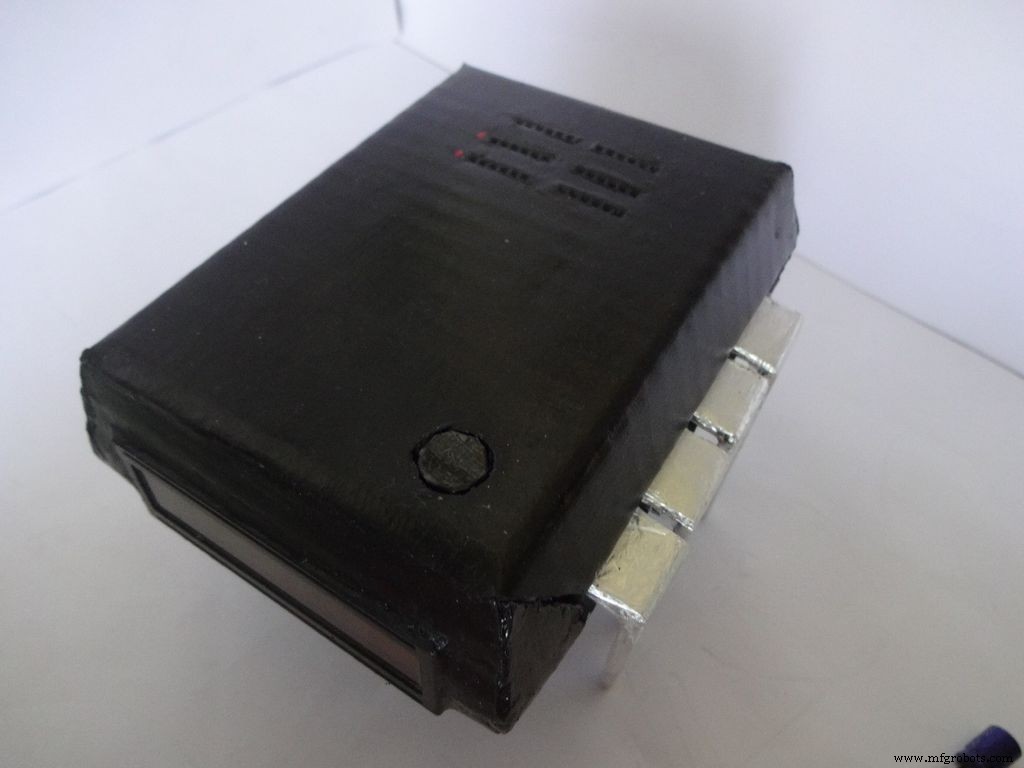

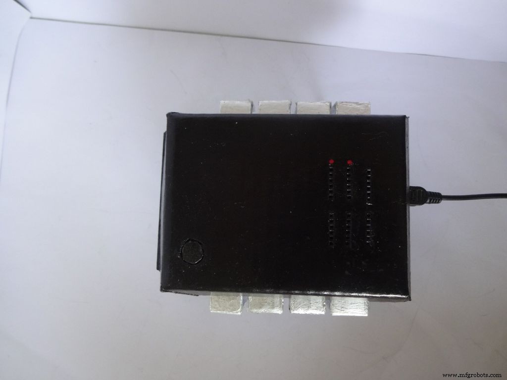
El Companion IC es un reloj + ohmímetro + medidor de capacitancia + probador de diodos muy atractivo. ¡Enciéndalo presionando el Pin 1 del IC! Guárdelo en su banco de trabajo para una prueba rápida de los componentes y el tiempo de verificación. Puede funcionar con baterías o con USB si tiene un suministro cerca de su mesa de trabajo.
¡Siempre quise publicar un proyecto pero nunca encontré nada único para hacer hasta ahora! La idea se me ocurrió cuando quise probar algunos condensadores para ver si estaban defectuosos o no. Solo tenía un multímetro disponible y no tenía una función de medición de capacitancia. Después de buscarlo, supe que Arduino puede hacer esto. Decidí que haría uno, pero ver los pines sin usar en el Arduino no fue muy satisfactorio, ¡así que decidí agregar un ohmímetro de rango automático, un probador rápido de LED / diodos y un reloj RTC también! También quería que mida directamente los valores conectando el componente y no usando ninguna sonda. El diseño tenía que ser único, así que después de una lluvia de ideas, ¡se hizo el diseño del IC!
Editar (01/07/2016):se ha agregado la prueba de continuidad opcional; consulte la sección de comentarios.
Este artículo explica con gran detalle cómo hice esto y cómo tú también puedes hacerlo por tu cuenta. ¡Es amigable para principiantes y cualquiera con 2-3 semanas de experiencia en Arduino / Electrónica puede construirlo!
El diseño es modificable y puede eliminar / agregar nuevas funciones según sus requisitos. Hice el estuche con cartón, pero si tienes las habilidades, puedes hacerlo con madera o imprimirlo en 3D.
He intentado tomar y adjuntar fotografías en cada paso que hice (¡muchas en cada paso!). La mayoría de estos se tomaron varias veces hasta que obtuve el mejor ángulo / luz, pero aún algunos de ellos están un poco borrosos, ya que sostenerlo todo con las dos manos a veces es difícil.
Rompí todo el código y el cableado en piezas y pasos, tal como lo hice. El código incluido está muy comentado y debidamente sangrado. A medida que avanzamos. Combinaremos todo el código y el cableado paso a paso para crear el IC final. Esto debería ayudar a cualquiera a entenderlo claramente. Si no es así, avíseme en los comentarios.
Incluso si decides no hacer uno, pruébalo en una placa de pruebas o al menos lee esto una vez, ya que debe haber algún método, truco o algo que puedas aprender aquí y te será útil algún día (en serio, nunca se sabe cuándo). hace clic!)
Paso 1:Herramientas y componentes necesarios
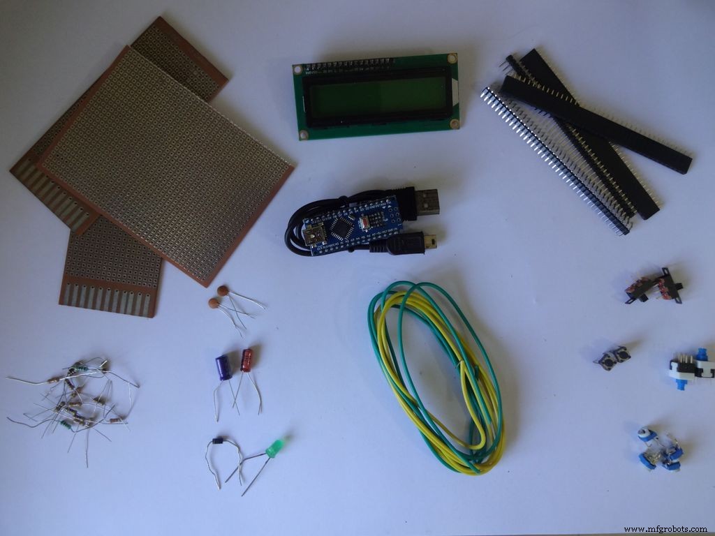

Lista de componentes y materiales utilizados (enlaces de la tienda solo como referencia):
- 1x Arduino Nano V3, Usé un clon con CH340G - ebay
- Cable mini USB para Arduino Nano - Mini no Micro !
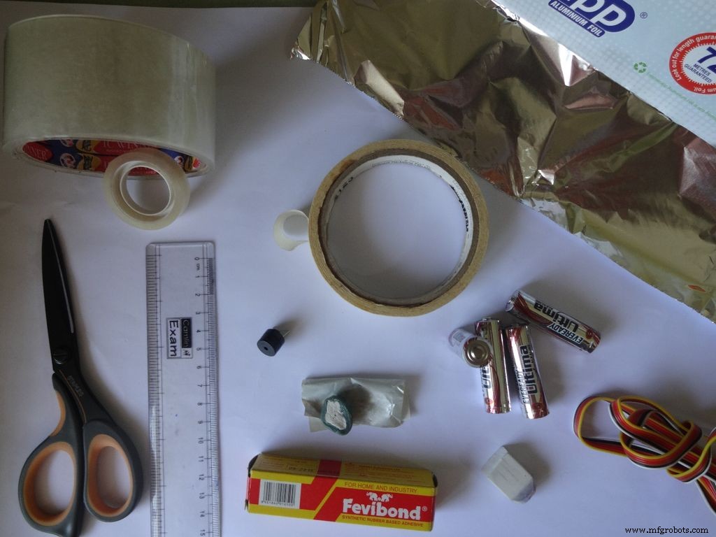
- Cartón - Usé una caja de embalaje, de ~ 2 mm de grosor. Pregúntele a su vecino, amigos, vaya a buscar basura si no puede encontrar uno.
- 4x Resistencia de 10 k ohmios - fácilmente disponible
- 2x Resistencia de 220 ohmios - fácilmente disponible
- 1x (1k, 4.7k, 47k, 100k) resistencias de ohmios - fácilmente disponible
- 1 potenciómetro pequeño de 10 k ohmios para el control de contraste de la pantalla LCD ... cualquier tamaño pequeño funcionará .-- ebay
- 2x Micro pulsadores para el botón de reinicio y cambio de modo, los comunes que usa en una placa de pruebas.
- 3 interruptores deslizantes pequeños , para habilitar la retroiluminación, pines 0 y 1, estos pines deben desactivarse mientras se usa Serial - ebay
- 1x Interruptor pulsador mantenido / de palanca / con enclavamiento, para interruptor de encendido - ebay
- Algunos capacitores, diodos, leds solo para pruebas, los usará algún día de todos modos.
- 4x Tira de clavijas de encabezado hembra - ebay (40 pines por tira)
- 2x Tira de clavijas de encabezado macho - ebay (40 pines por tira)
- 1x LCD de 16 x 2 caracteres - ebay
- 1x Módulo RTC DS3231 o DS1307 (RTC significa reloj en tiempo real) - No compre los baratos en ebay. Estos usan chips falsos y son inexactos. Compre esto, esto o esto. Cualquiera de estos funcionará.
- 4 x pilas AA (o AAA. Usar AAA será mucho más fácil, pero la capacidad de la batería es menor)
- 1x soporte de 4 pilas AA (o AAA) , variante plana - ebay
- Cable de una sola hebra , los que se usan para las protoboards, calibre 22
- Cable plano (o se pueden usar algunos cables de par trenzado delgados) - ebay
- 2x Tuerca y perno pequeños - Usé los de mi antiguo juego de Meccano (los pernos miden 1,3 cm de largo)
- Pinceles y pintura acrílica negra
Herramientas necesarias:
- Soldador
- Soldar
- Mecha / trenza para desoldar (¡para cuando lo estropees!)
- Pistola de pegamento
- Cinta adhesiva
- Cinta de violonchelo, transparente
- Pelacables, pinza
- Cortador de cajas afilado
- Tijeras afiladas
Paso 2:Ohmímetro - Concepto

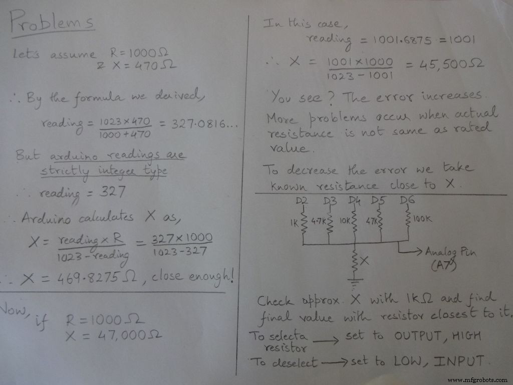
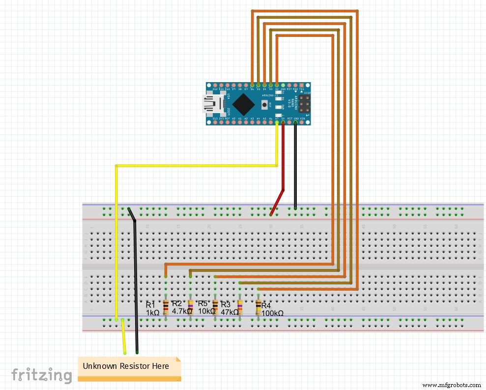
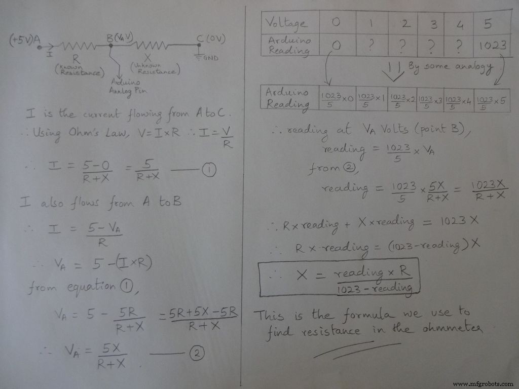
La idea básica de medir la resistencia proviene del divisor de voltaje.
Los valores de resistencia son modificables, cambian los valores de r1, r2, etc. También configure los rangos (para rango automático) en consecuencia. Vea el código a continuación, descárguelo de los archivos al final y pruebe el ohmímetro en una placa
Si está configurando Nano por primera vez, el controlador CH340G se puede descargar aquí, funciona con Windows 7, 8, 8.1 y 10. Los usuarios de Mac verifiquen aquí.
Seleccione "Arduino Nano" en el menú de placas y el puerto COM correcto. ¡Subir!
Código
// Pin analógico utilizado para encontrar la resistenciaint Apin =7; // valores de r1 a r5float r1 =1000; float r2 =4700; float r3 =10000; float r4 =47000; float r5 =100000; / / pines de r1 a r5int r1_pin =2; int r2_pin =3; int r3_pin =4; int r4_pin =5; int r5_pin =6; lectura flotante =0; // leer desde el pin analógico y almacenar herefloat R =0; // calcula desconocido y almacena hereString finalR; // valor final que se mostrará junto con unitint caseno; // para depurar, almacena el número de caso // dividimos el rango completo en casos y asignamos a cada uno un número, total 5 casos // caso1:menos de 2850 // caso2:2850 a 7350 // caso3:7350 a 28500 // case4:28500 a 73500 // case5:más de 73500 # include // necesario para convertir float en string, tiene la función String (float, n). Explicado a continuación.void setup () {Serial.begin (9600);} void loop () {// primero encontramos una resistencia desconocida usando una resistencia de 1kOhm // Por lo tanto, deshabilite R2, R3, R4 y R5 digitalWrite (r2_pin, LOW); // cambia cada pin a LOW antes de configurarlo como INPUT pinMode (r2_pin, INPUT); // girarlo INPUT cuando está en HIGH habilita la resistencia pullup interna digitalWrite (r3_pin, LOW); pinMode (r3_pin, ENTRADA); digitalWrite (r4_pin, BAJO); pinMode (r4_pin, ENTRADA); digitalWrite (r5_pin, BAJO); pinMode (r5_pin, ENTRADA); pinMode (r1_pin, SALIDA); digitalWrite (r1_pin, ALTO); // leer y calcular la lectura de resistencia =analogRead (Apin); R =(lectura * r1) / (1023-lectura); // si valor <2850, finalR =valor (usando 1kOhm) if (R <2850) {caseno =1; if (R <1000) {// si el valor es menor que 1000 use "Ohm" no "kOhm" finalR =String (R, 2) + "Ohm"; // String (float, n) Convirtiendo float en string con n dígitos después del decimal // adjunte "Ohm" después del valor a la cadena, '+' une dos cadenas aquí} else {// use "kOhm R =R / 1000; finalR =String (R, 2) + "kOhm";}} // si el valor está entre 2850 y 7350, use el valor obtenido por 4.7kOhm else if (R> =2850 &&R <7350) {caseno =2; digitalWrite (r1_pin , LOW); // Habilitar solo 4.7kOhm pinMode (r1_pin, INPUT); digitalWrite (r3_pin, LOW); pinMode (r3_pin, INPUT); digitalWrite (r4_pin, LOW); pinMode (r4_pin, INPUT); digitalWrite (r5_pin, LOW) ); pinMode (r5_pin, INPUT); pinMode (r2_pin, OUTPUT); digitalWrite (r2_pin, HIGH); lectura =analogRead (Apin); R =(lectura * r2) / (1023-lectura) / 1000; finalR =String ( R, 2) + "kOhm";} // si el valor está entre 7350 y 28500, use el valor obtenido por 10kOhm else if (R> =7350 &&R <28500) {caseno =3; digitalWrite (r1_pin, LOW); pinMode ( r1_pin, INPUT); digitalWrite (r2_pin, LOW); pinMode (r2_pin, INPUT); digitalWrite (r4_pin, LOW); pinMode (r4_pin, INPUT); digitalWrite (r5_pin, LOW); pinMode (r5_pin, INPUT); pinM oda (r3_pin, SALIDA); digitalWrite (r3_pin, ALTO); lectura =analogRead (Apin); R =(lectura * r3) / (1023-lectura) / 1000; finalR =Cadena (R, 2) + "kOhm"; } // si el valor está entre 28500 y 73500, use el valor obtenido por 47kOhm else if (R> =28500 &&R <73500) {caseno =4; digitalWrite (r1_pin, BAJO); pinMode (r1_pin, ENTRADA); digitalWrite (r2_pin, BAJO); pinMode (r2_pin, ENTRADA); digitalWrite (r3_pin, BAJO); pinMode (r3_pin, ENTRADA); digitalWrite (r5_pin, BAJO); pinMode (r5_pin, ENTRADA); pinMode (r4_pin, SALIDA); digitalWrite (r4_pin, ALTO); lectura =analogRead (Apin); R =(lectura * r4) / (1023-lectura) / 1000; finalR =Cadena (R, 2) + "kOhm"; } // si el valor es mayor que 73500, use el valor obtenido por 100kOhm else if (R> =73500) {caseno =5; digitalWrite (r1_pin, BAJO); pinMode (r1_pin, ENTRADA); digitalWrite (r2_pin, BAJO); pinMode (r2_pin, ENTRADA); digitalWrite (r3_pin, BAJO); pinMode (r3_pin, ENTRADA); digitalWrite (r4_pin, BAJO); pinMode (r4_pin, ENTRADA); pinMode (r5_pin, SALIDA); digitalWrite (r5_pin, ALTO); lectura =analogRead (Apin); R =(lectura * r5) / (1023-lectura) / 1000; finalR =Cadena (R, 2) + "kOhm"; } Serial.println (finalR); // imprimiendo la cadena final con unidades Serial.println (""); retraso (1000);}
Paso 3:Medidor de capacitancia - Concepto
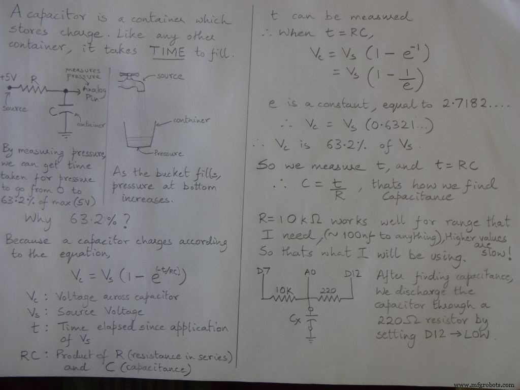

Código
/ * RCTiming_capacitance_meter * concepto de código tomado de Paul Badger 2008 * * El voltaje del capacitor en una constante de tiempo se define como el 63.2% del voltaje de carga. * es decir, un condensador se llena al 63,2% de su capacidad total en 1 constante de tiempo * / int analogPin =0; // pin analógico para medir la tensión del condensador int chargePin =7; // pin para cargar el condensador - conectado a un extremo de la resistencia de carga int downloadPin =12; // pin para descargar el condensador, mismo que se utiliza para la prueba de diodos (chechPin1) float resistorValue =10000.0; // Usamos 10kOhm resistor unsigned long startTime; unsigned long elapsedTime; flotar microFarads; // variable de punto flotante para preservar la precisión, hacer que los cálculos floten nanoFarads; void setup () {pinMode (chargePin, OUTPUT); // establece chargePin para generar digitalWrite (chargePin, LOW); Serial.begin (9600); // inicializar la transmisión en serie para la depuración} void loop () {digitalWrite (chargePin, HIGH); // establece chargePin HIGH y startTime de carga del condensador =millis (); while (analogRead (analogPin) <648) {// 647 es el 63,2% de 1023, que corresponde al voltaje de escala completa} elapsedTime =millis () - startTime; // convierte milisegundos en segundos (10 ^ -3) y Faradios en microFarads (10 ^ 6), neto 10 ^ 3 (1000) microFaradios =((float) elapsedTime / resistorValue) * 1000; // (flotante) convierte el tiempo transcurrido "largo sin firmar" en flotante Serial.print (elapsedTime); // imprime el valor en el puerto serie Serial.print ("mS"); // imprimir unidades if (microFarads> 1) {Serial.print ((largo) microFarads); // imprime el valor en el puerto serie Serial.println ("microFarads"); // imprime unidades} else {// si el valor es menor que un microFaradio, conviértelo a nanoFaradios (10 ^ -9 Faradios). nanoFarads =microFarads * 1000.0; // multiplicar por 1000 para convertir a nanoFarads (10 ^ -9 Farads) Serial.print ((largo) nanoFarads); // imprime el valor en el puerto serie Serial.println ("nanoFarads"); // imprimir unidades} / * descargar el condensador * / digitalWrite (chargePin, LOW); // establece el pin de carga en LOW pinMode (downloadPin, OUTPUT); // establece el pin de descarga en la salida digitalWrite (downloadPin, LOW); // establece el pin de descarga en BAJO while (analogRead (analogPin)> 0) {// espera hasta que el condensador esté completamente descargado} pinMode (downloadPin, INPUT); // establece el pin de descarga de nuevo en input}
Paso 4:prueba de diodos
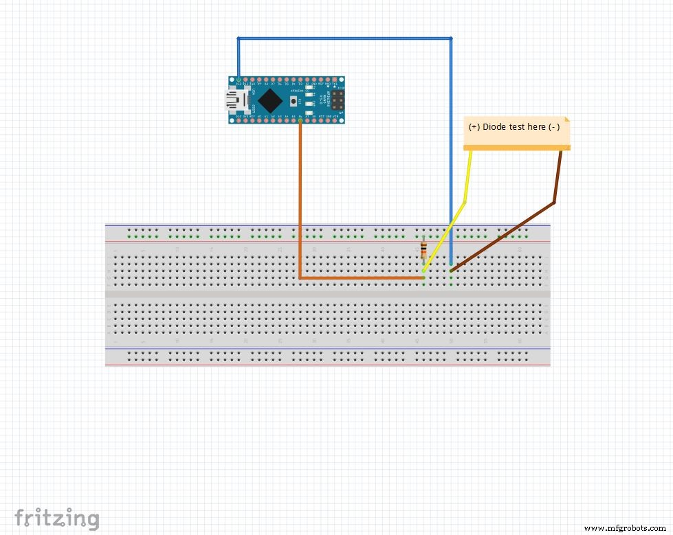
El pin analógico se eleva a 5V con la resistencia de 10k Ohm. Entonces, el pin analógico dice 1023 cuando no hay nada conectado. D12 está configurado en SALIDA , BAJO .
Cuando un diodo tiene polarización directa entre pin analógico ( 5V ) y D12 ( GND ), pin analógico lee 100-400 .
Cuando tiene polarización inversa, fluye prácticamente una corriente muy pequeña y un pin analógico lee 900-1023 .
De esta manera, simplemente podemos encontrar el lado pyn de cualquier diodo. Esto se puede utilizar para comprobar rápidamente los LED y los diodos.
Código
String state ="null"; int checkPin1 =12; int checkPin2 =6; void setup () {Serial.begin (9600);} void loop () {pinMode (checkPin1, OUTPUT); digitalWrite (checkPin1, LOW); // el pin 11 está configurado en bajo // la lectura analógica normalmente es levantada por la resistencia de 10k, por lo que la lectura nula es 1023 // En polarización directa, el pin analógico se conecta a checkPin1, que es LOW. Entonces, leyendo menos de 1023 // Prácticamente una pequeña corriente fluye también en polarización inversa, por lo que tomamos 700 para diferenciar if (analogRead (checkPin2) <700) {state ="forward"; } Serial.println (estado); Serial.println (analogRead (checkPin2)); estado ="nulo"; retraso (500);}
Paso 5:el reloj en tiempo real (RTC)
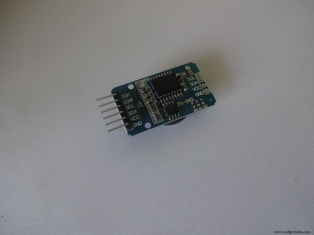
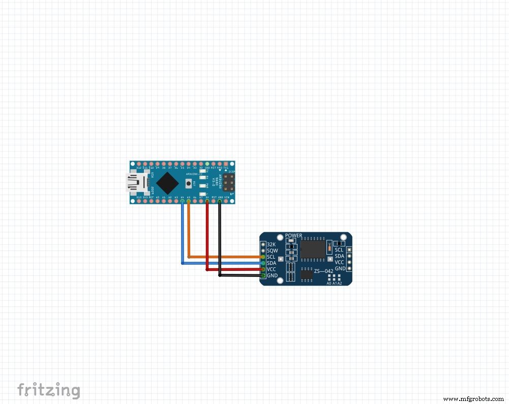
El RTC mantiene información de segundos, minutos, horas, día, fecha, mes y año. Continúa contando incluso cuando se corta la alimentación externa gracias a la pequeña celda de botón que contiene. La fecha al final del mes se ajusta automáticamente para los meses con menos de 31 días, incluidas las correcciones por año bisiesto.
Independientemente del módulo que tenga, usaremos 4 pines: Vcc , GND , SDA y SCL . La SDA y SCL los pines del arduino nano y uno son A4 y A5 respectivamente. ¡Para otros arduinos, búscalo en Google!
Usaremos la biblioteca "RTClib", que hace que configurar y acceder a la hora sea muy fácil. La biblioteca se puede descargar aquí (haga clic en "Descargar ZIP" y extraiga el "RTClib-master" en la carpeta de bibliotecas de Arduino. Más información sobre la instalación de bibliotecas)
Para establecer la hora, descargue el "RTC_set_time.ino" adjunto a este paso y descomente las líneas,
rtc.adjust (DateTime (F (__ DATE__), F (__ TIME__)));
Si desea utilizar el tiempo establecido en su computadora durante la compilación. O
Para establecer una hora personalizada.
Conéctese como se muestra y cargue. Abra Serie monitor a 9600 baudios para ver la hora actual. Verifique nuevamente después de algunas horas para ver cómo se está poniendo al día el RTC.
Asegúrate de recomendar estas líneas y volver a subirlas después de configurar la hora una vez. ¡De lo contrario, lo seguirás reiniciando cada vez que se reinicie Arduino!
Código
// Las funciones de fecha y hora usando un RTC DS1307 conectado a través de I2C y Wire lib # incluyen #include RTC_DS1307 rtc; // creando el objeto "rtc" de RTC_DS1307, objetos se utilizan para acceder a funciones // más sobre objetos y clases:https://www.youtube.com/watch?v=ABRP_5RYhqUchar daysOfTheWeek [7] [12] ={"Sunday", "Monday", "Tuesday", " Miércoles "," Jueves "," Viernes "," Sábado "}; void setup () {Serial.begin (9600); rtc.begin (); // la siguiente línea establece el RTC en la fecha y hora en que se compiló este boceto // rtc.adjust (DateTime (F (__ DATE__), F (__ TIME__))); // Esta línea establece el RTC con una fecha y hora explícitas, por ejemplo para establecer // 21 de enero de 2014 a las 3 a. M., Llamaría:// rtc.adjust (DateTime (2014, 1, 21, 3, 0, 0) );} void loop () {DateTime now =rtc.now (); Serial.print (ahora.año ()); Serial.print ('/'); Serial.print (ahora.mes ()); Serial.print ('/'); Serial.print (ahora.día ()); Serial.print ("("); Serial.print (daysOfTheWeek [ahora.dayOfTheWeek ()]); Serial.print (")"); Serial.print (ahora.hora ()); Serial.print (':'); Serial.print (ahora.minuto ()); Serial.print (':'); Serial.print (ahora.segundo ()); Serial.println (); Serial.println (); retraso (1000);}
Paso 6:Configuración final
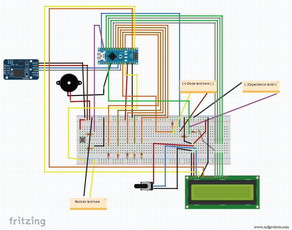
Así que ese es el circuito final después de combinar todos los elementos. El código principal y el archivo de fritzing se adjuntan al final.
Descarga fritzing de fritzing.org si aún no lo has hecho.
Extraiga el archivo Main_code.rar y abra Main_file_rtc.ino. He incluido todas las declaraciones de variables en una definations.h separada archivo de encabezado, se agregará automáticamente cuando abra el código principal.
Las diferentes partes se convierten en funciones: Clock () , findResistance () , findCapcitance () y diodeTest () . Estos están escritos en pestañas separadas, lo que facilita la lectura y los cambios son fáciles de implementar. El archivo principal simplemente verifica el estado del "botón de modo" y llama a las funciones apropiadas.
Otros detalles se explican correctamente en el código mismo.
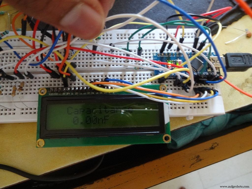
Después de una ejecución de prueba en una placa de pruebas, ¡estamos listos para comenzar a hacer el IC!
Nota:el zumbador, si aún no se utiliza, se puede utilizar cuando sea necesario, por ejemplo, una función de continuidad.
Paso 7:preparación de los conmutadores
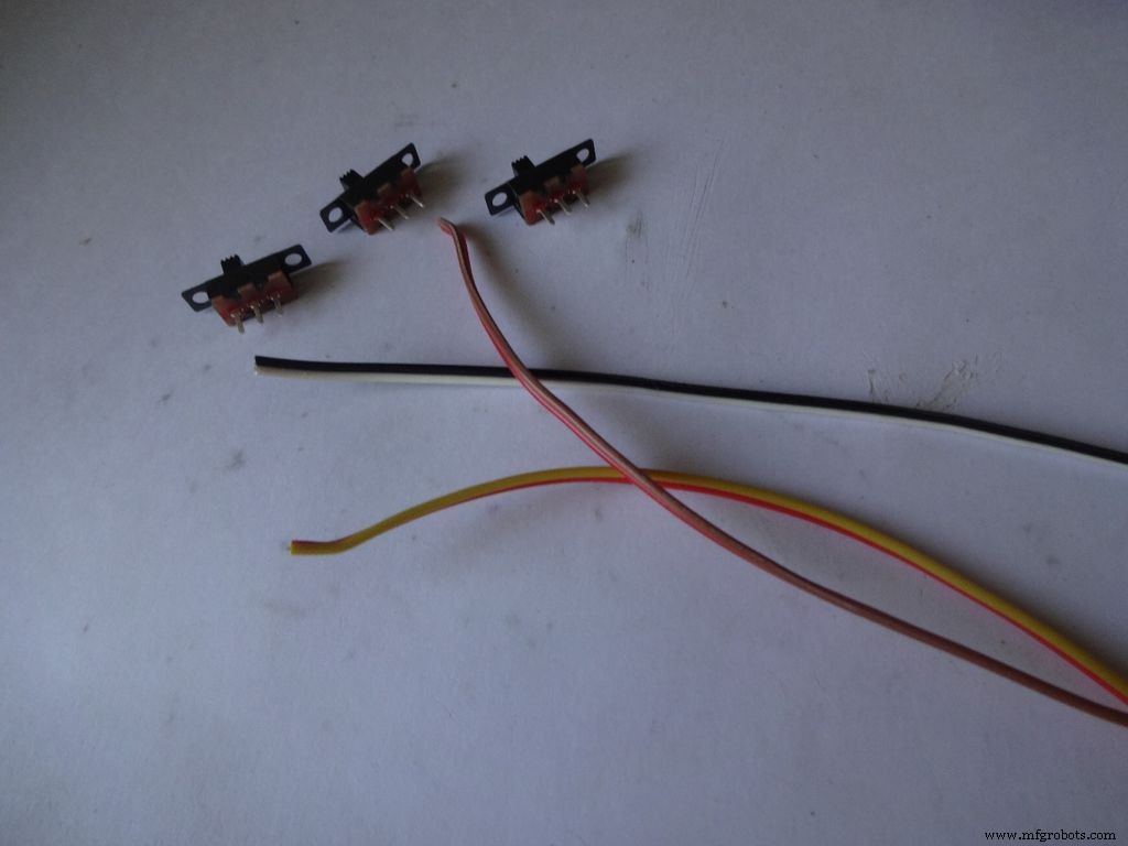
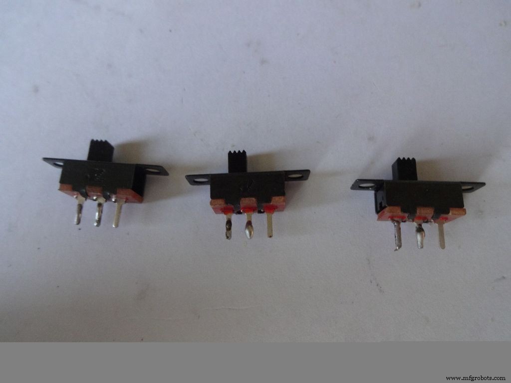
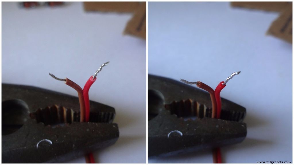

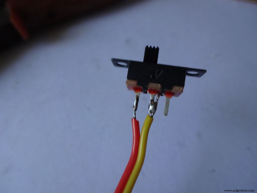
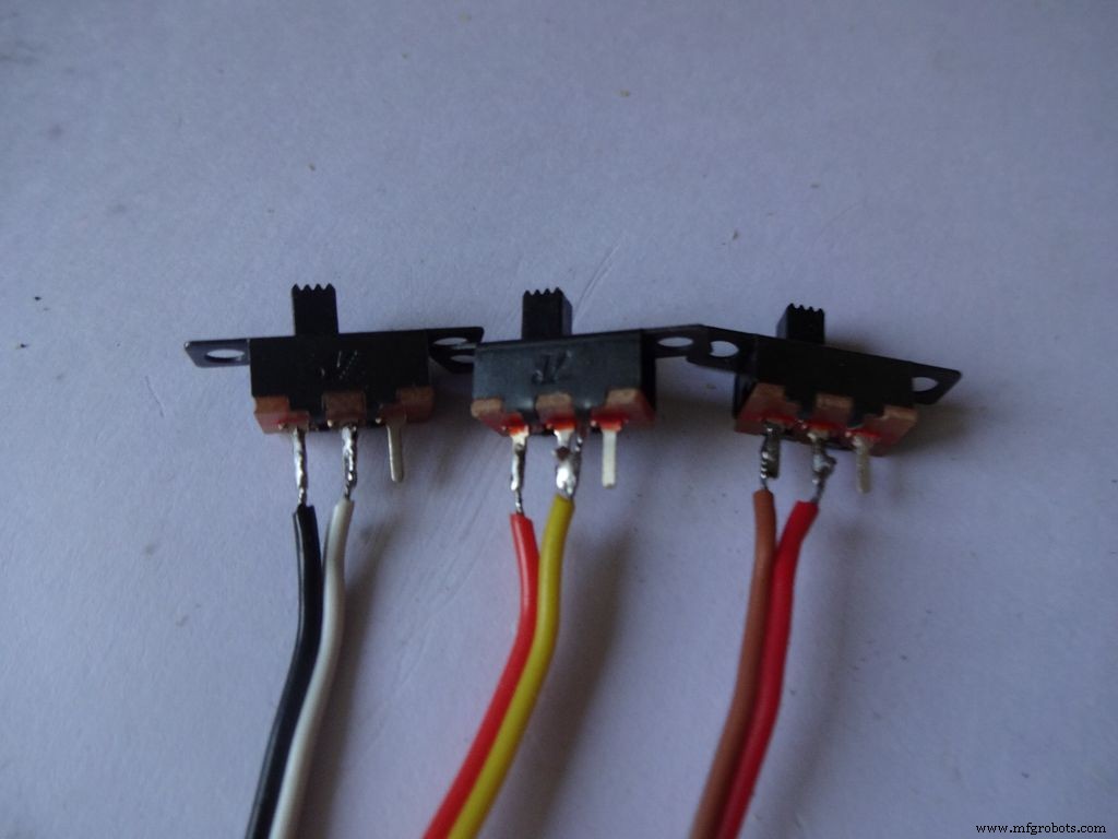

Tome los 3 interruptores deslizantes junto con 3 pares de cables, de unos 10 cm de largo. Divido el cable de cinta para esto.
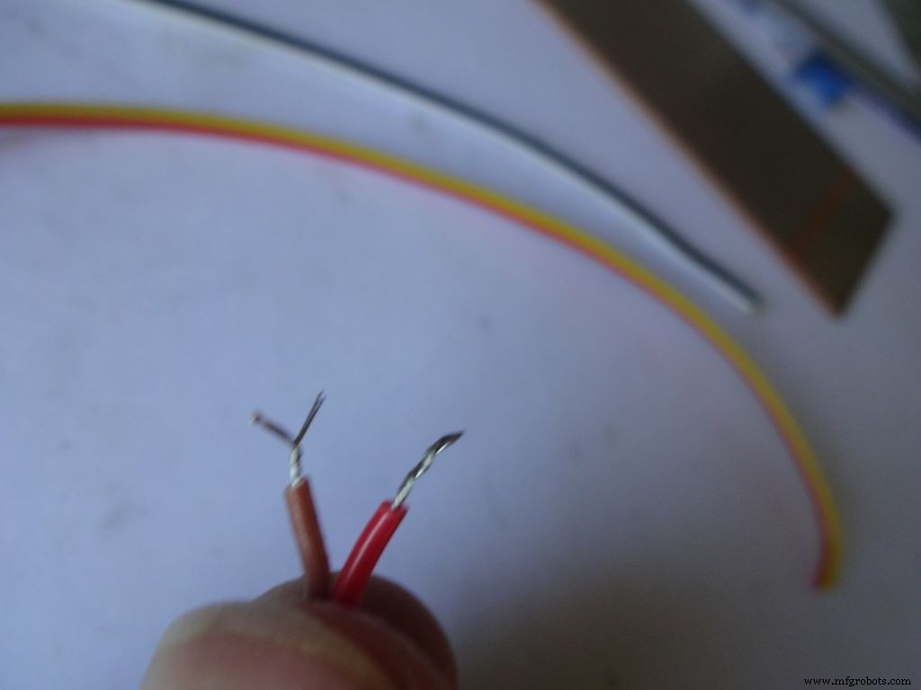
Pele una pequeña parte del aislamiento (no más de 5 mm) y retuerza los hilos.
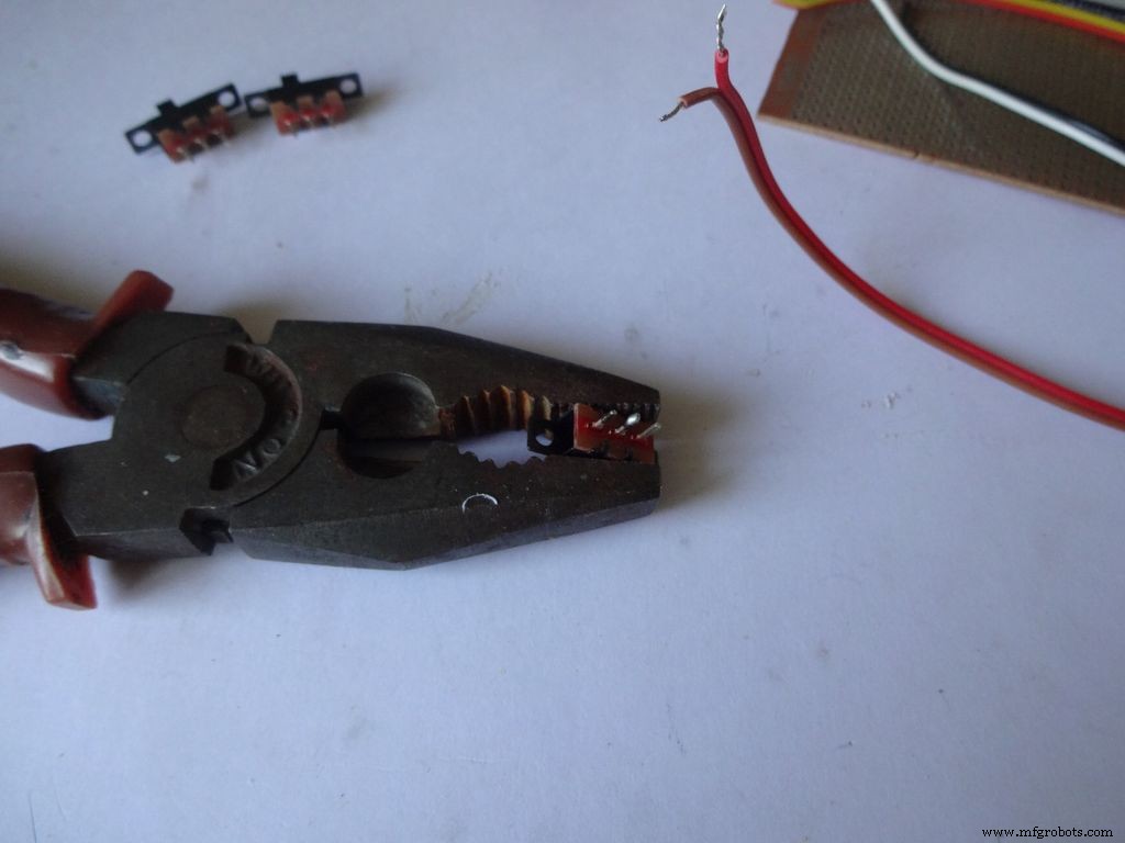
Aplique un poco de soldadura a 2 pines adyacentes de cada uno de los interruptores. Use algo para mantenerlo en su lugar mientras suelda, usé un alicate pesado.
Si no ha soldado antes, ahora es un buen momento para comenzar. Youtube tiene toneladas de videos sobre cómo soldar correctamente. Las lecciones de PACE son muy informativas, míralas.
A continuación, tenemos que "estañar" los cables. Toque con la punta del soldador el cable a estañar. Aplique un poco de soldadura entre la punta y el cable, esto crea un puente que conduce el calor desde la punta al cable. Luego, aplicas soldadura directamente al cable, en el lado opuesto de la punta del soldador . Retire la soldadura. Retire la punta. Un video sobre esto.
Después de eso, mantenga el interruptor en su lugar, lleve uno de los cables entintados al pin y refluya la soldadura tocando el soldador. Haz lo mismo con el segundo cable. Observe que coloco los cables de color oscuro a un lado de los interruptores.
Ahora repita el procedimiento y conecte dos cables a un botón (este será el botón de reinicio). Asegúrese de no colocar cables en los extremos normalmente conectados del botón.
Paso 8:Hacer el caso - Cortar el diseño
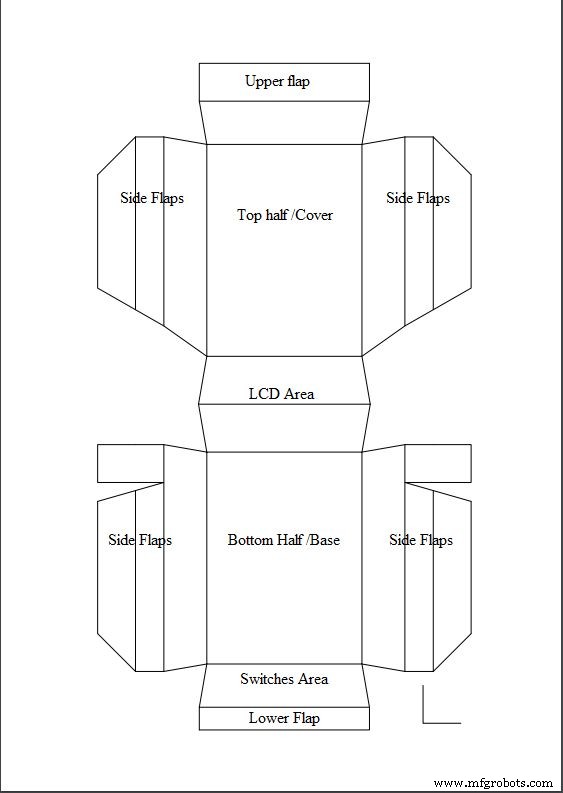
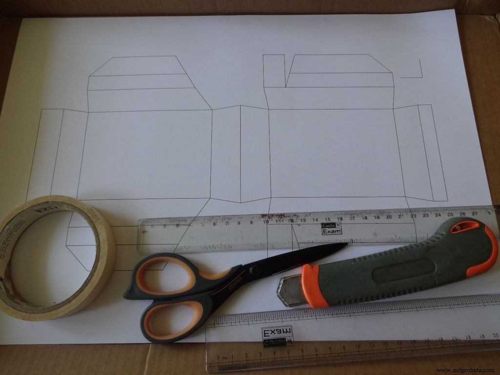
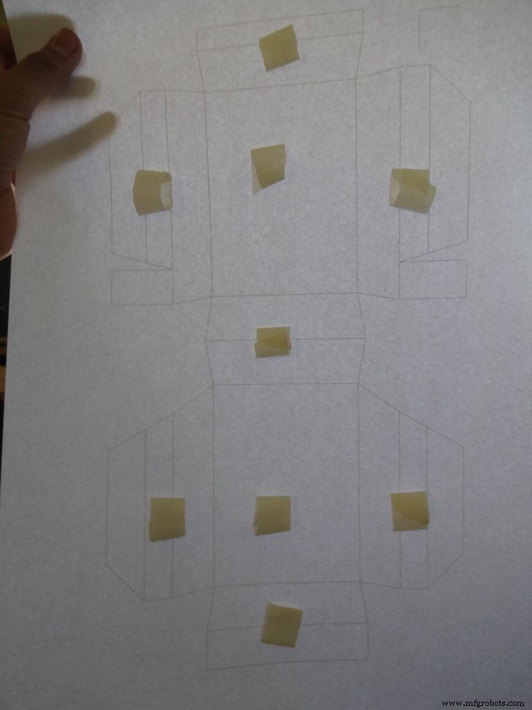
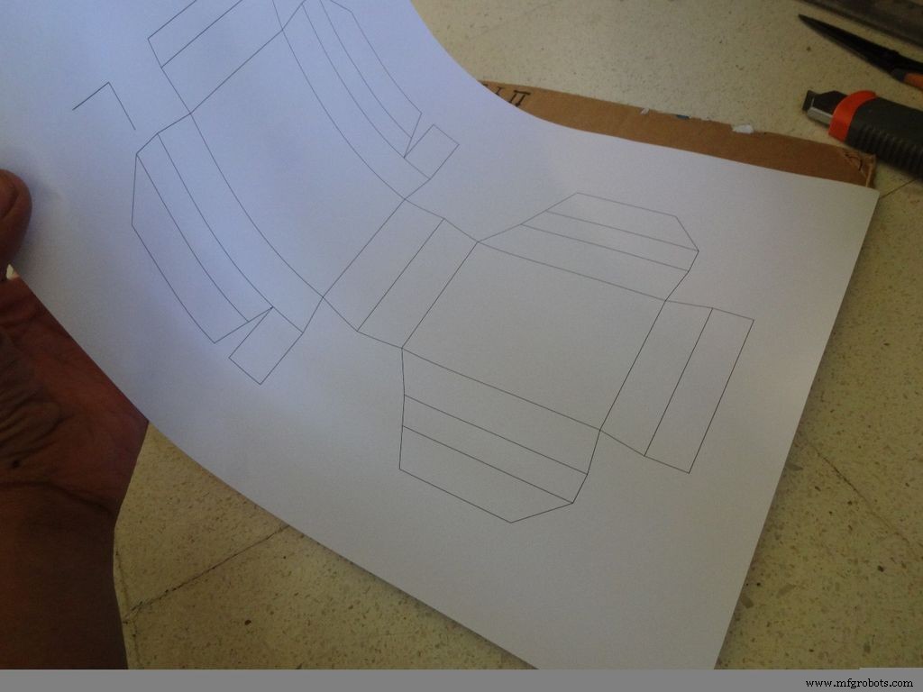
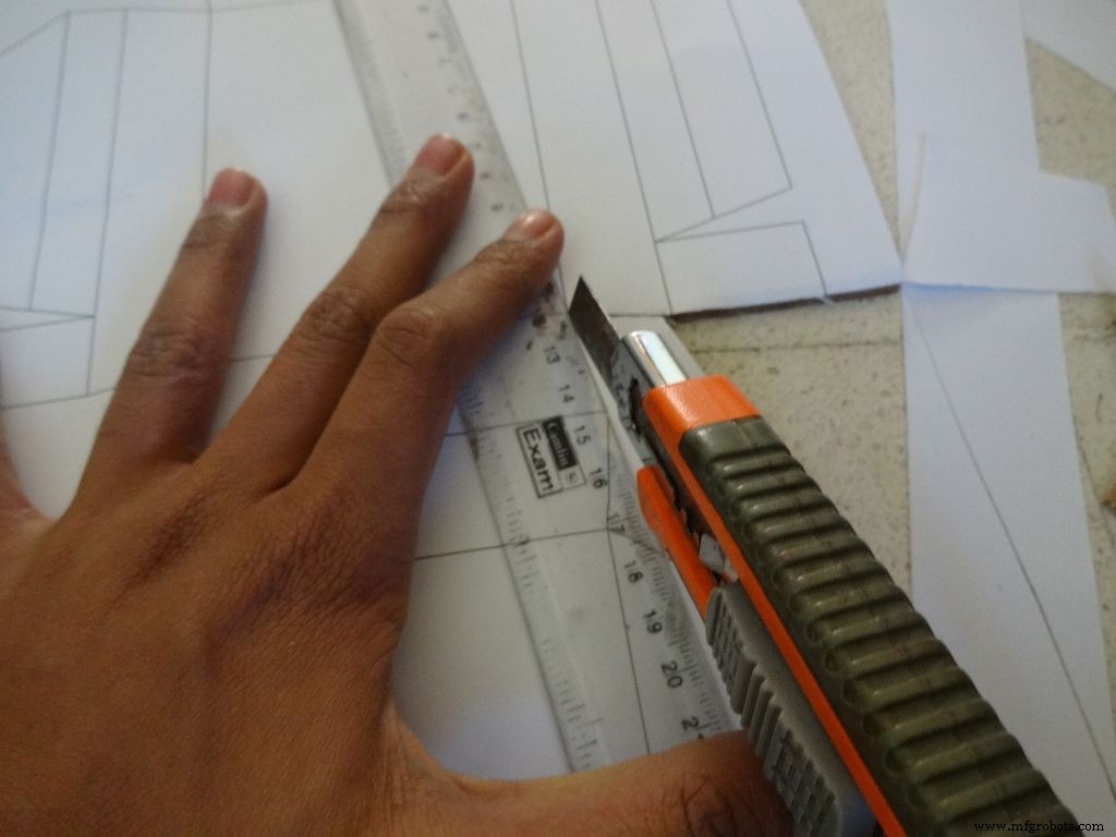
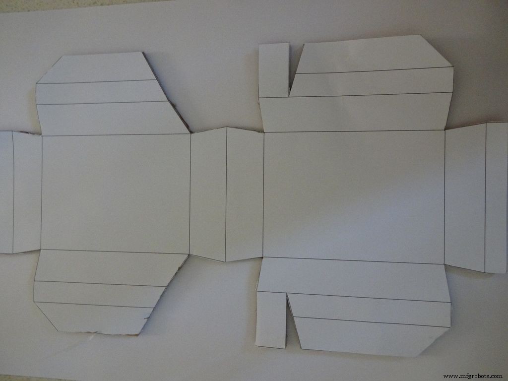
Descargue "Layout_Final_A3.pdf" o "" Layout_Final_ANSI_B.pdf ", según el tamaño de papel disponible en su región, adjunto al final.
Imprima en un papel de tamaño A3 (29,7 x 42,0 cm o 11,69 x 16,53 pulgadas) o la alternativa ANSI B de EE. UU. (11 x 17 pulgadas o 279 × 432 mm). Asegúrese de que, al imprimir, seleccione el tamaño de papel y la orientación adecuados y seleccione la opción "Tamaño real". Confirme que la impresión es precisa midiendo el pequeño ángulo recto en la esquina inferior derecha, debe ser de 2 cm x 2 cm.
Corta un trozo de cartón aproximadamente más que el diseño. Rasgue un pequeño trozo de cinta, forme un rollo de 'doble cara pegajosa' y péguelo en los lugares que se muestran. Luego pegue la hoja en el cartón.
Utilice unas tijeras afiladas o un cúter con una regla para cortar el límite exterior del diseño de la caja. Encontré los cortadores de cajas mucho mejores que las tijeras. La mayoría de los cortadores tienen cuchillas que se pueden romper en etapas para obtener una punta fresca y afilada, por lo que se recomienda hacerlo. Mantenga otro trozo de cartón o madera debajo de la parte que está cortando, esto ayuda a obtener cortes más limpios.
Además, no mantener la regla correctamente sobre la línea mientras se corta es un error común. No hagas esto con prisa.
Paso 9:Confección de la carcasa:plegado y plegado
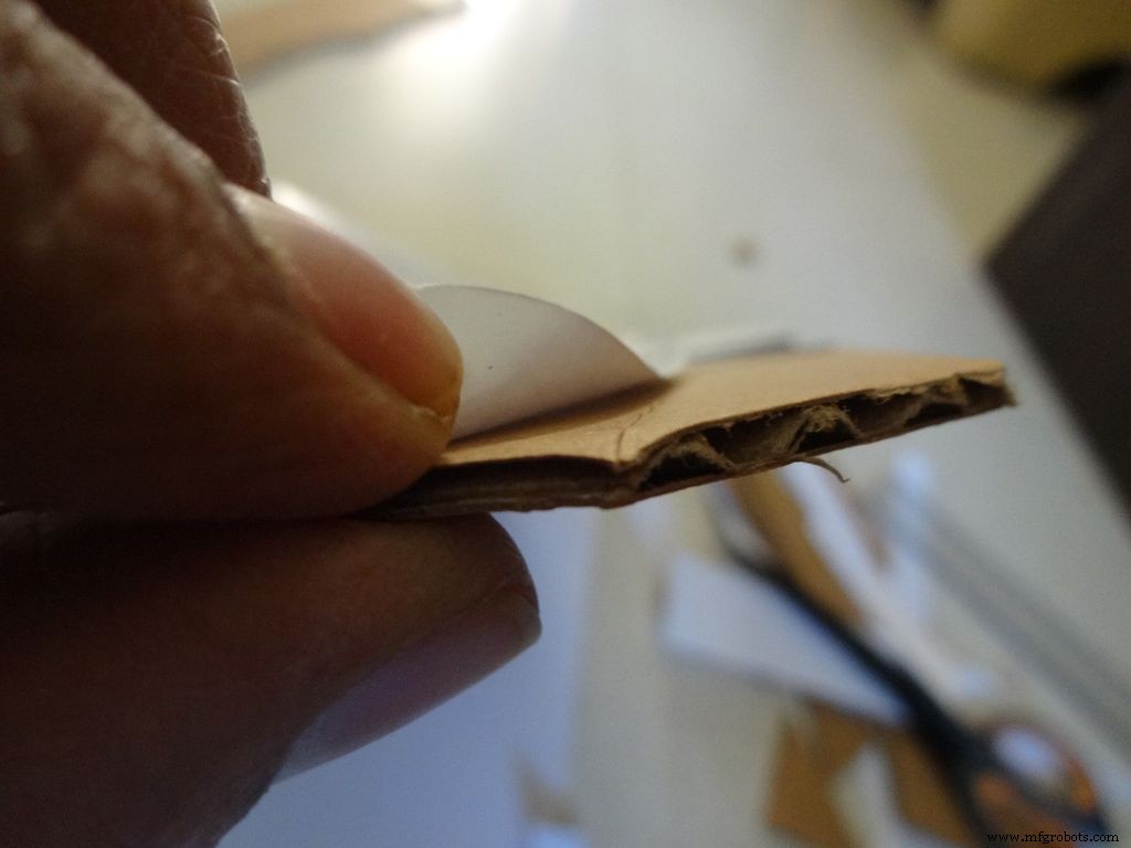

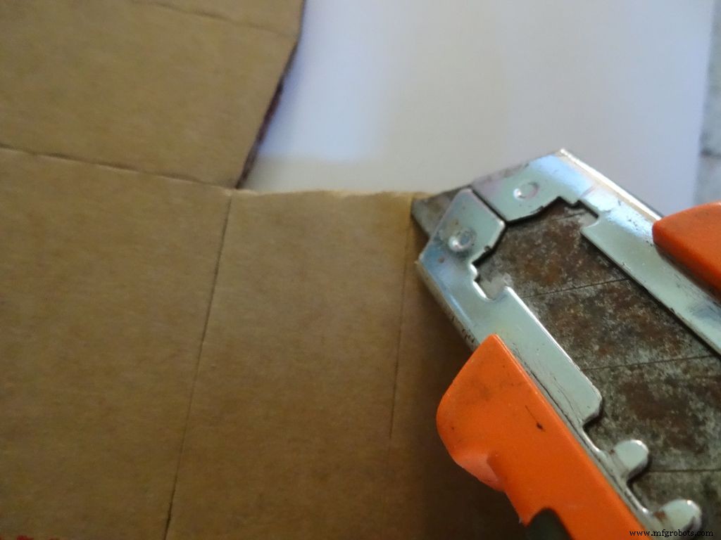
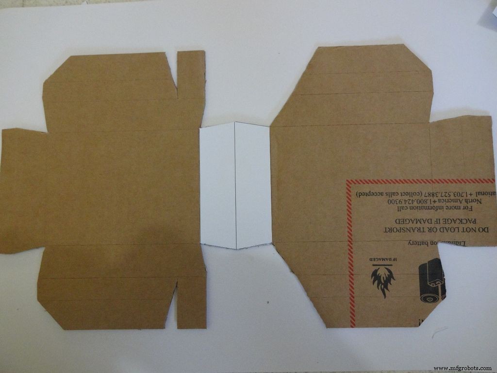
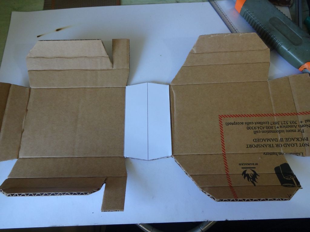
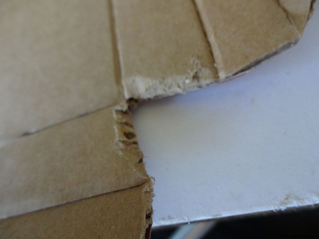
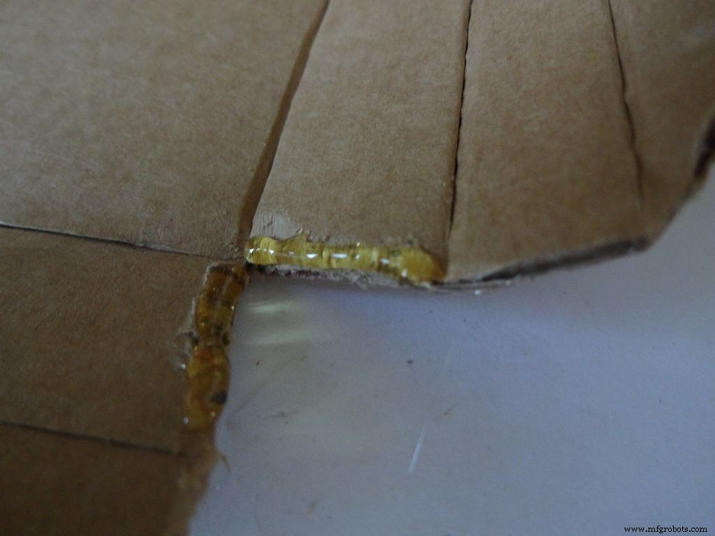

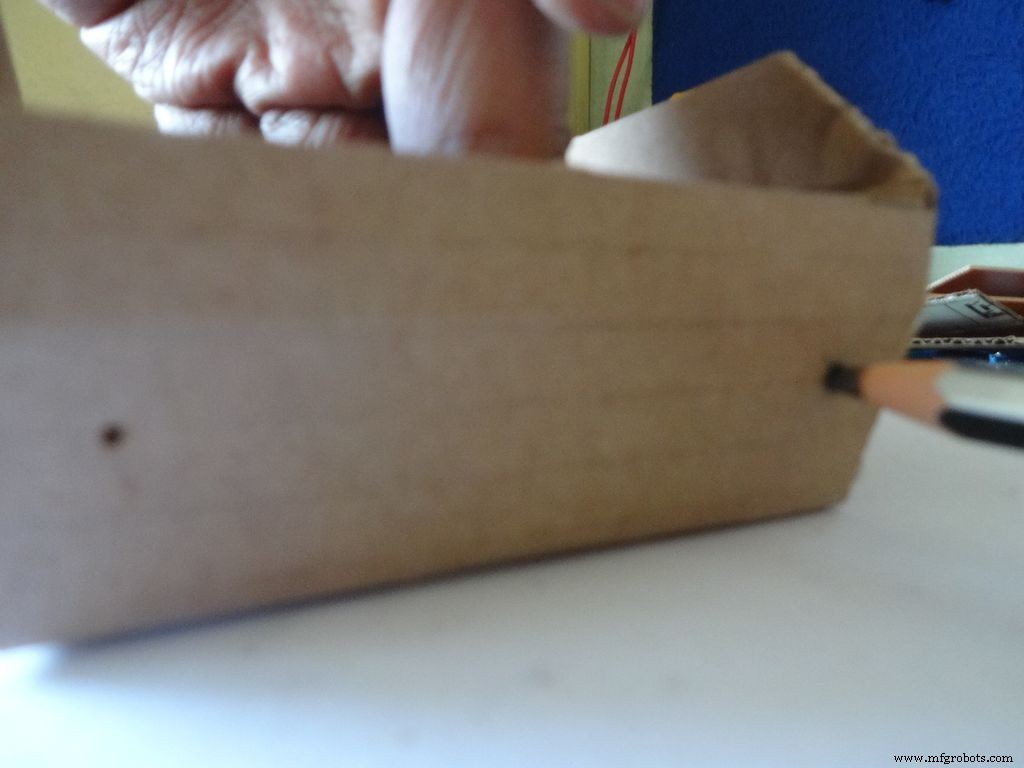
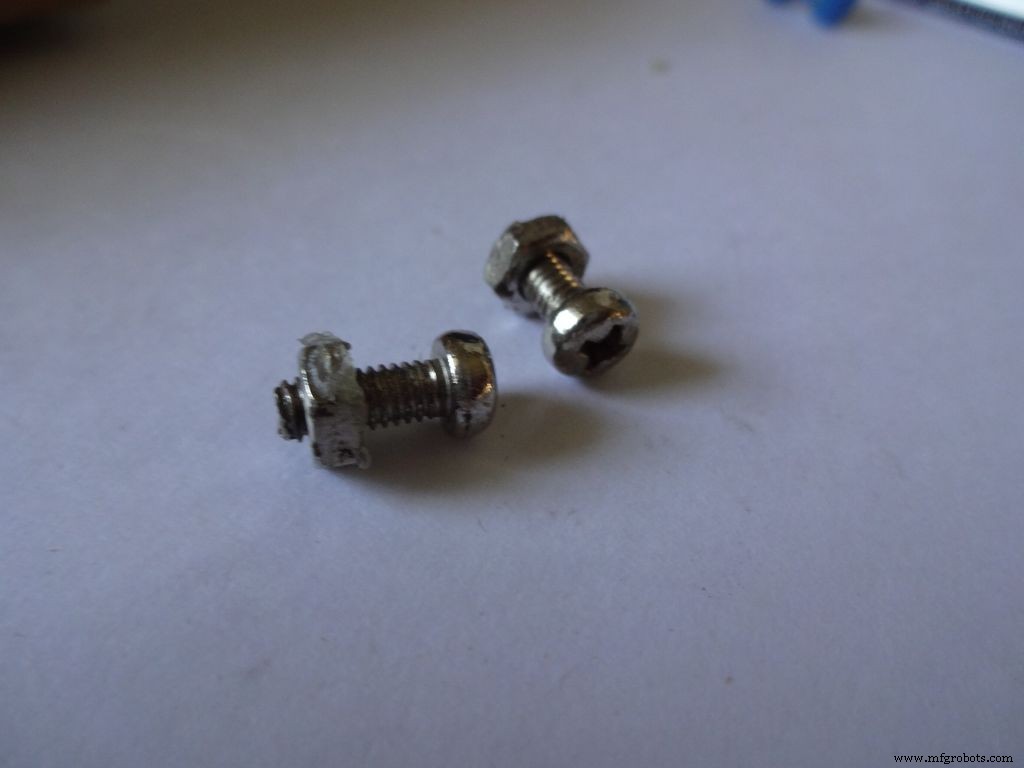
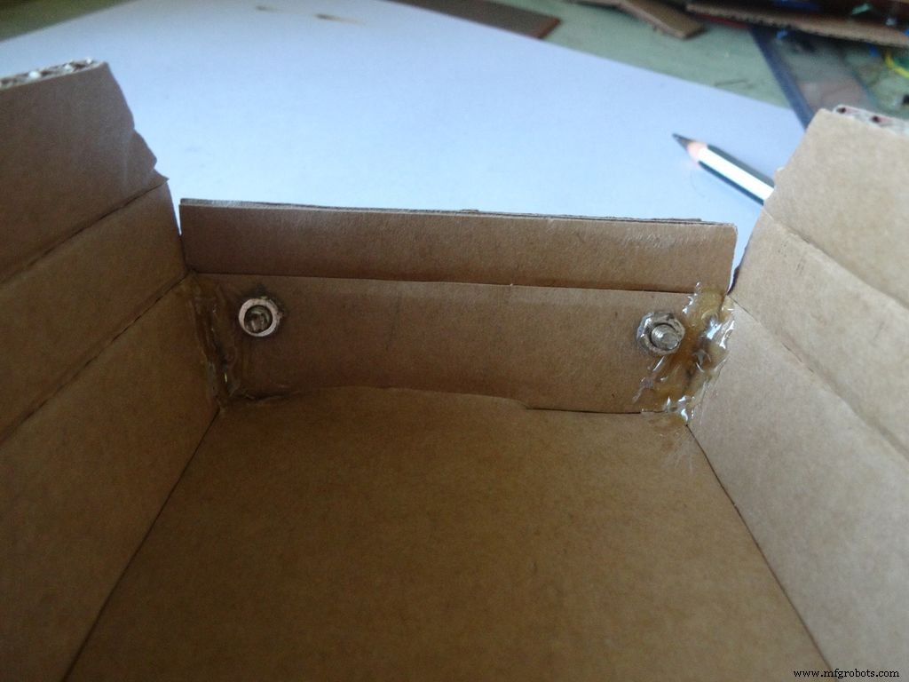
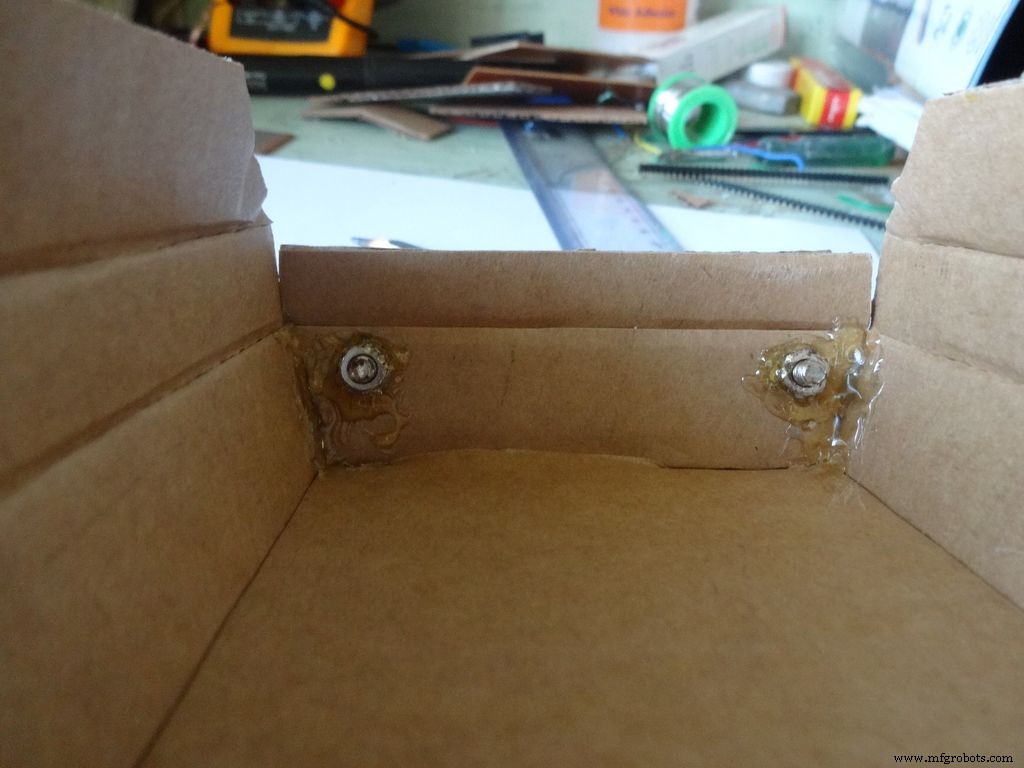

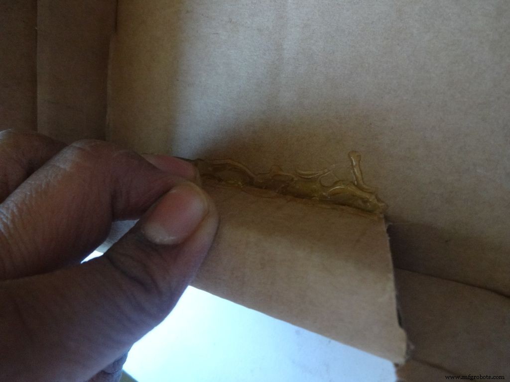
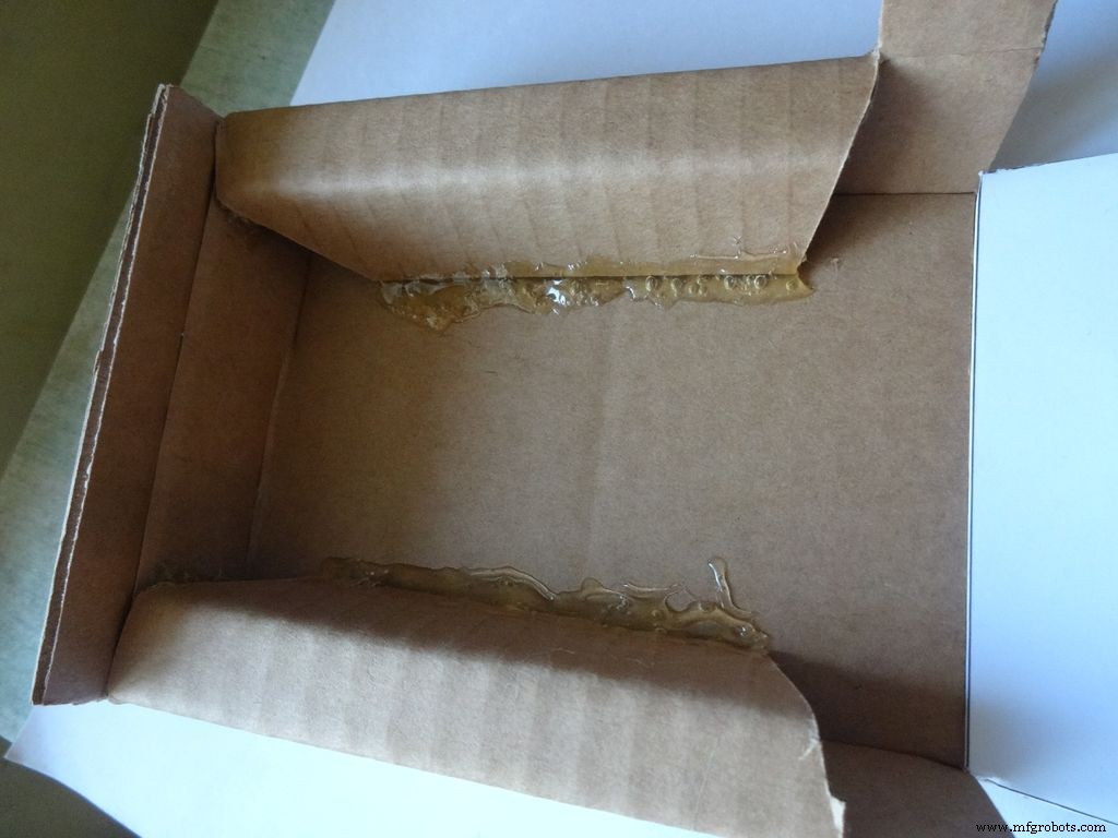
Con el cortador con la escala, haga con cuidado los pliegues a lo largo de todas las líneas de plegado, excepto la línea media en el área de la pantalla LCD. Doble y doble todas las partes plegables y rectifique las arrugas incompletas.
Para la mitad inferior o base:
Usando el papel de lija, lije los primeros cuatro bordes en una pendiente, aplique pegamento caliente con una pistola de pegamento (un lado a la vez), únase y mantenga durante 30-60 segundos mientras el pegamento se enfría.
Haga dos agujeros con un alfiler como se muestra y agrande con un lápiz lo suficiente para que encaje el perno. Apriete la tuerca en el interior, aplique pegamento caliente (¡solo en la tuerca!), Déjela enfriar. Quite el perno con un scredriver.
A continuación, doble las dos solapas laterales hacia adentro y péguelas. La parte exterior de la solapa debe estar ligeramente inclinada y la parte media plana.
Paso 10:Hacer el caso:agregar los interruptores
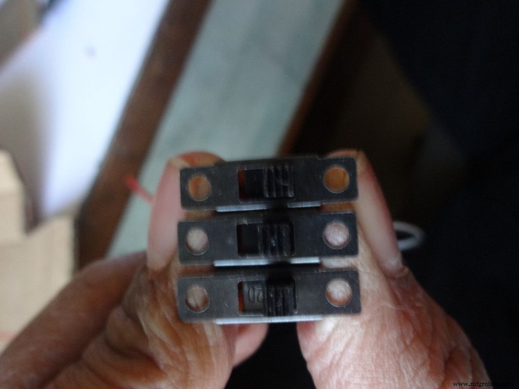
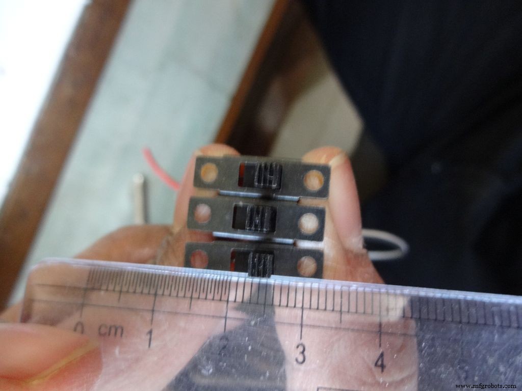
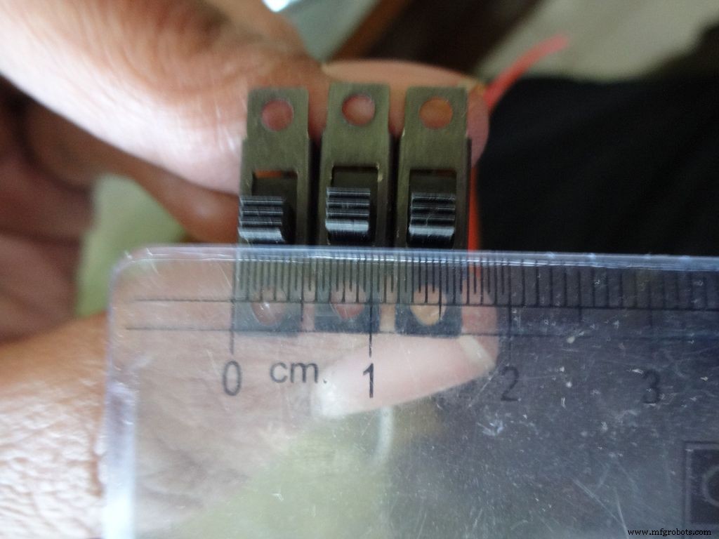
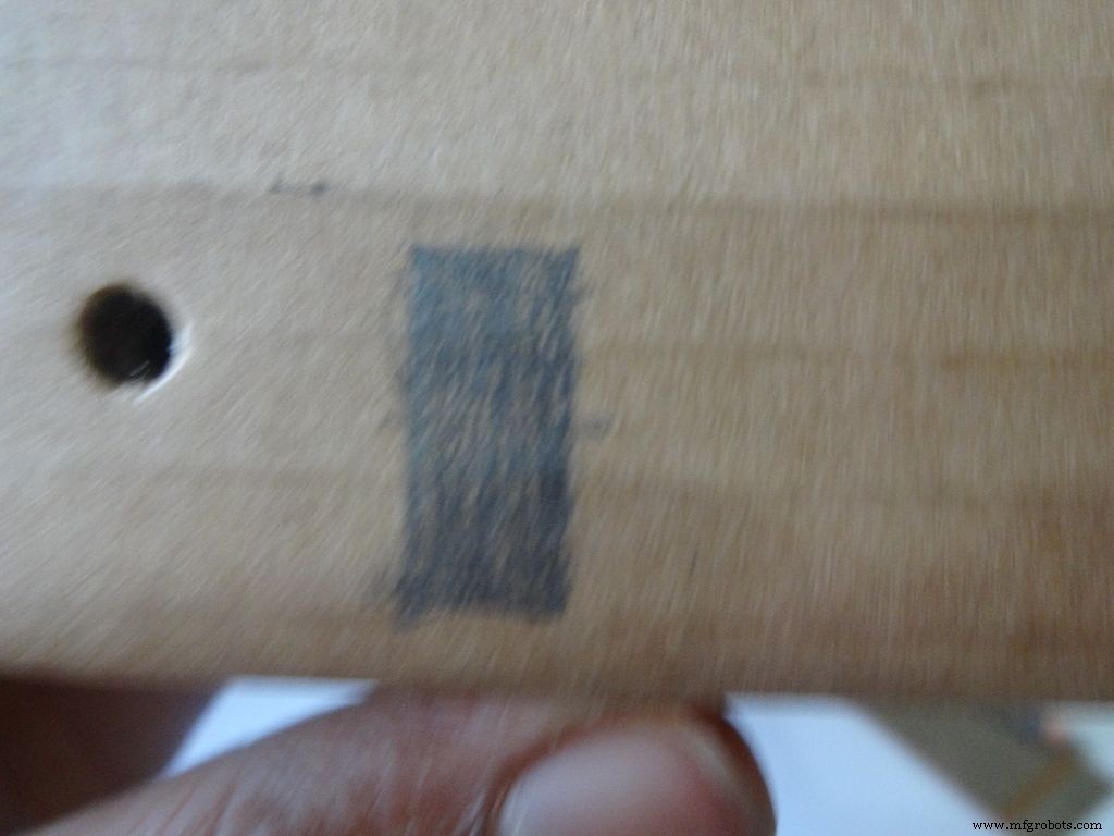
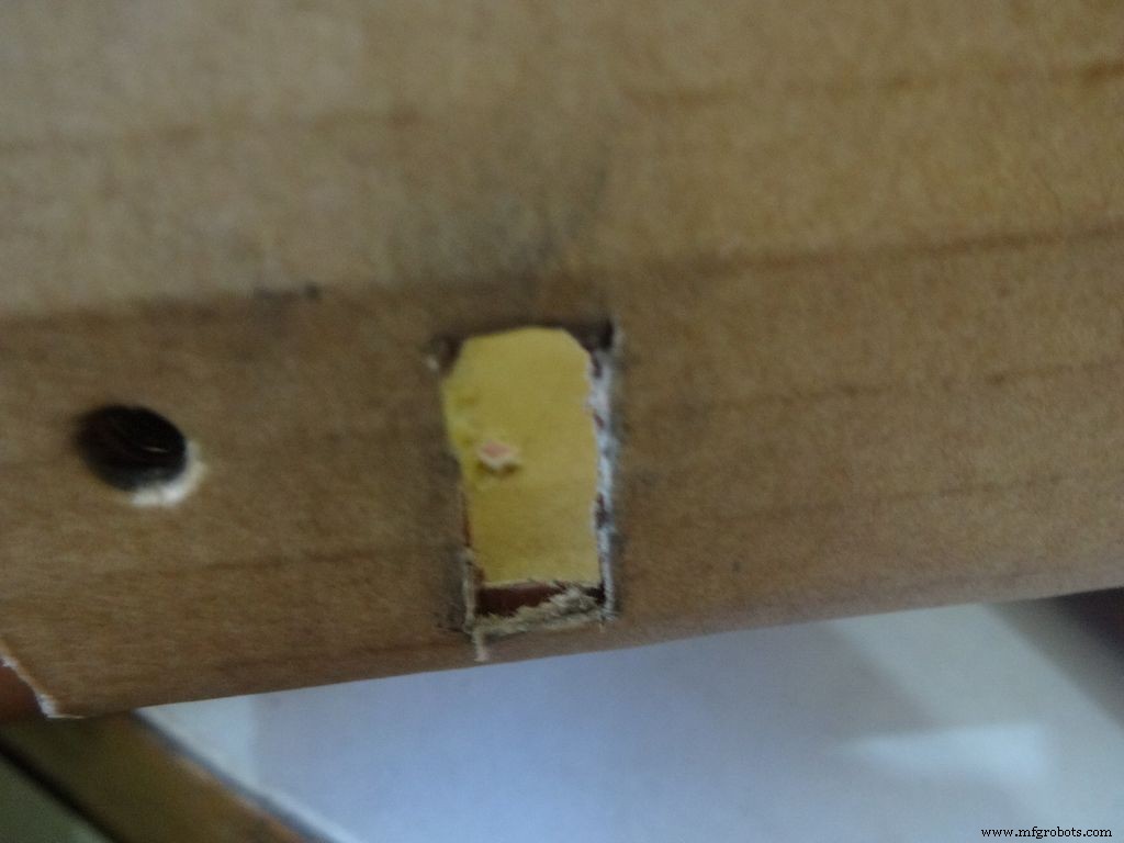
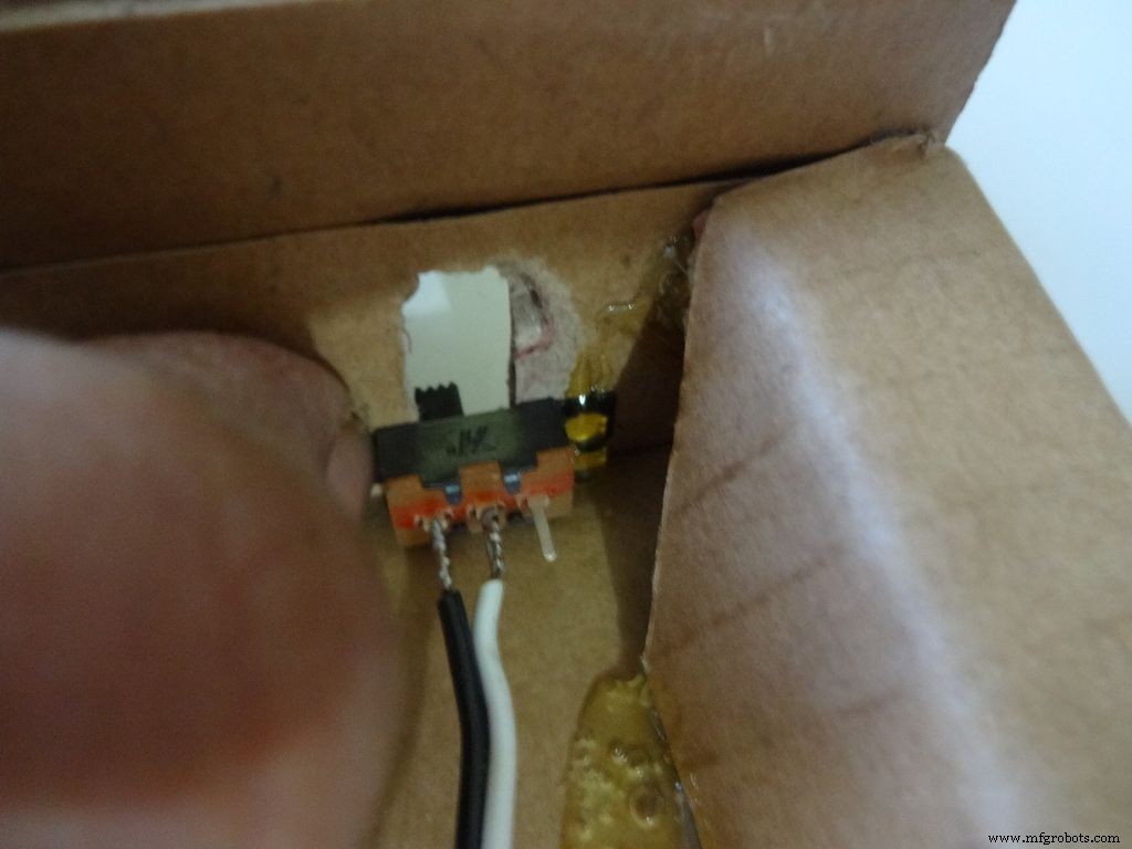
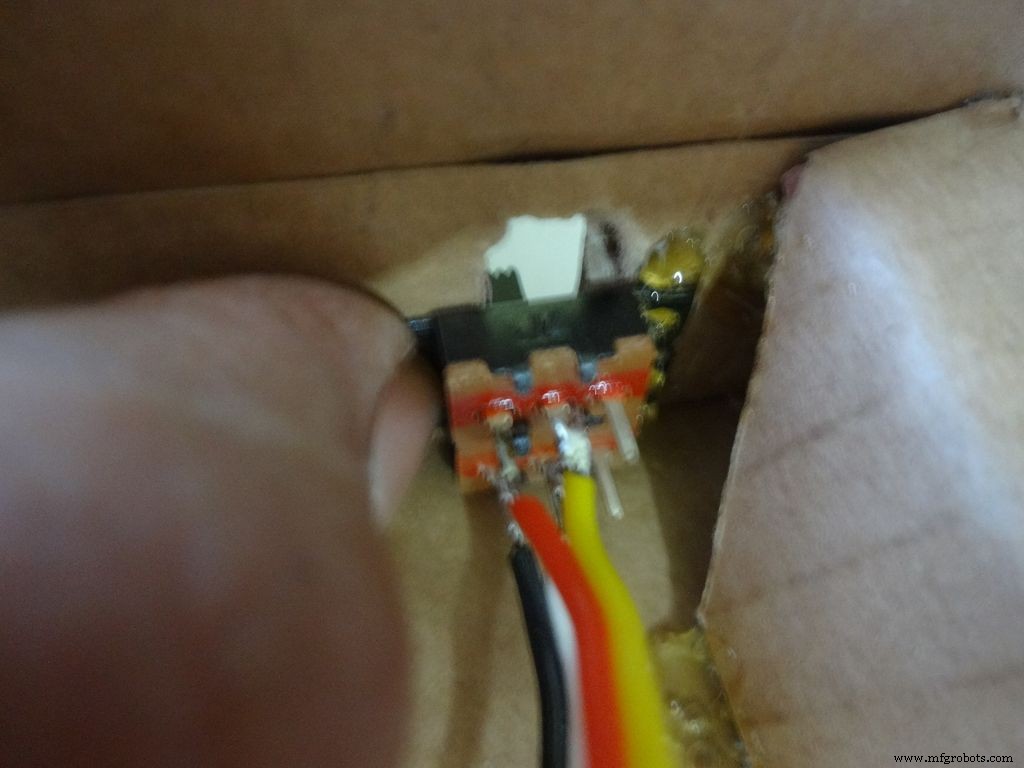
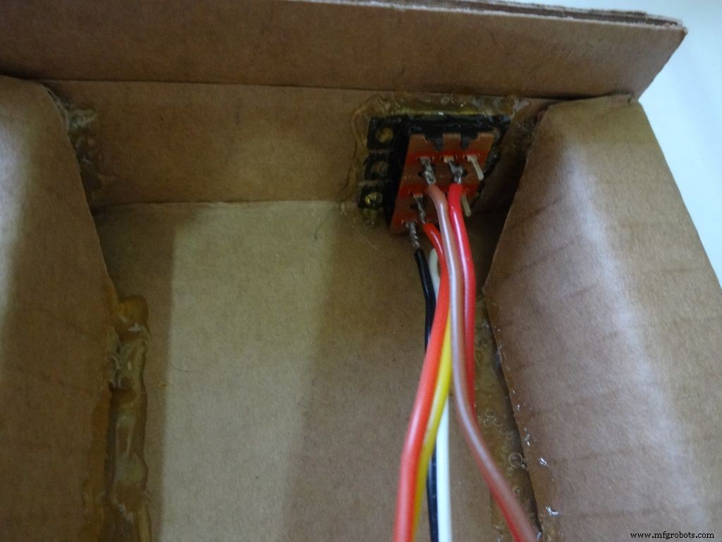
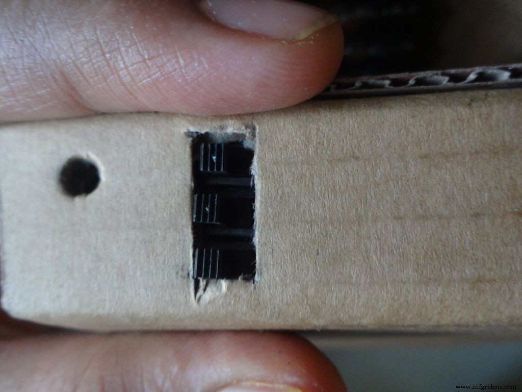
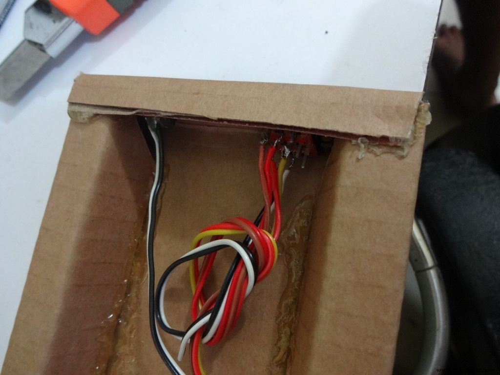
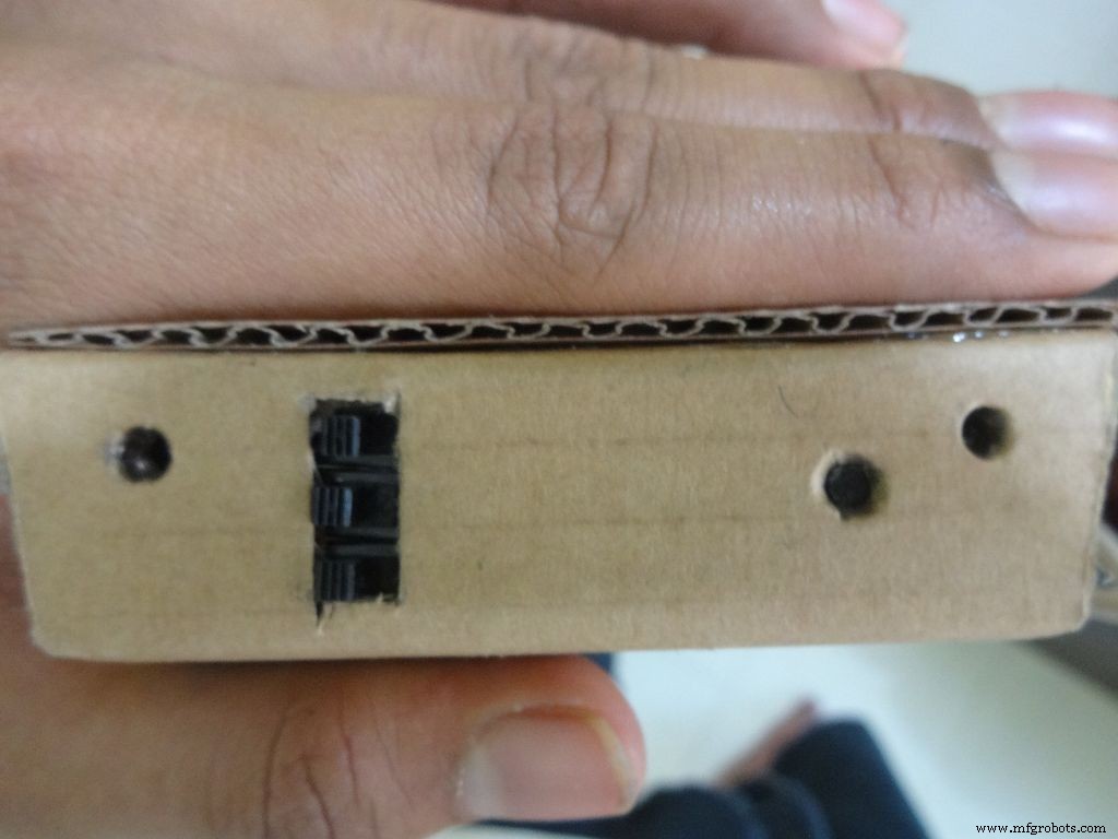
Take the 3 sliding switches with wires we soldered earlier, measure the approximate dimension of rectangle needed. Mark it on the left side of the box(left from the outside). Cut it with a cutter, sand it a bit on the inside to remove any material sticking out.
Keep the first switch in position and while holding it add glue on one side. Let it cool. Repeat with the other two as well, and then add glue on the remaining sides. Note:The wired pins of the switches should be on the same side.
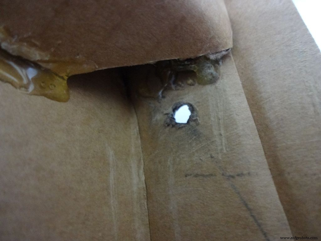
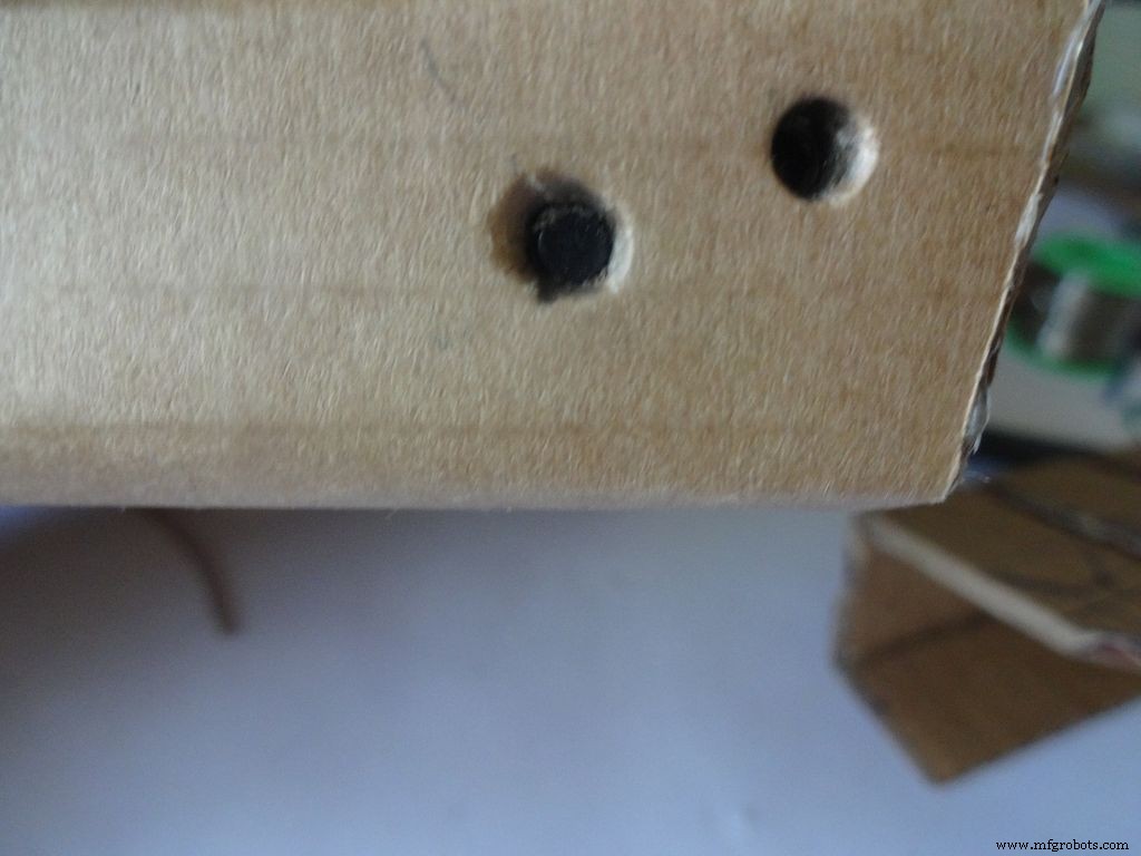
Make another hole on the other side for the reset pushbutton. Hold the button in place and add glue. Fold the lower flap inwards and stick it.
Step 11:Making the case - Top half or cover
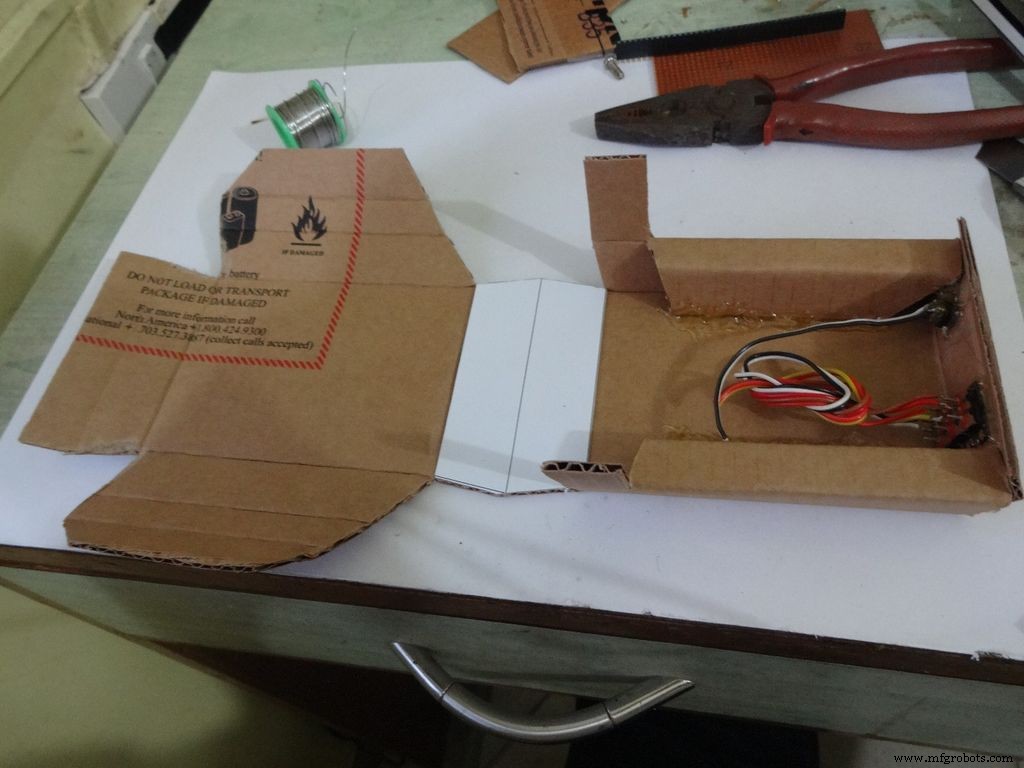
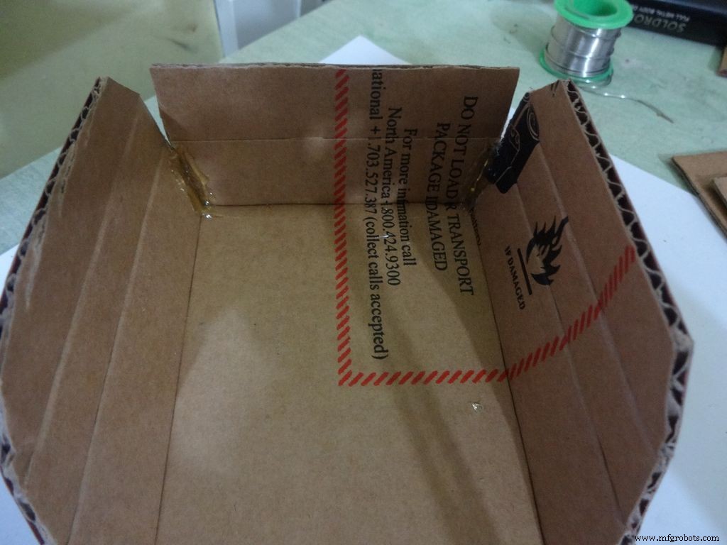
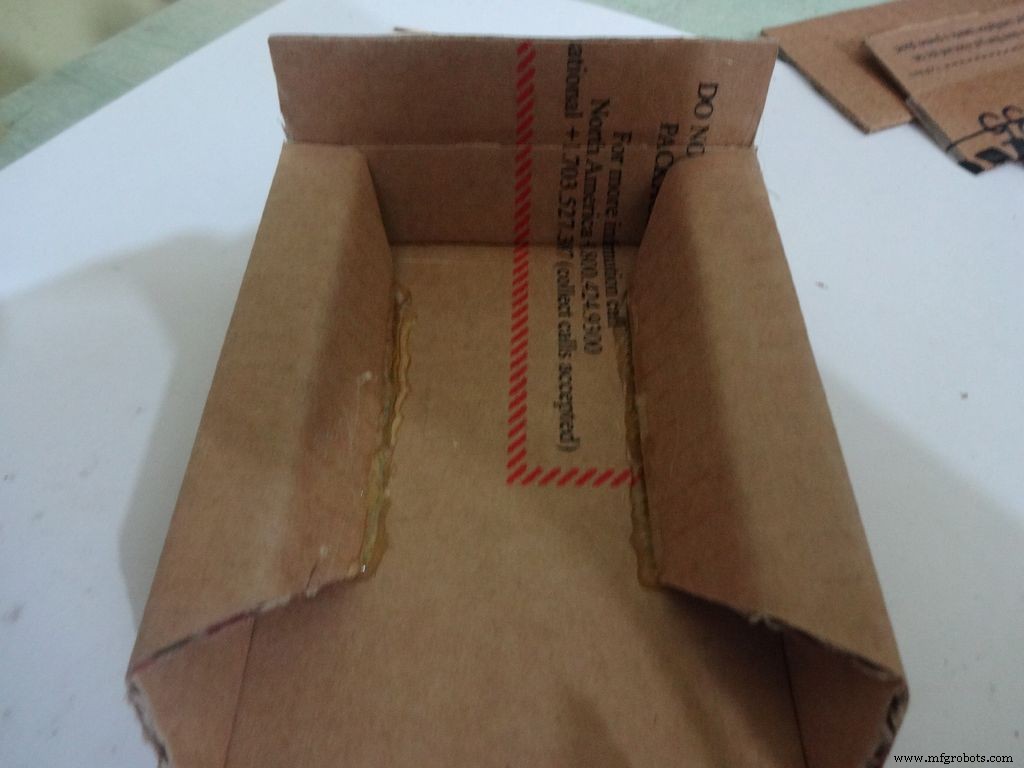
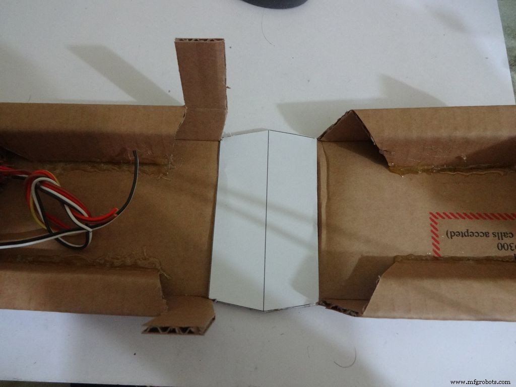
Sand the edges and stick the side flaps inwards(just like the base) for the top half
Step 12:Making the case - Adding the LCD
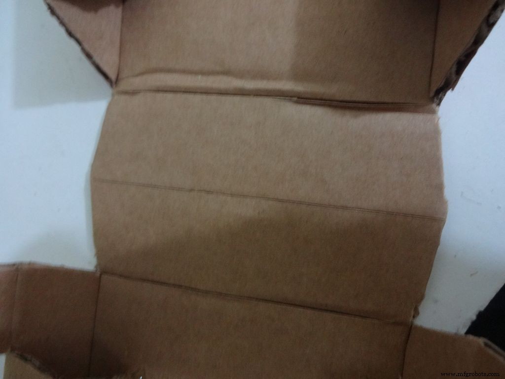
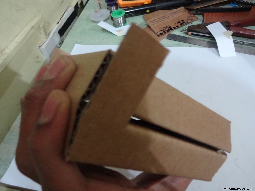
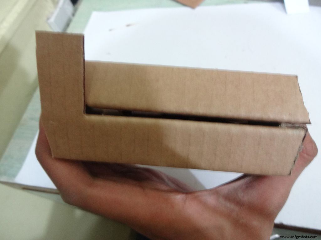
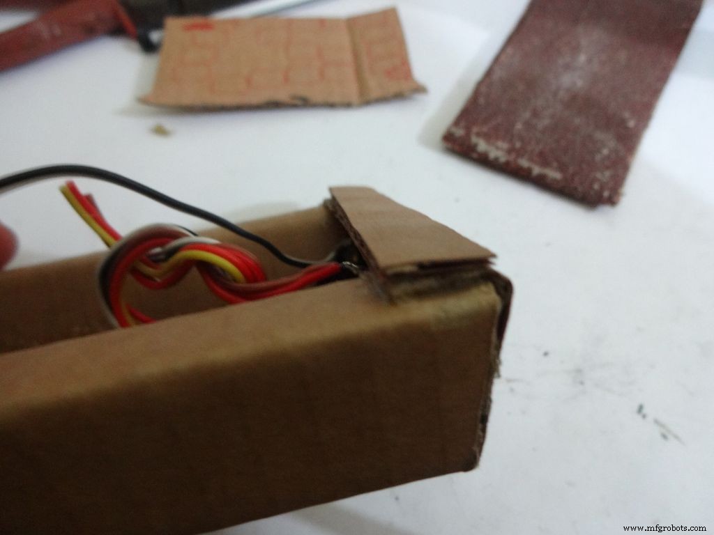
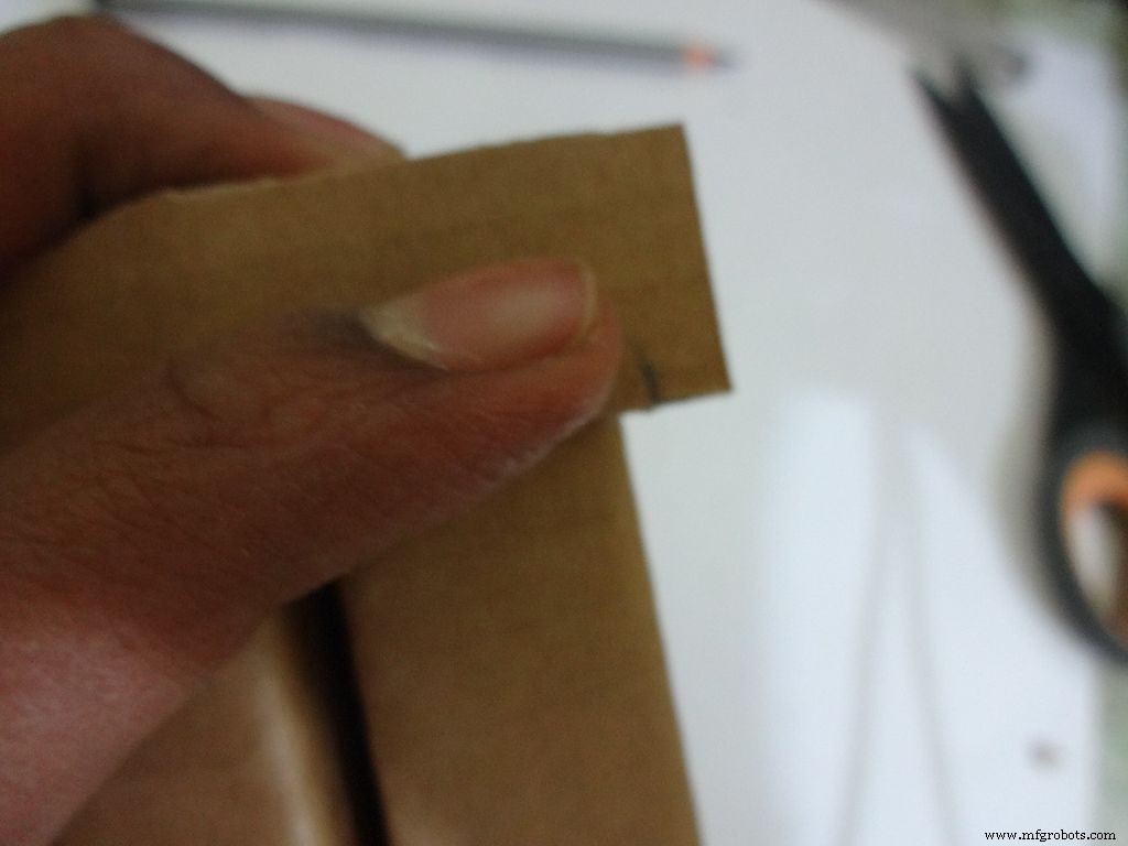
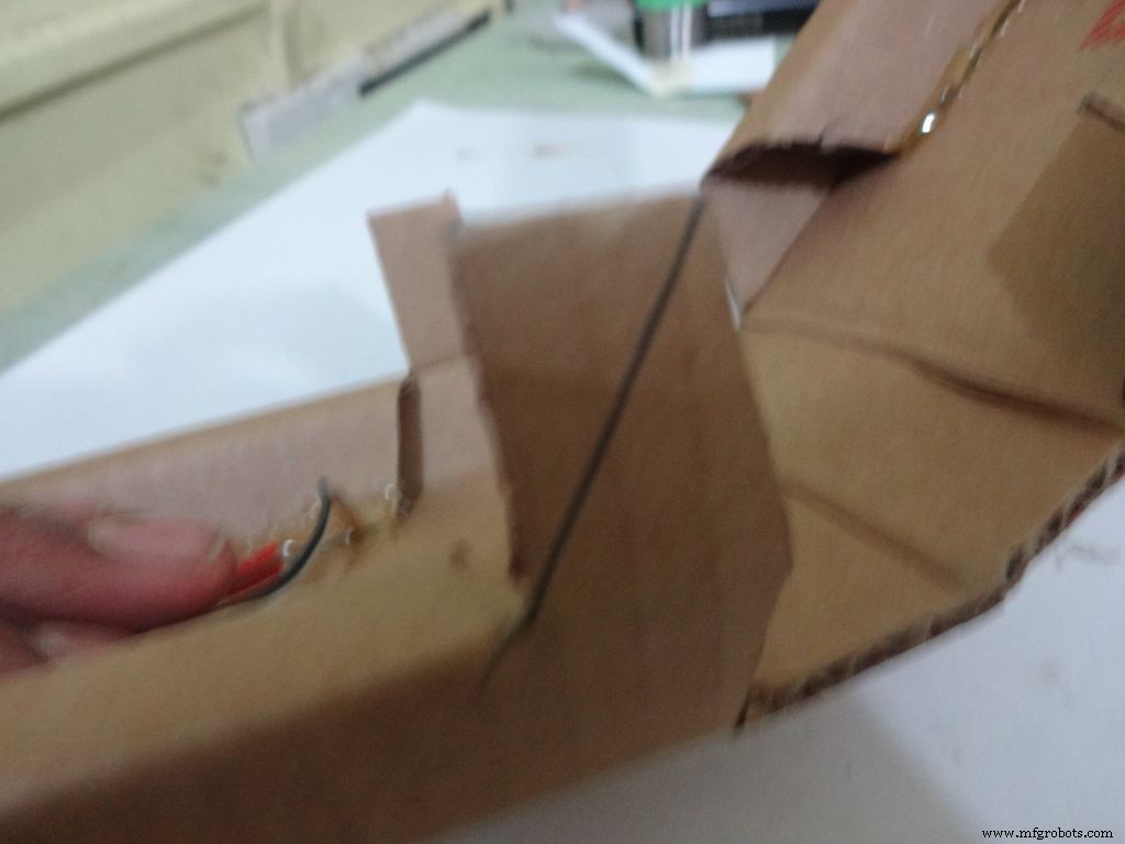
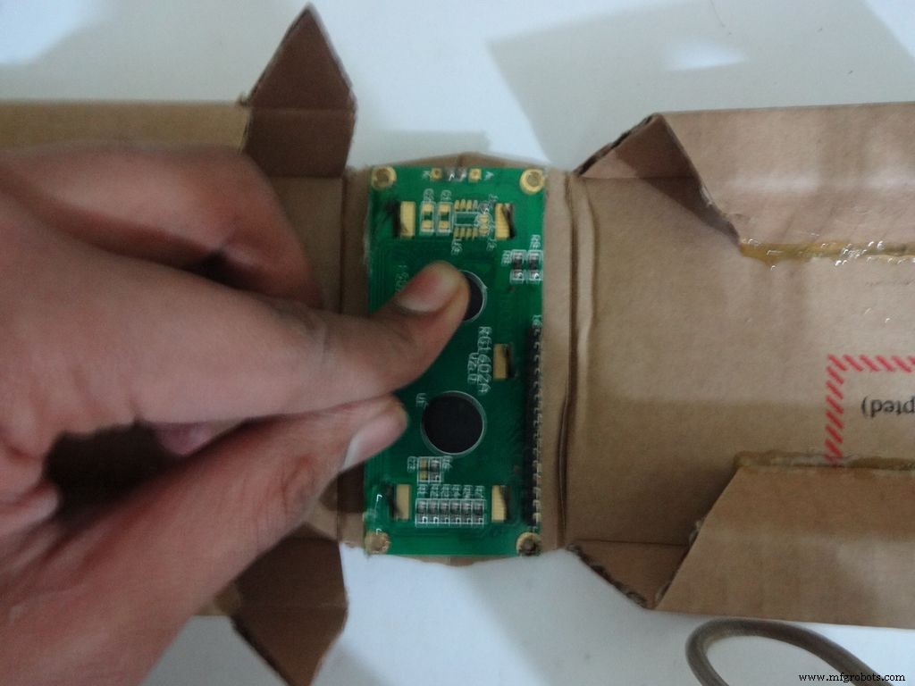
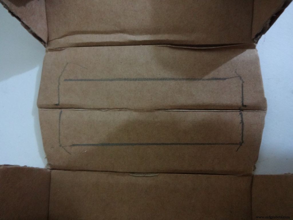
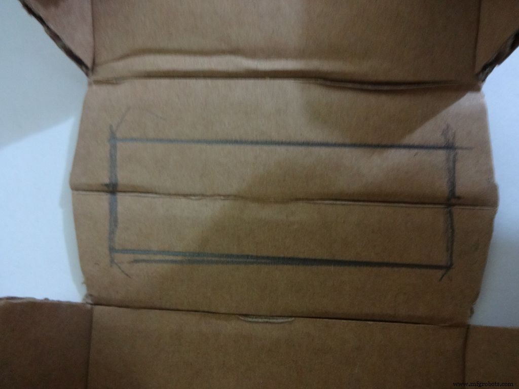
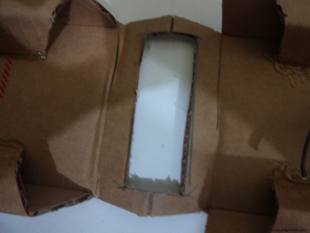
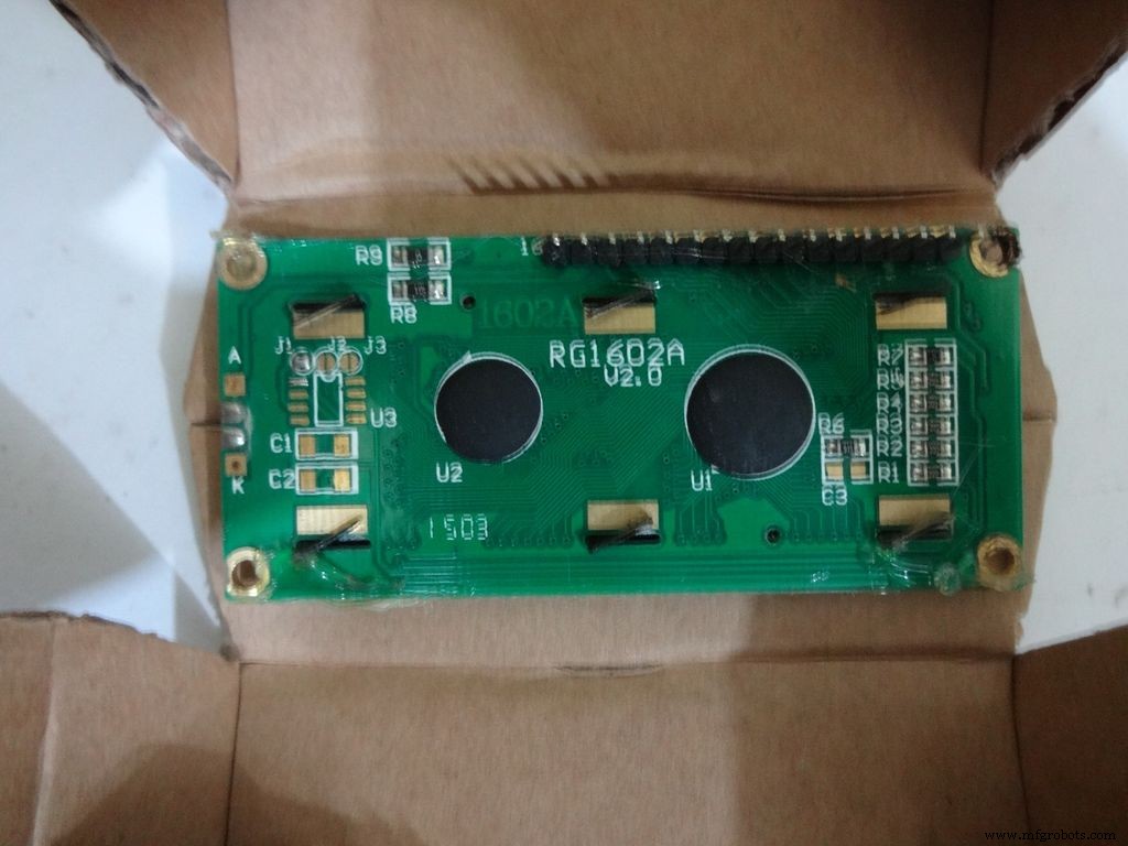
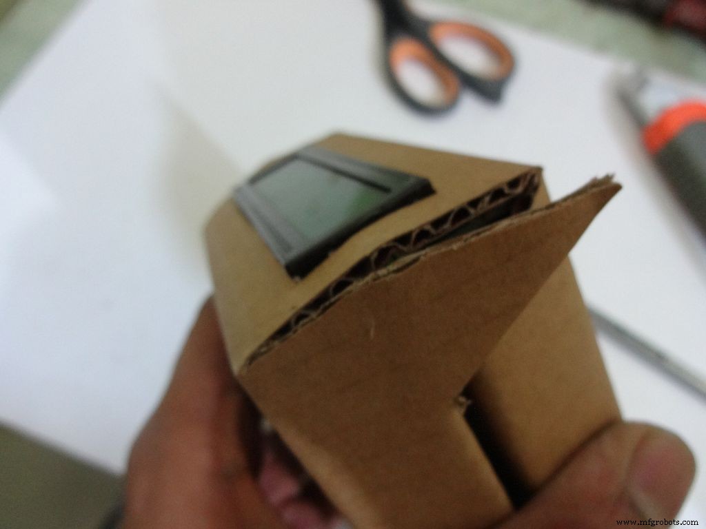
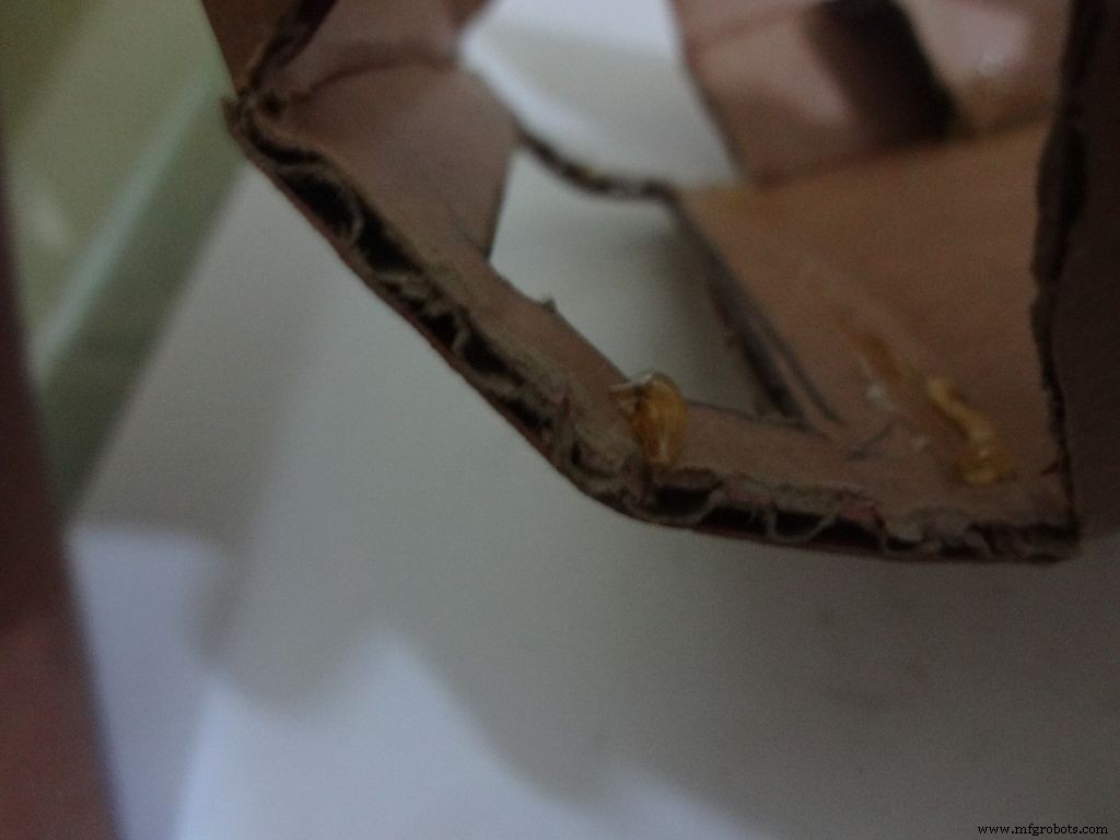
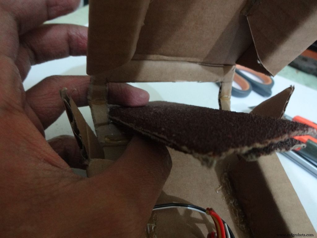
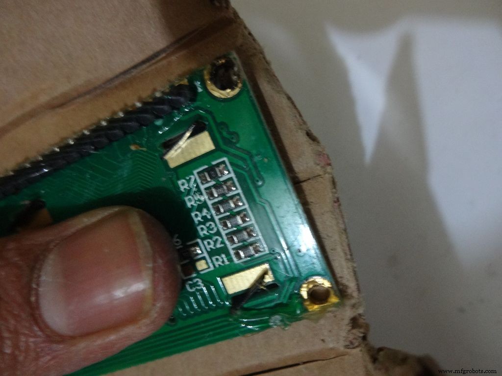
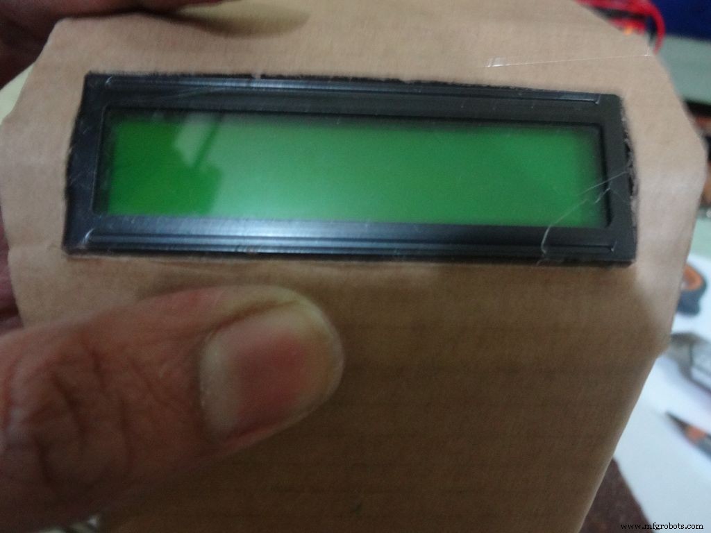
Crease the middle line. (Didn't do it earlier as it is delicate and gets loose soon).
Fold the cover over to the base and check whether everything looks alright, sufficient spacing should be left for the IC pins. (See photo)
Cut the covering flaps as shown in the images.
Keep the LCD at the center of the LCD Area, mark it with a pencil. Using a ruler, make the rectangle properly and cut it carefully using a cutter. Fold the LCD window and apply glue to the hinges to keep them at their correct position. Insert the LCD and make any modifications if required.
Finally, apply glue to the four corners(don't put excess) of the LCD and place it in position.
Step 13:Making the case - Final flaps
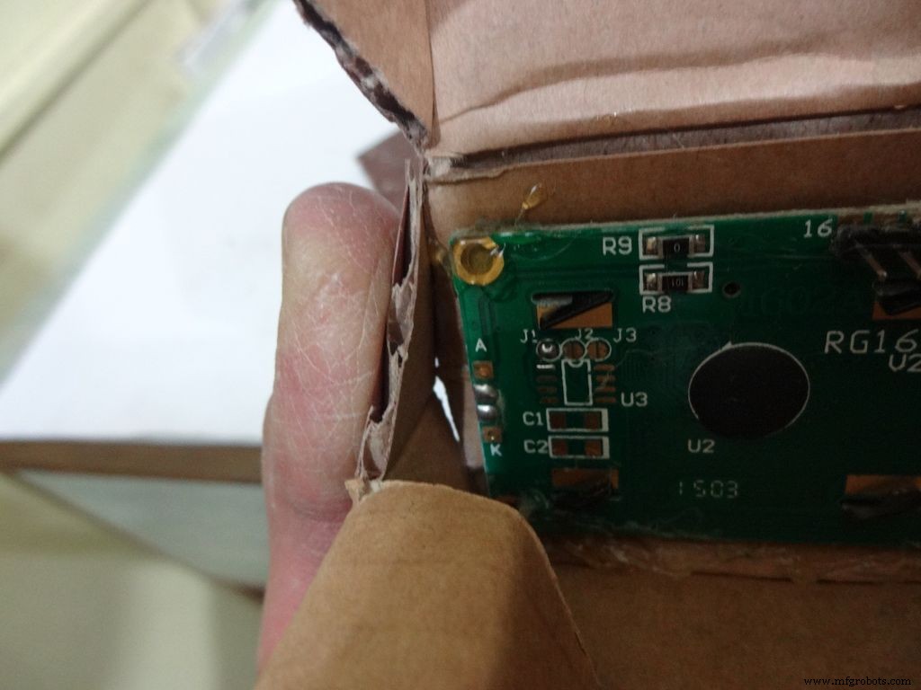
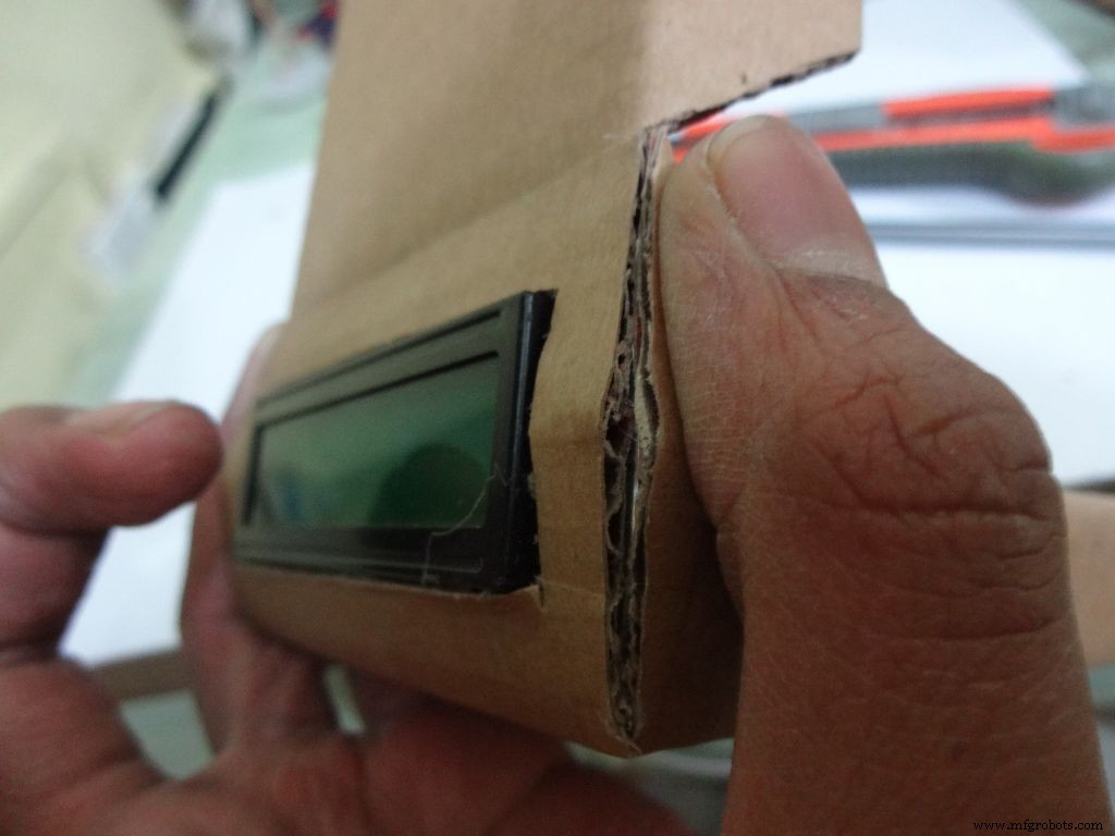
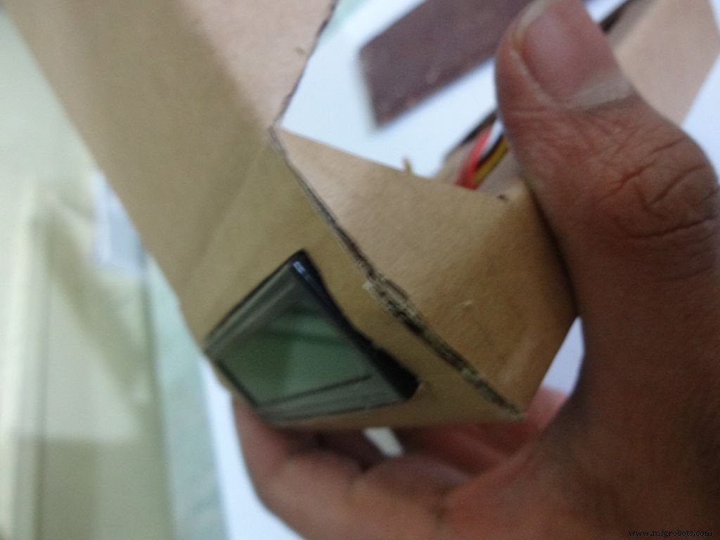
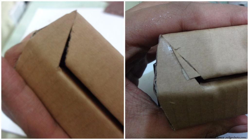
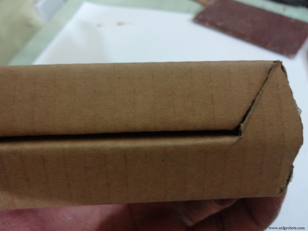
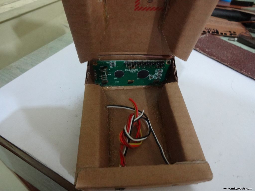
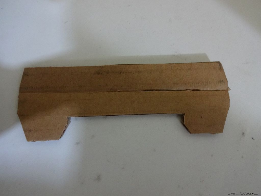
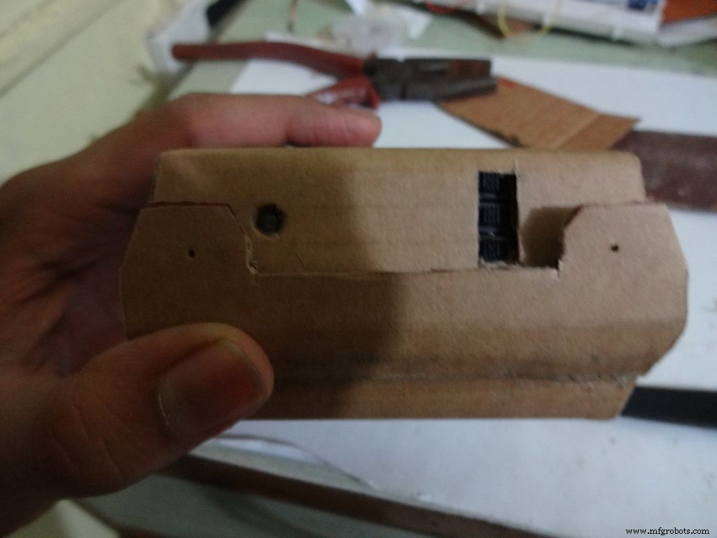
Sand, trim and close the tringular flap.
Make a small piece as shown and stick it to the cover. Make two holes, widen them with a pencil for inserting the bolt and locking the cover to the base.
Step 14:The Circuit Board -- Making it fit

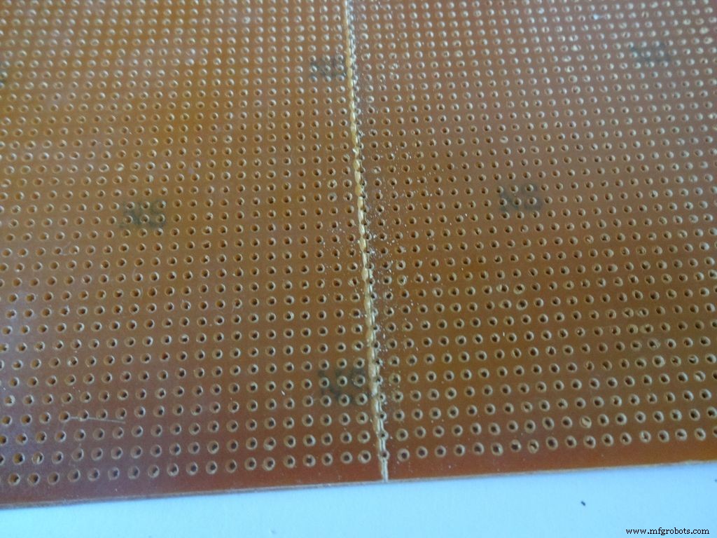
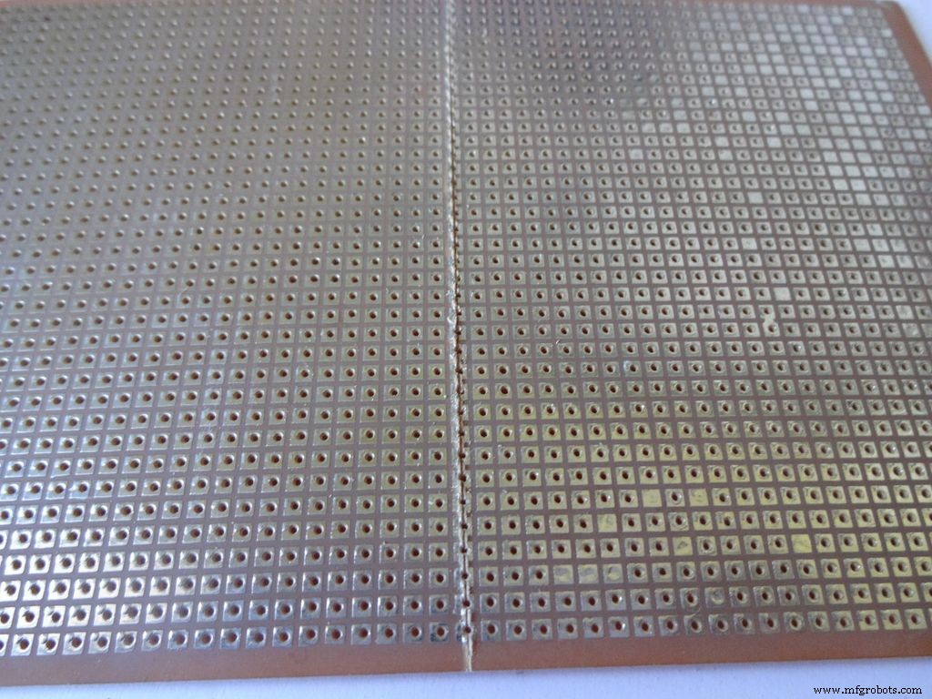
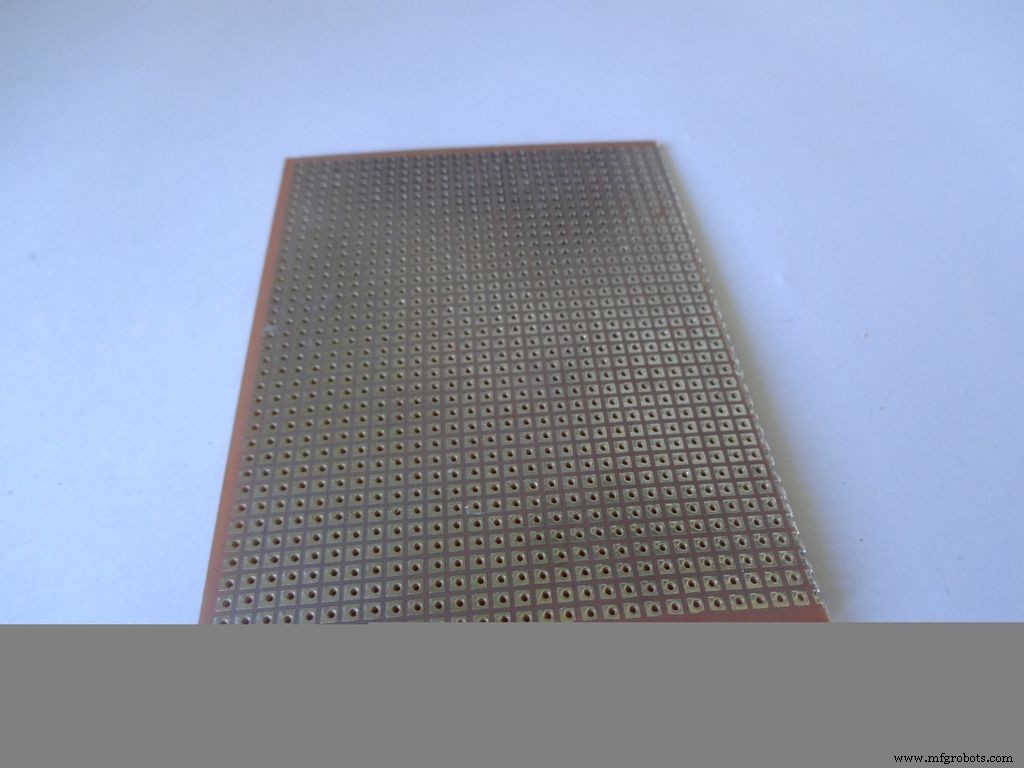
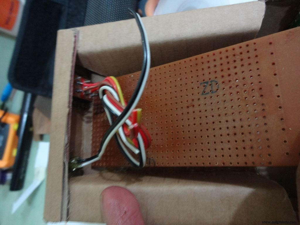
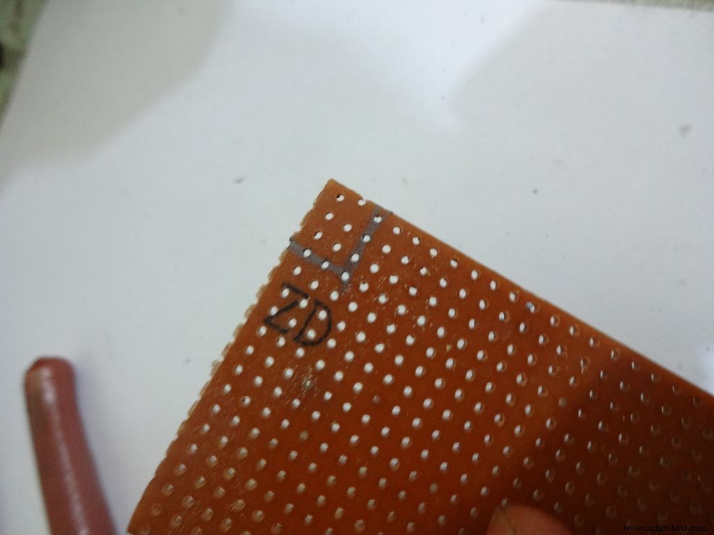
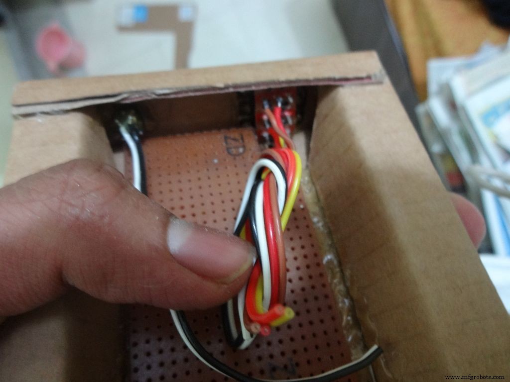
Cut the General purpose PCB to the right size such that it fits properly in the case. Mine is 2x4inches. To cut it, use the ruler and cutter and swipe it multiple times on both sides and it breaks off easily then.
Place it inside. If the glue from the side flap lifts the PCB up, reheat the glue to flatten it or lessen the size of PCB a bit.
Cut a small part so that the 3 switches fit in and PCB goes entirely inside.
Step 15:The Circuit Board -- Arduino Nano

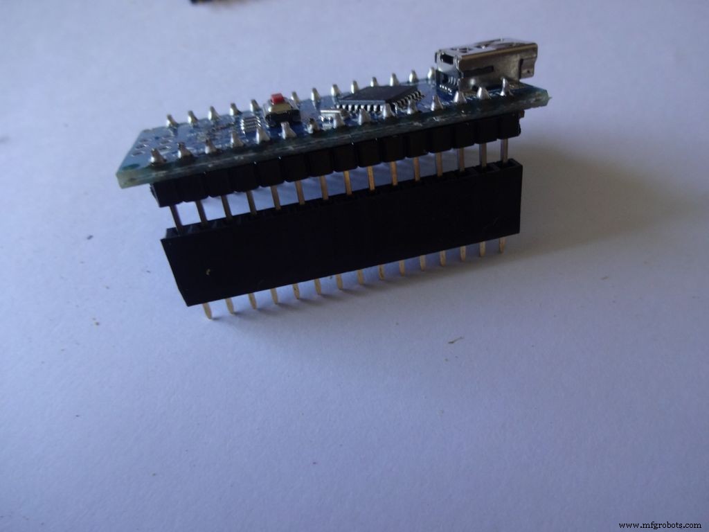

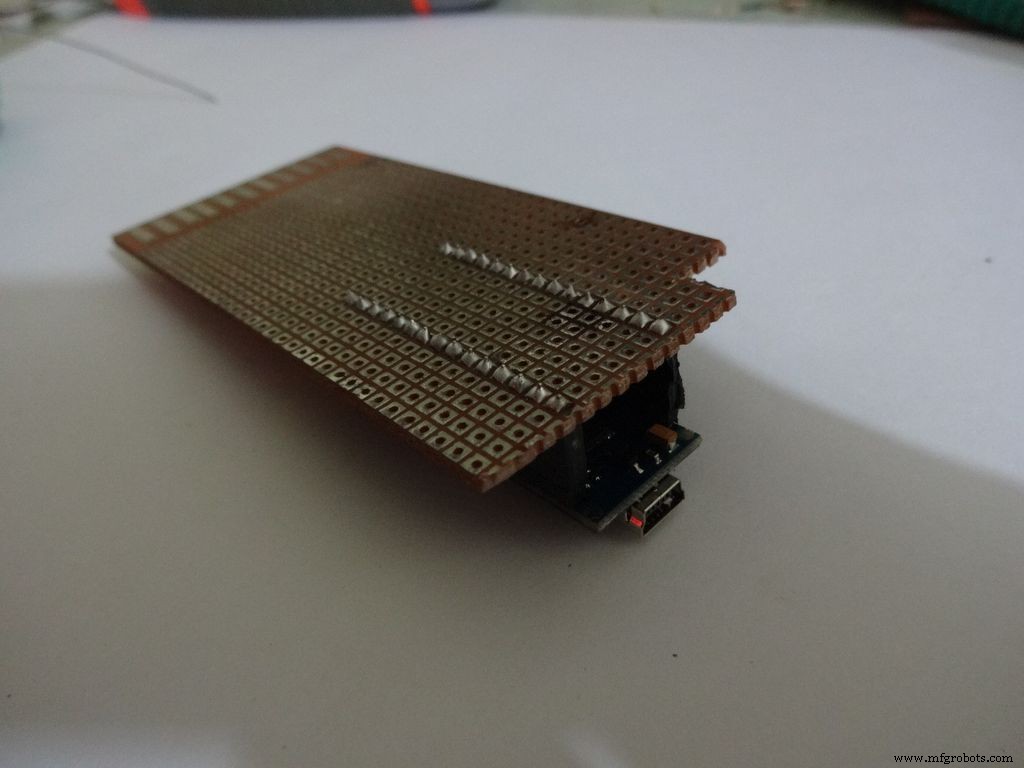
Cut female header pins of the right size for the Arduino.
Place it at the center edge of the PCB and solder all the pins.
Step 16:The Circuit Board -- Ohmmeter
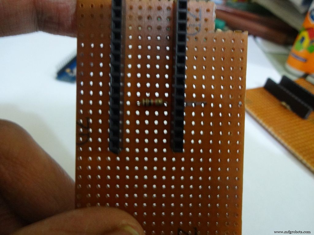
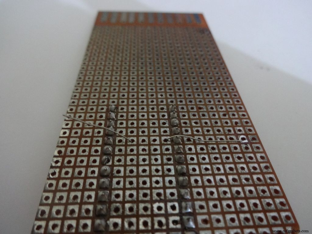
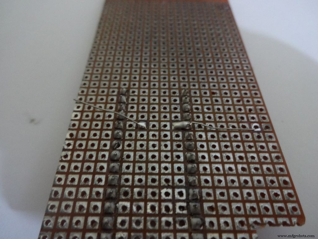
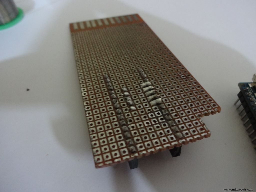
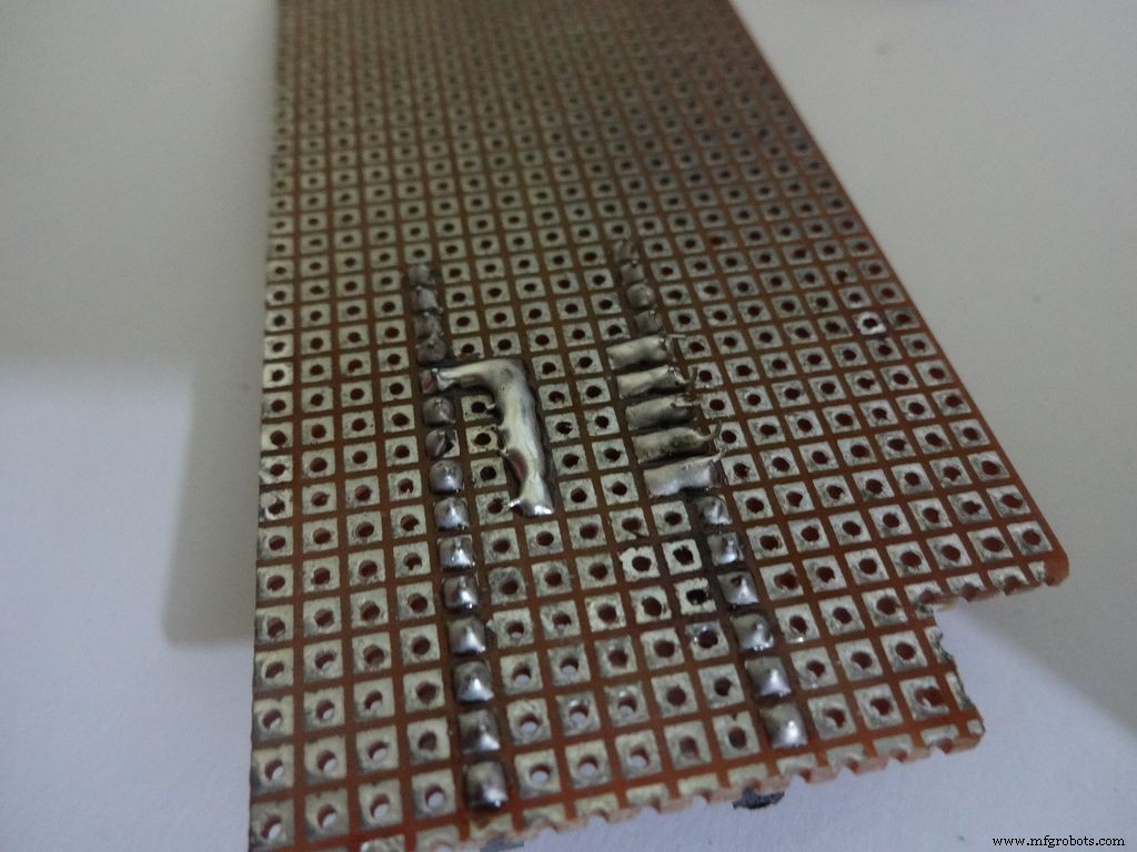
Before making any connections on the PCB please double check from the final Circuit Design.
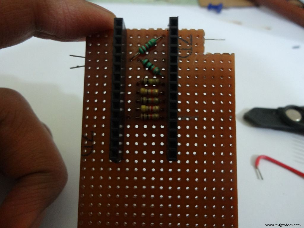
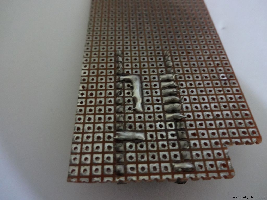
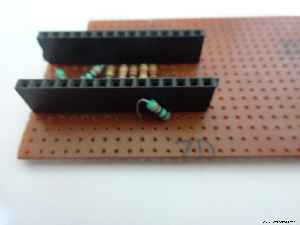
For the ohmmeter start by adding a 1k Ohm resistor to pin D2 of arduino. Place the arduino and carefully mark the pin. On the reverse side, bend as shown and solder it.
Do the same with the other 4 resistors, 4.7k, 10k, 47k and 100k Ohm.
Note:keeping all the tolerance bands(gold band) on one side is a good practice, eg UP and RIGHT.
Combine the second ends of resistors and solder it to A7 .
Step 17:The Circuit Board -- Capacitance Meter and Diode Test
Capacitance Meter:
Solder a 220 Ohm resistor from D12 to A0 . And a 10k Ohm resistor from A0 to D7 .
Note: D7 (digital pin) is also used for LCD data pin D4 .
Diode Test:
Solder the 10k Ohm pullup resistor from A6 to +5V .
Step 18:Making connectors for LCD
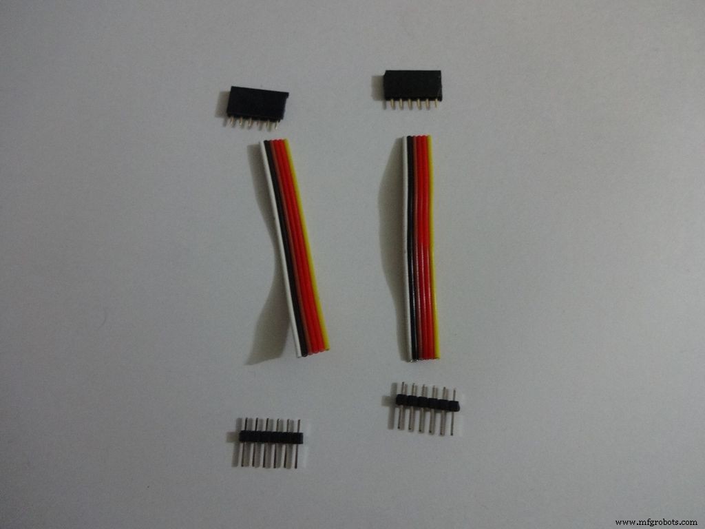
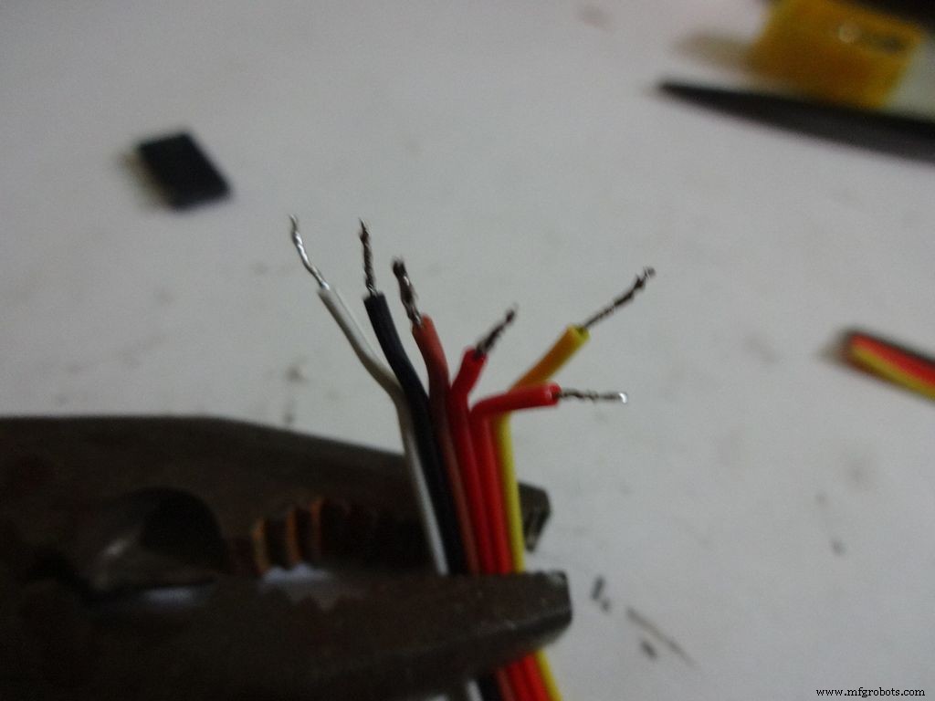
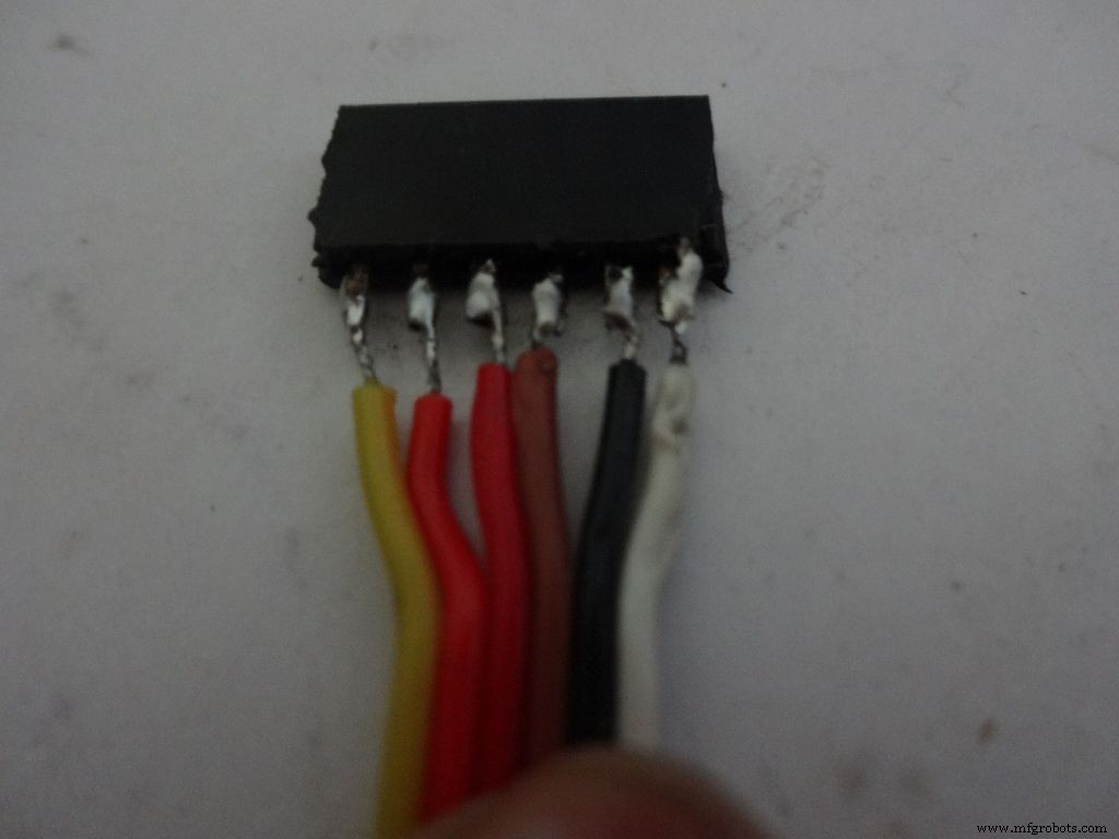
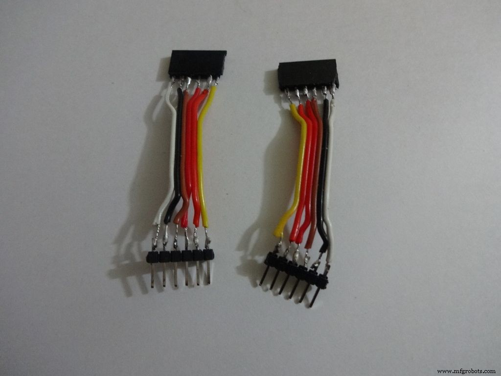
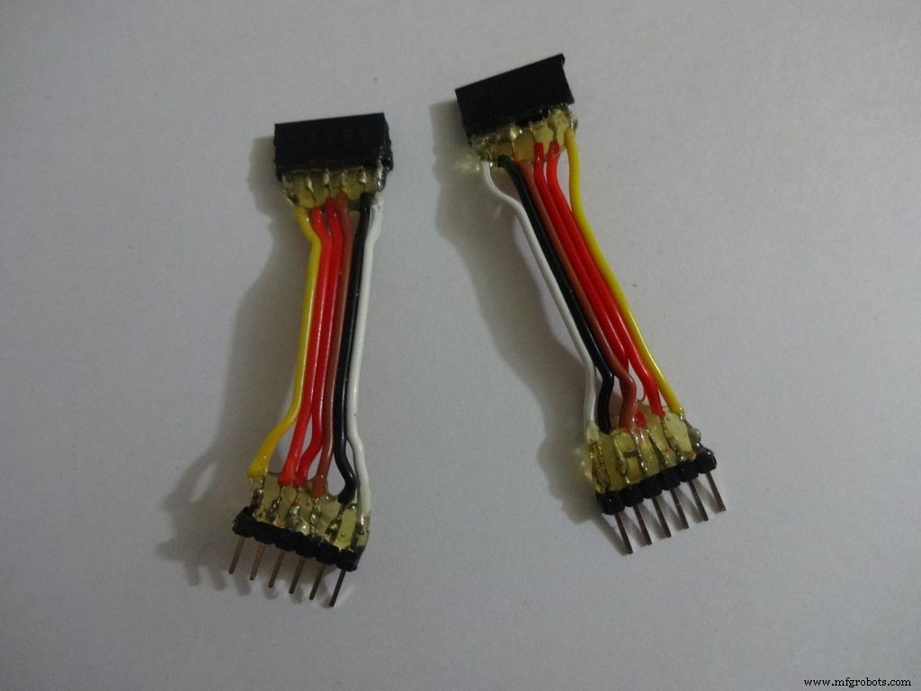
We just use the first 6 and last 6 pins on the LCD. Pins D0-D3 are unused. So we will be making connectors for only the used pins. It is recommended that you do the same because plugging/unplugging a 16pin connector becomes very tough once the build is complete.
Cut 2x 6pin female and male header pins. Also take 6 wire ribbon cable, around 2-2.5 inches long.
Strip the insulation and tin the leads. Also tin the header pins. Join them one by one just like the slide switches.
Apply hot glue to secure the wires.
Step 19:The Circuit Board -- LCD connections
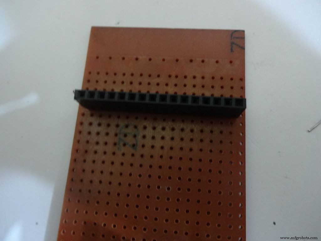
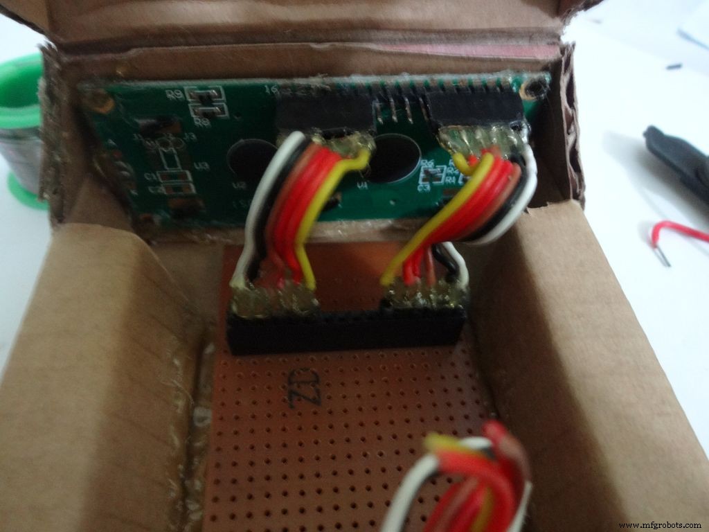
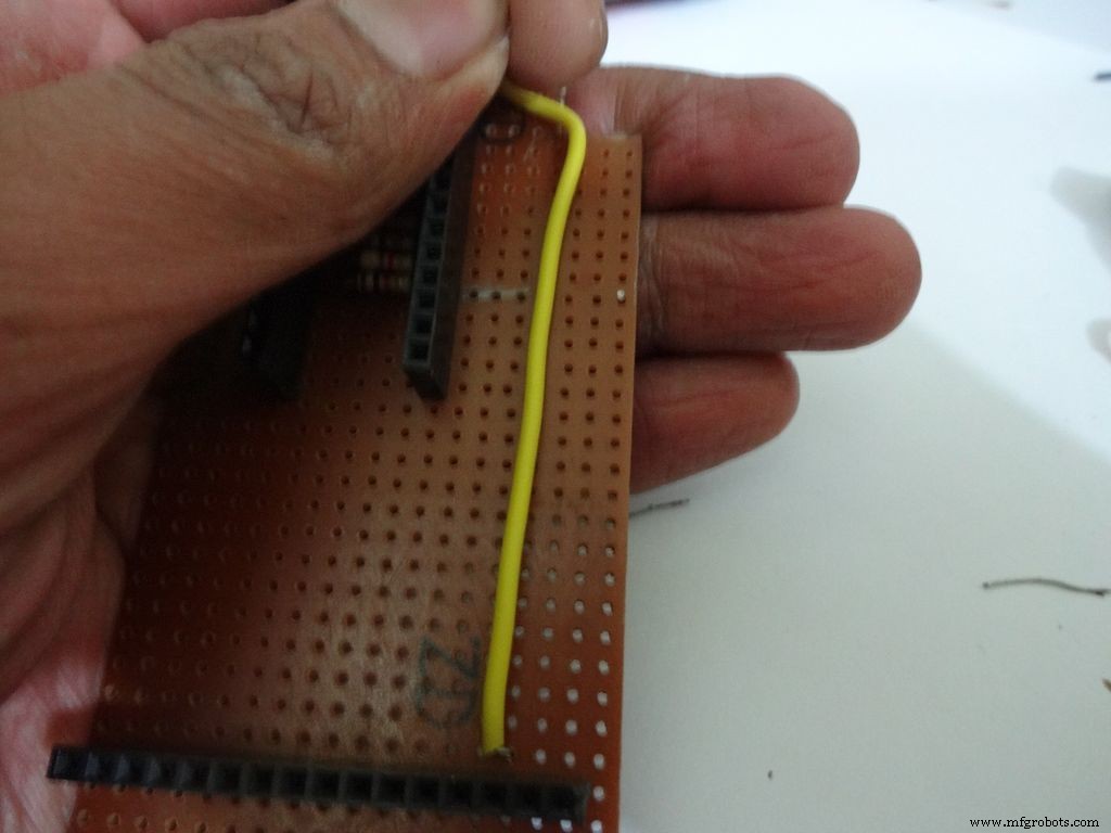
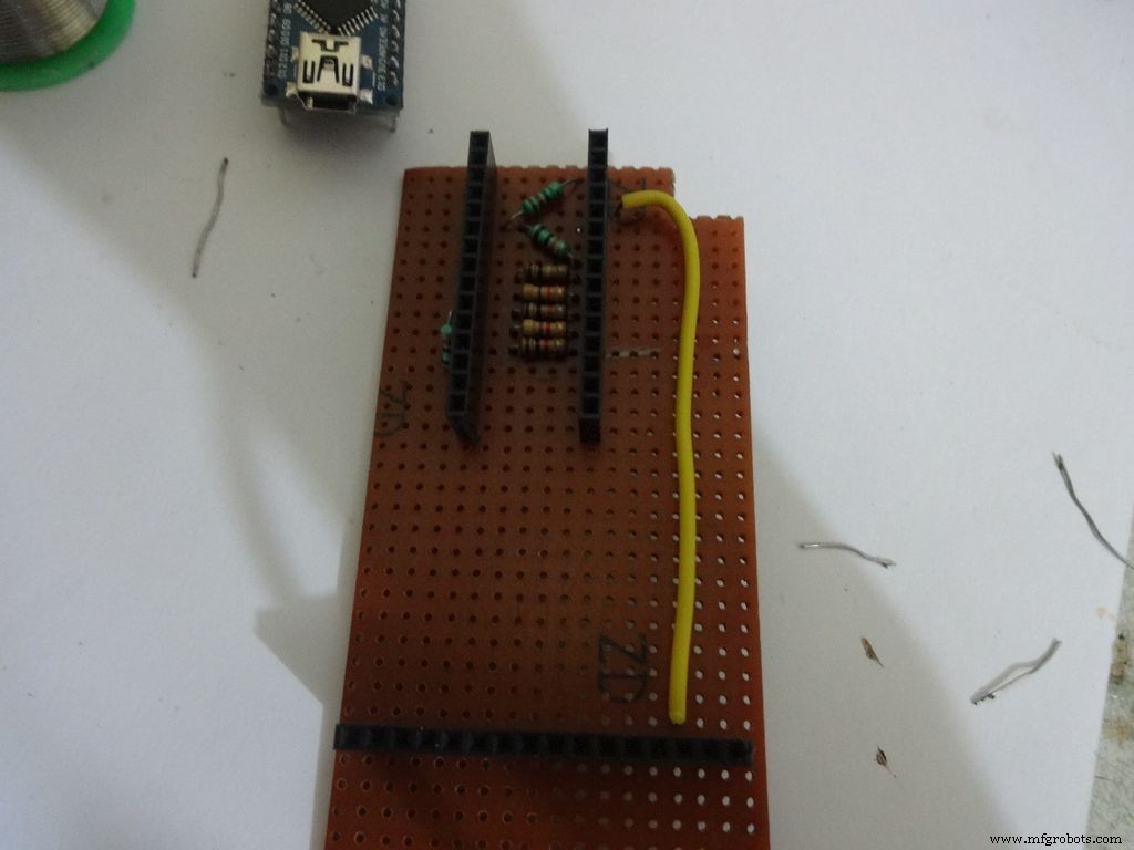
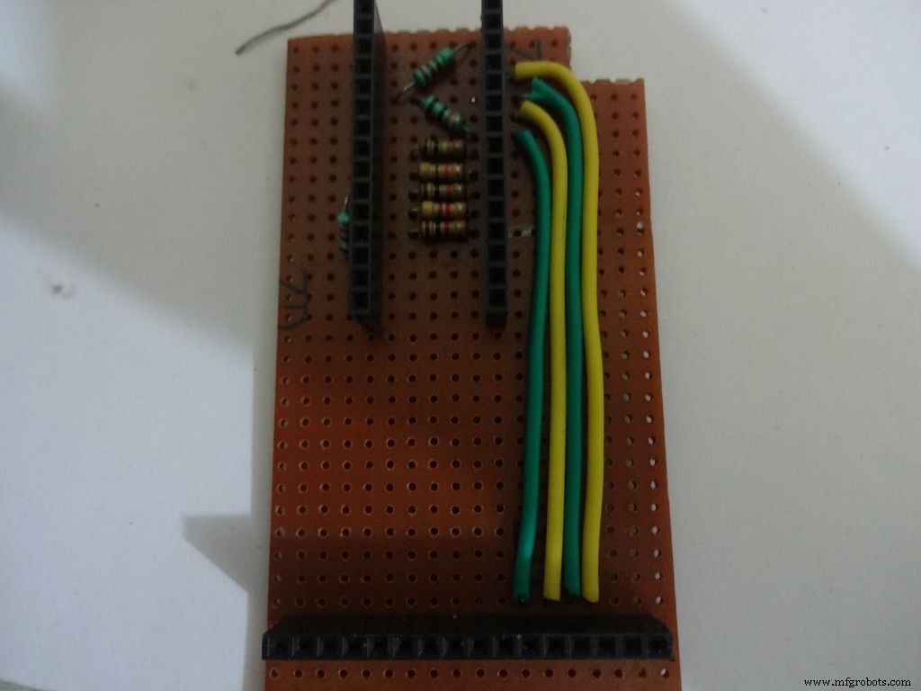
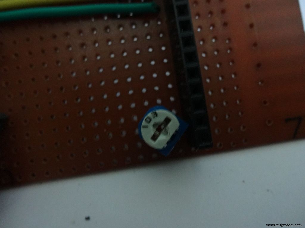
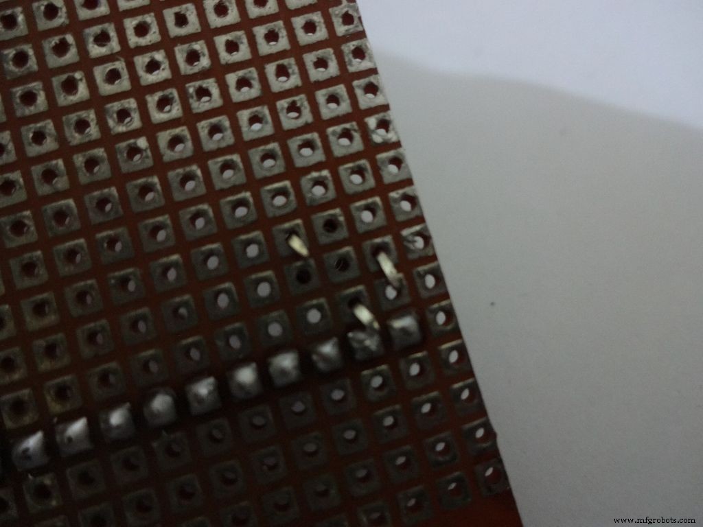
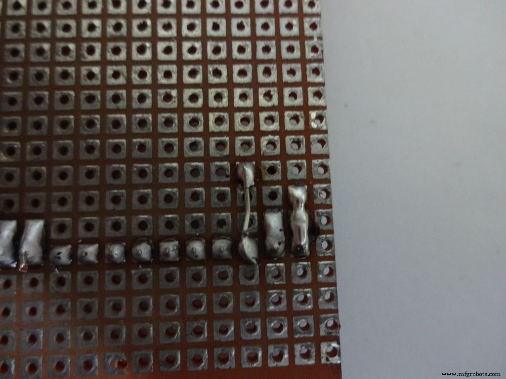

Place the PCB inside the case. Plug the connector to LCD and see where the female port should be on the PCB, solder it.
Make sure you leave 4-5 dot rows behind the LCD port. The Power switch will be added here later.
Measure the length of single stranded wire needed to connect data pins (D4 , D5 , D6 and D7 ) on the LCD to digital pins( D7 , D8 , D9 and D10 ) on the Arduino, respectively.
Add the 10k ohm potentiometer such that the side ends go to Vcc , GND and the middle pin to V0 .
Connect Vss(GND) on the LCD to GND , and Vdd to +5V . Also connect R/W to GND .
Arduino Pin
LCD
D7 D4 D8 D5 D9 D6 D10 D7 GND Vss(GND) +5V Vdd
Step 20:The Circuit Board -- RTC Module
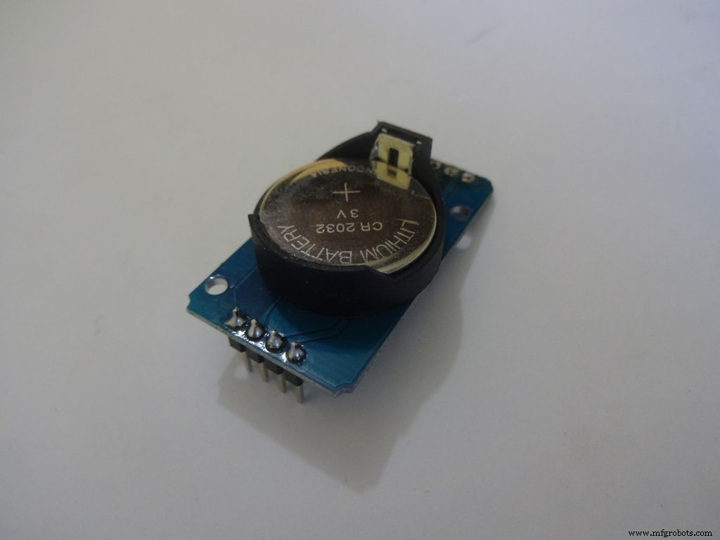
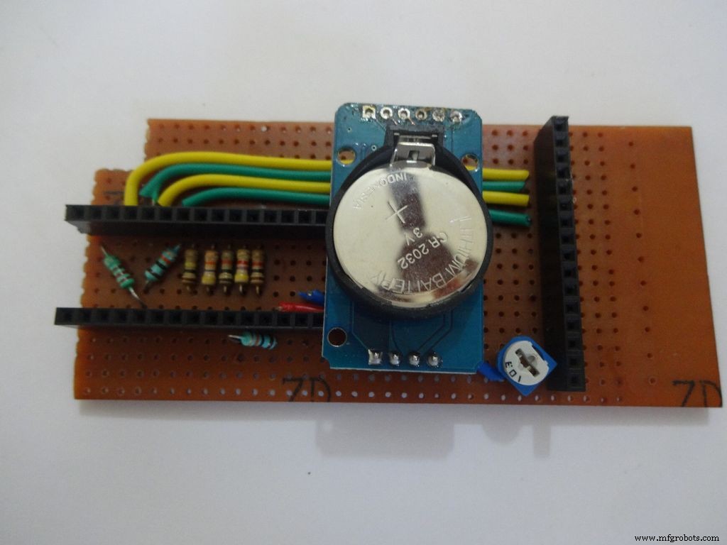
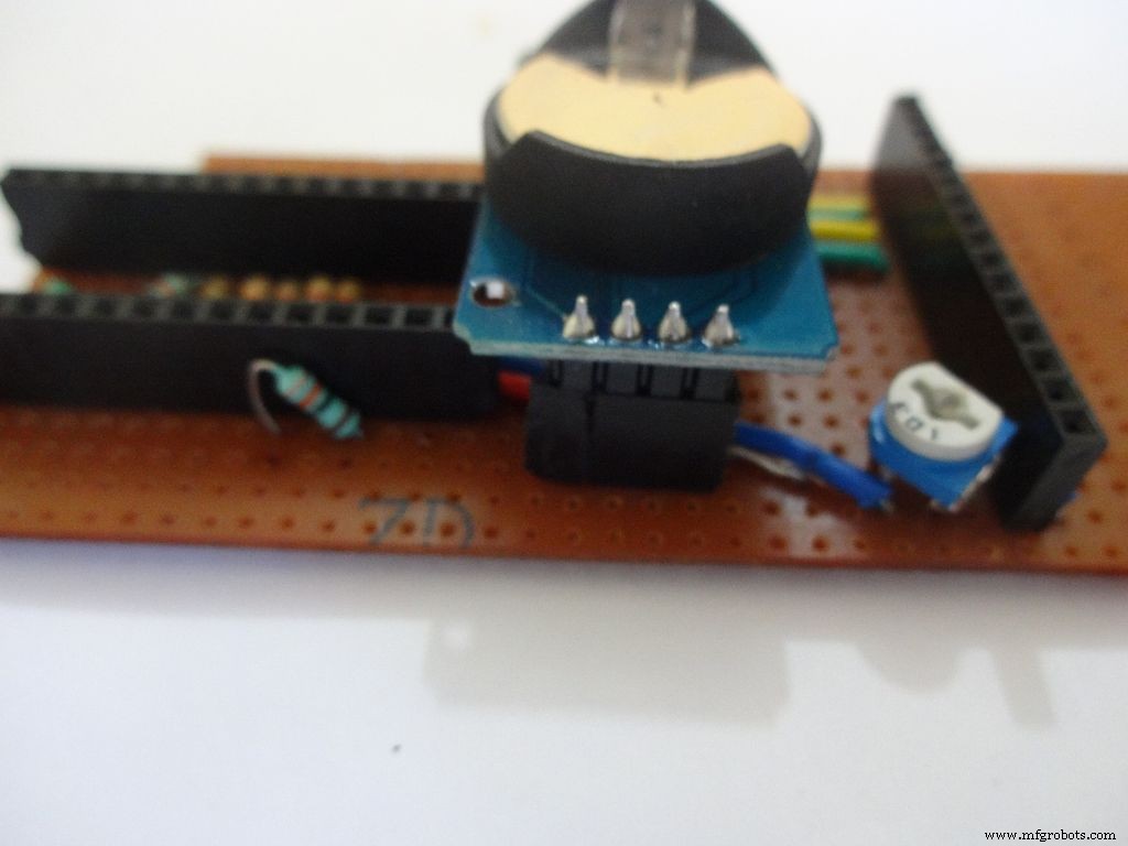
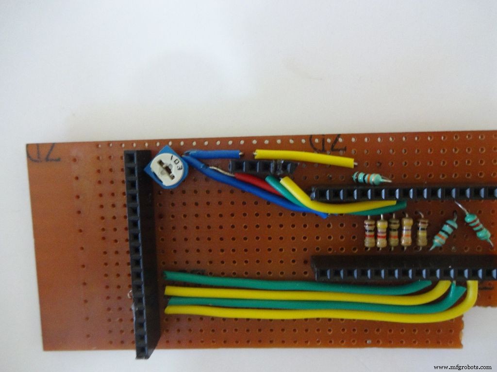
I desoldered the default 90 degree header pins on the module and added straight ones so that it fits flat on the PCB.
Solder 4pin female header pin and make connections to Vcc , GND , SDA to A4 and SCL to A5 .
Step 21:Making the Case -- The mode button
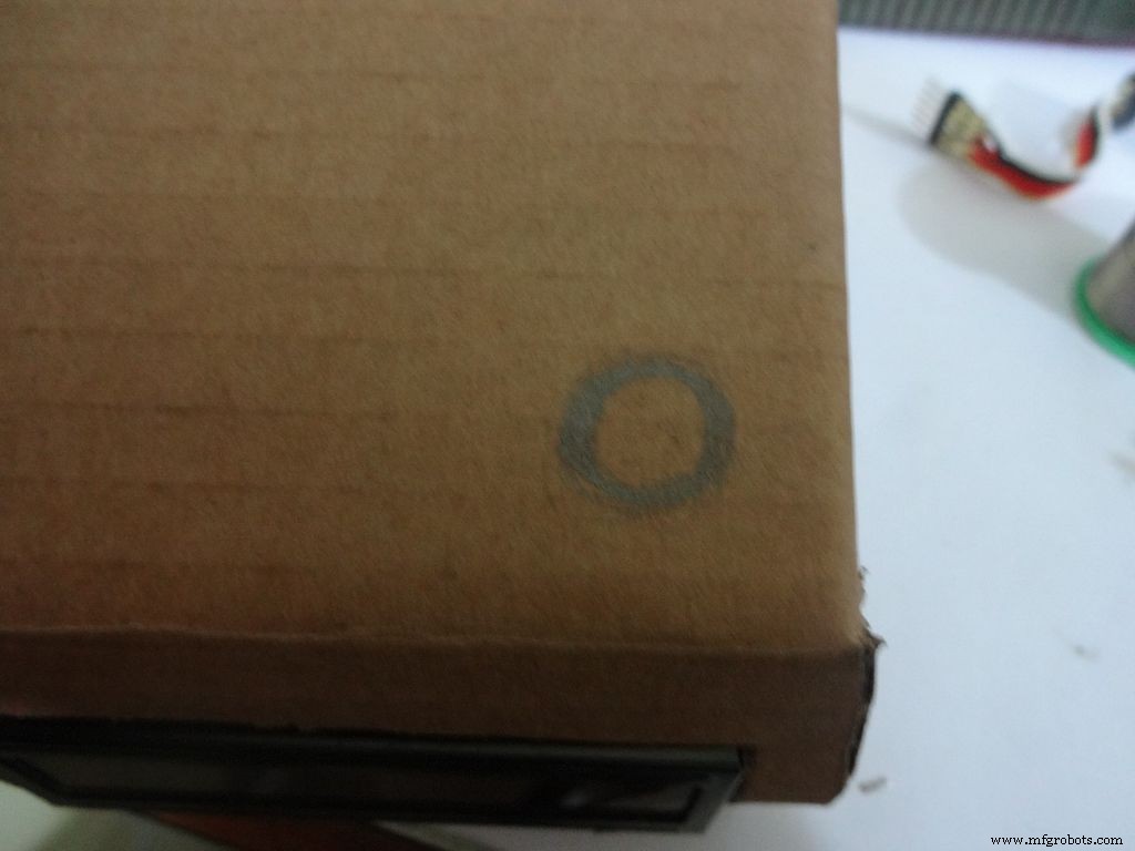
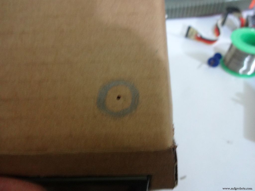
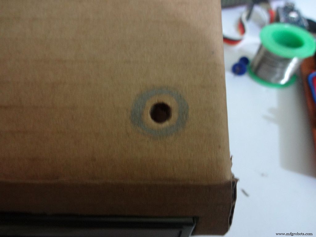
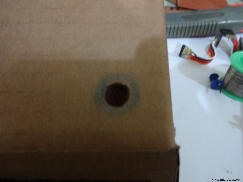
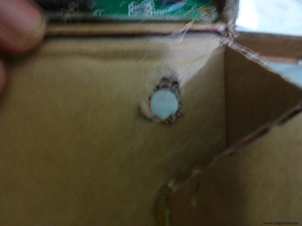
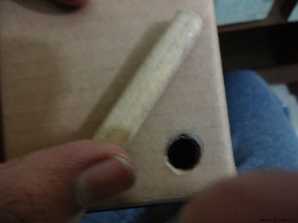
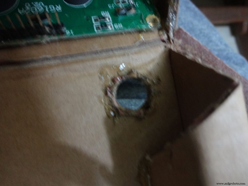
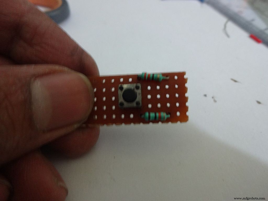
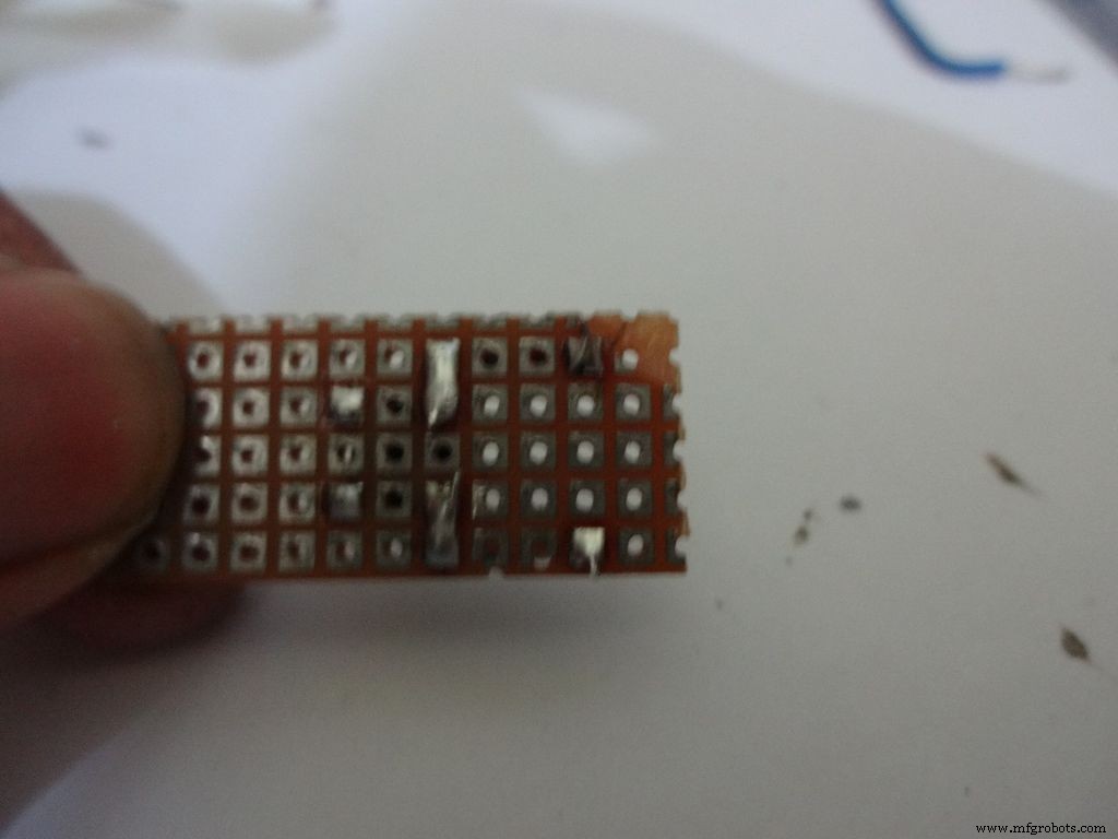

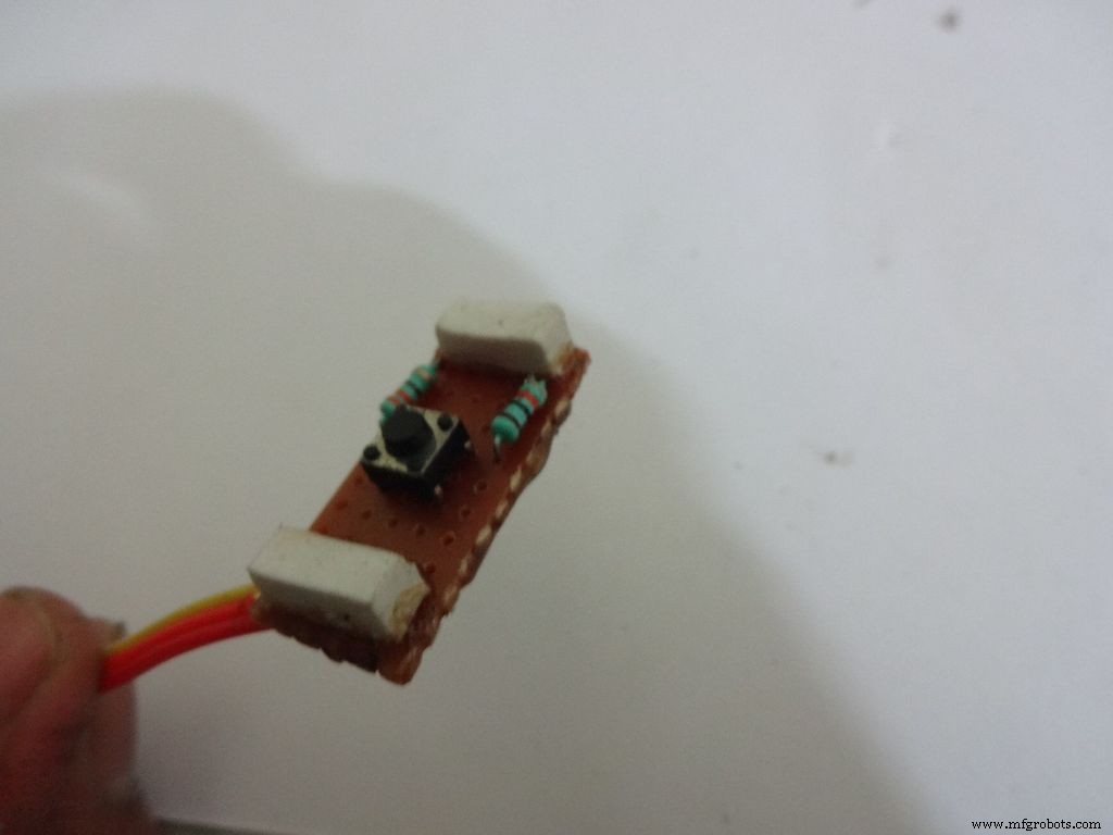
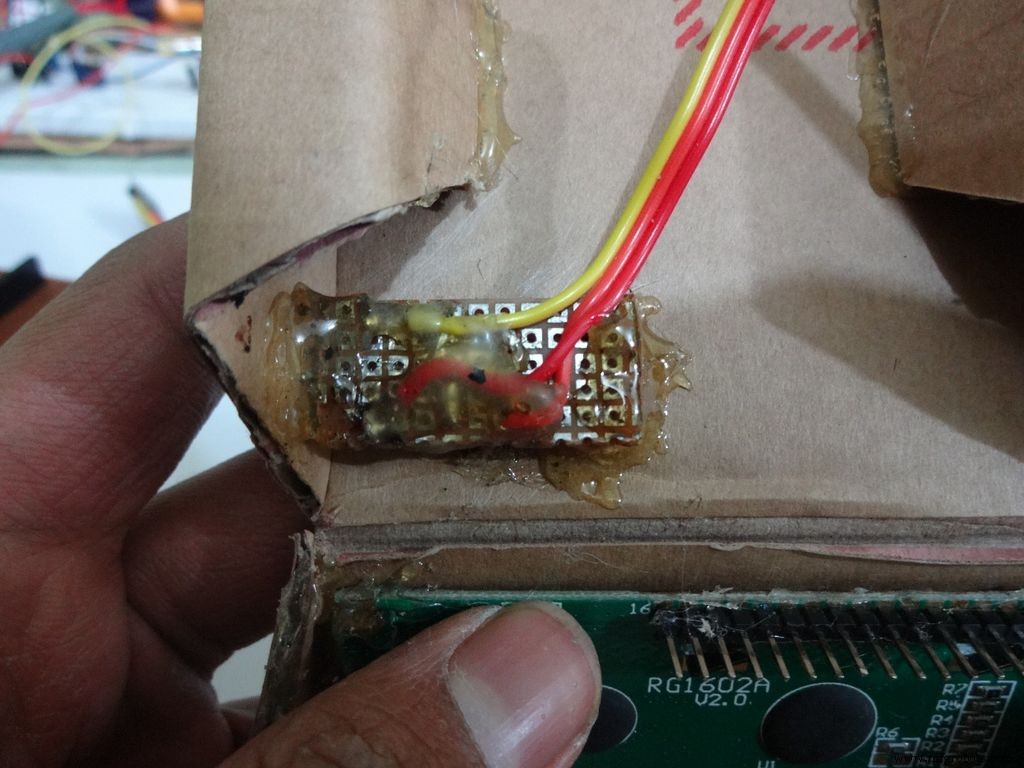

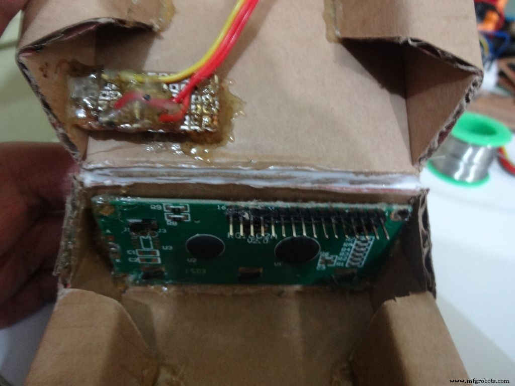
Mark a circle of about 1cm diameter at the pin1 corner of the IC case. mark the center with a pin, use a pencil to expand it. After that use some appropriate tool to increase the diameter to 1cm. Sand it on the inside and use hot glue to secure the hole.
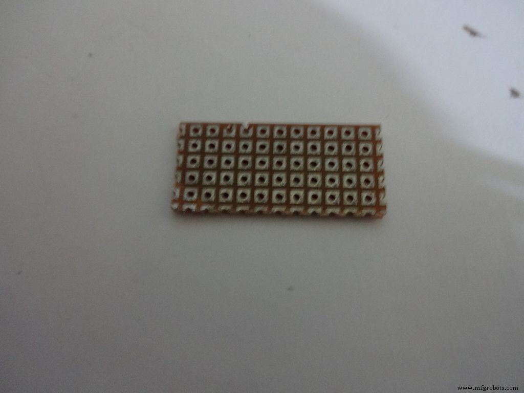
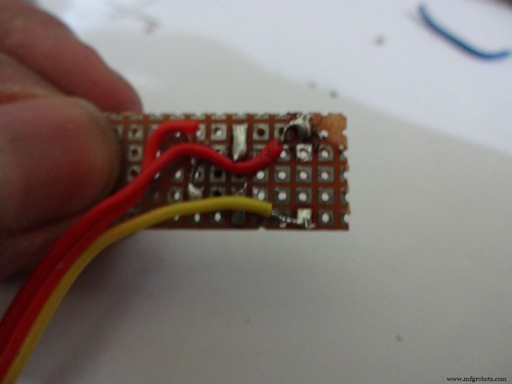
Cut a piece of General purpose PCB (10-11)dots x 5dots. Plug in and solder the pushbutton, 220 and 10k Ohm resistors as shown.
Take 3wire ribbon cable about 15cm long. Tin the ends and solder it as shown. Note down which colour wire goes to where, this will be helpful later on.
Cut 2 small pieces of eraser and place it on the ends on the board. The height of the eraser should be such that the button is below the cardboard inner level as viewed from outside. I used 4mm.
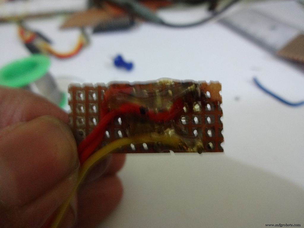
Secure it with hot glue as shown
Step 22:Making the Case -- Testing points
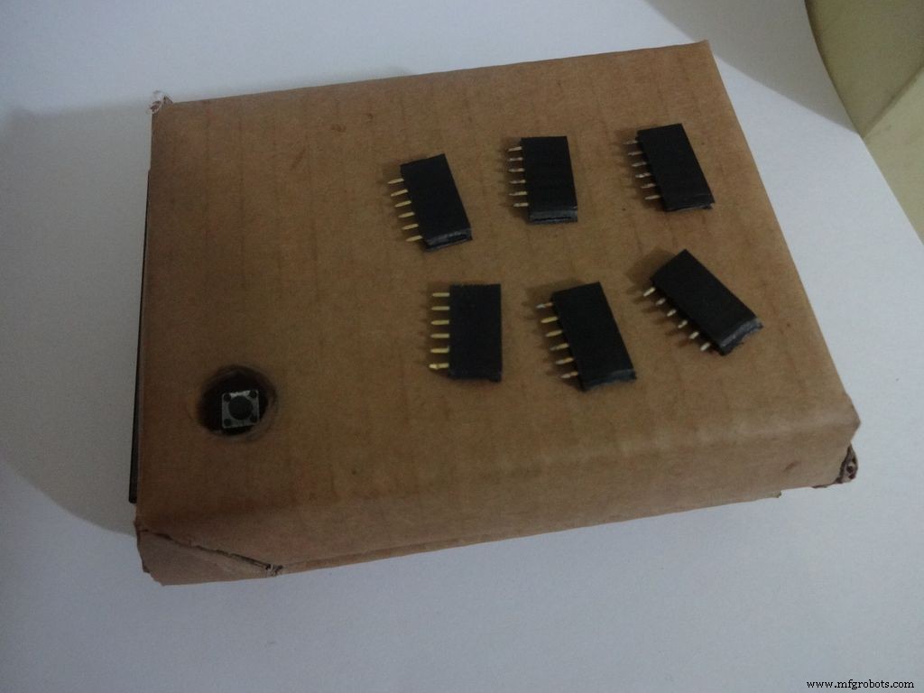
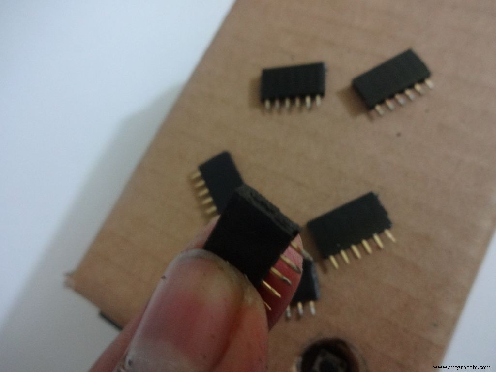
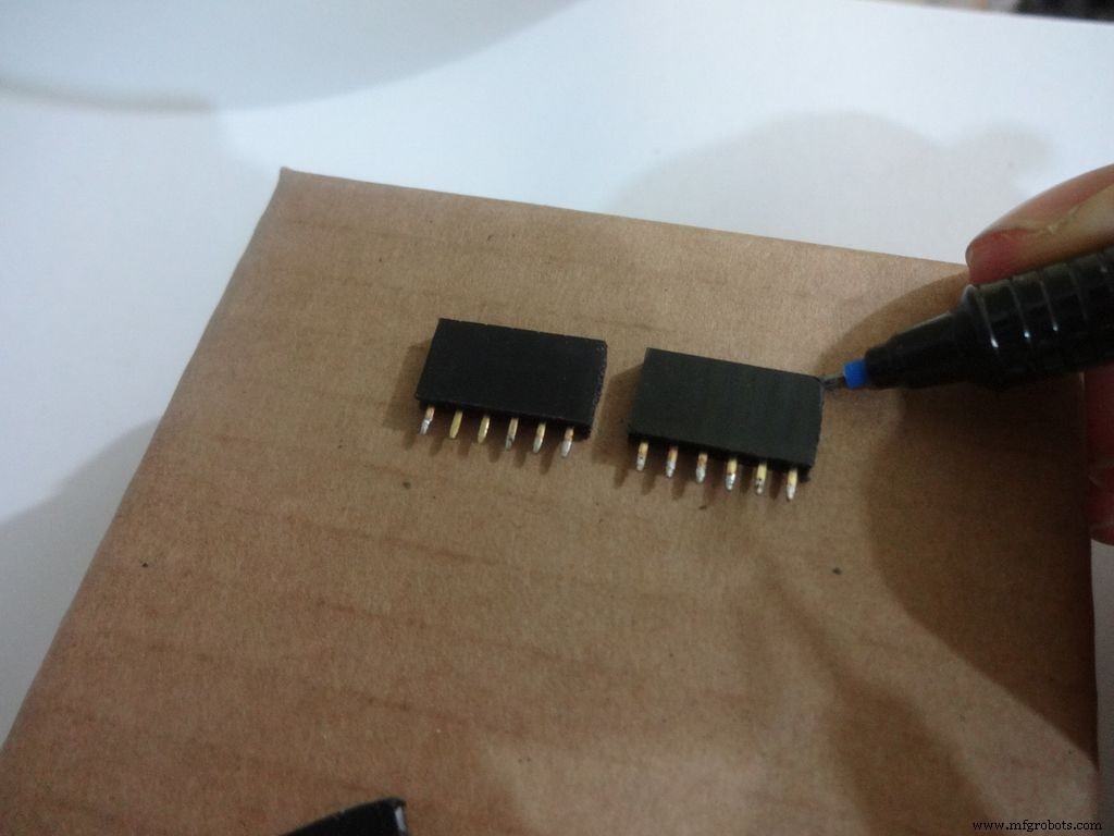
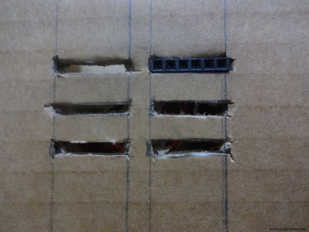
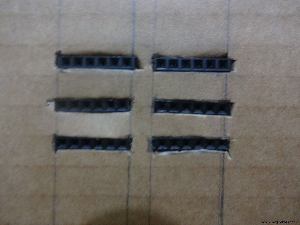
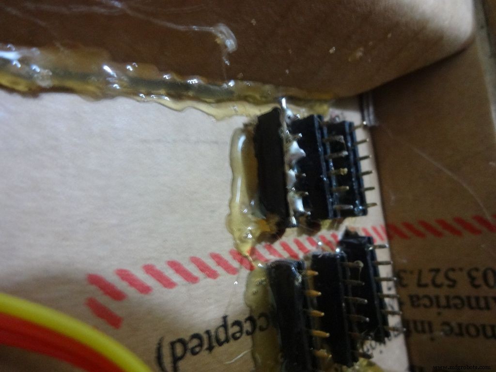
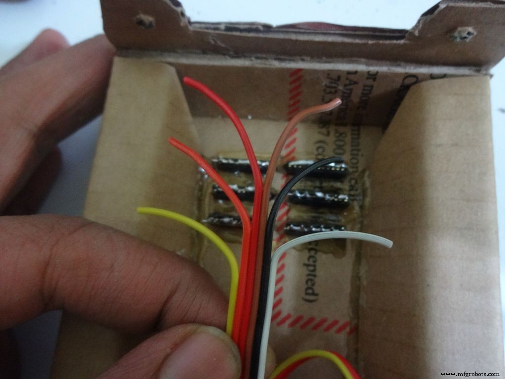

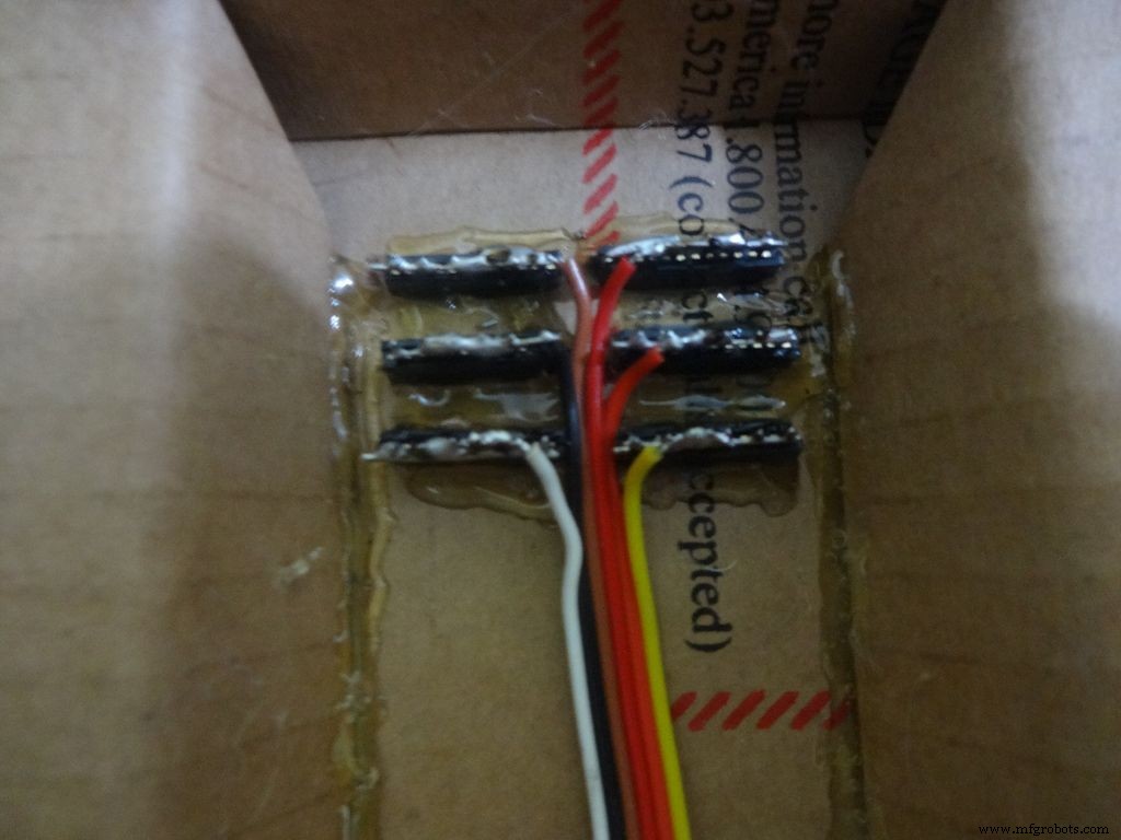
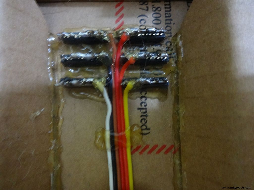
Cut 6x 6pin female header pins. Sand the sides to make it smooth.
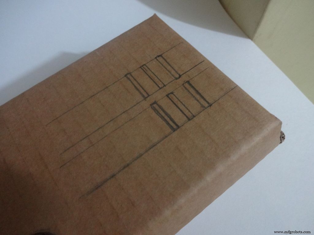
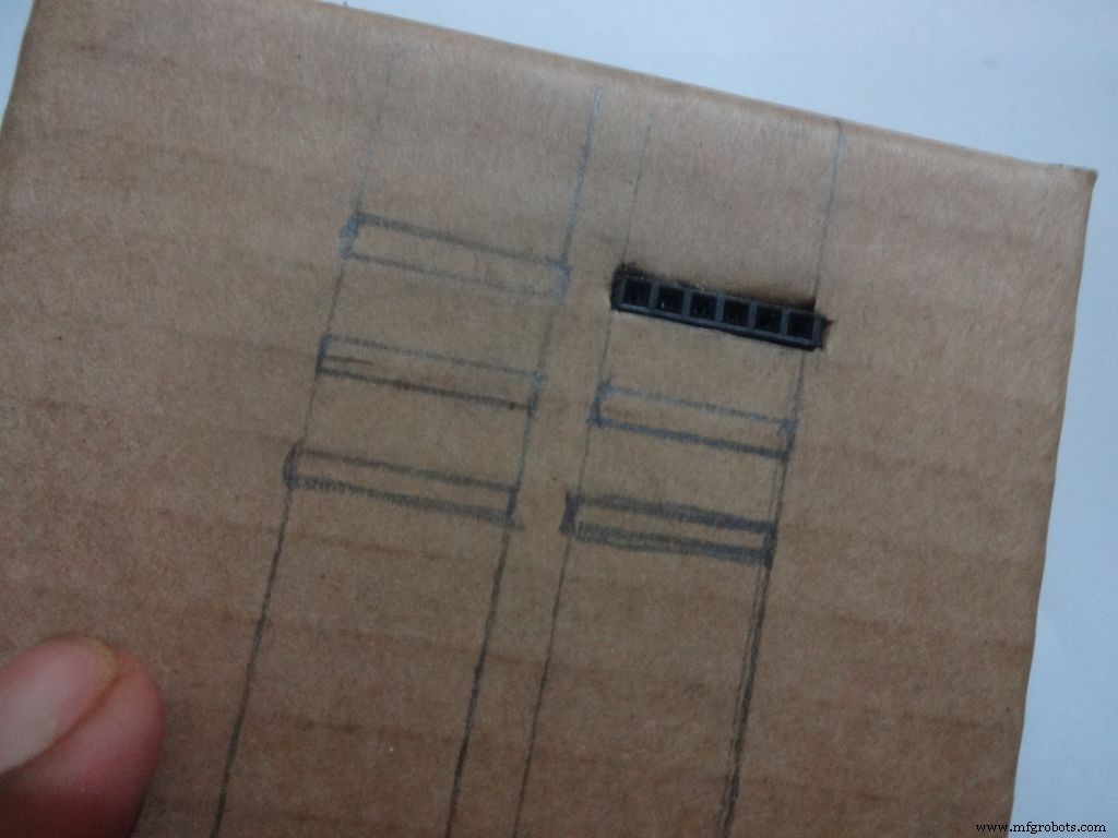
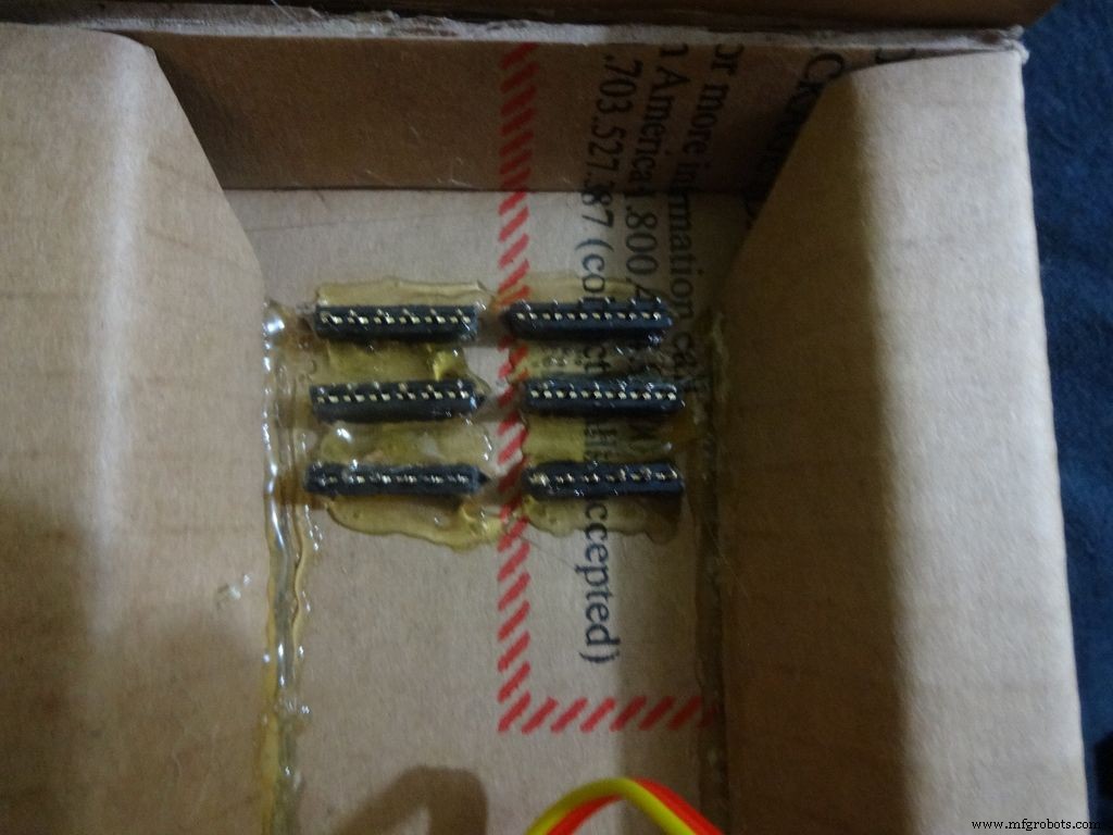
Mark the positions and cut slots for the header pins. Insert it in place and glue it from the inside.
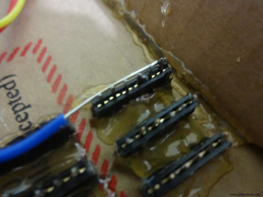
Apply small amounts of solder to all the pins and use a stripped jumper to get it all together. Make sure all of them are connected. Dont keep on heating it to make it perfect. Heating a pin also heats the neighbouring ones.
Take 6 stranded ribbon cable, tin it and attach it to each slot. Note that I put dark colours to the negative side. Apply hot glue to fix them in place.
Step 23:The Legs
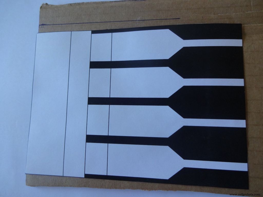

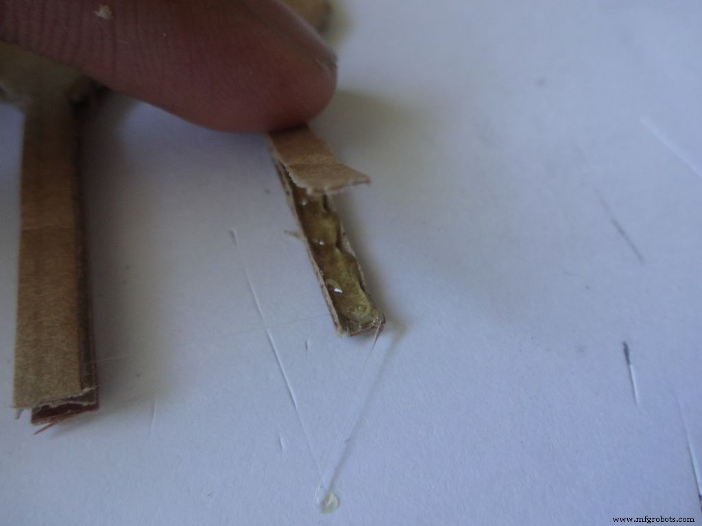
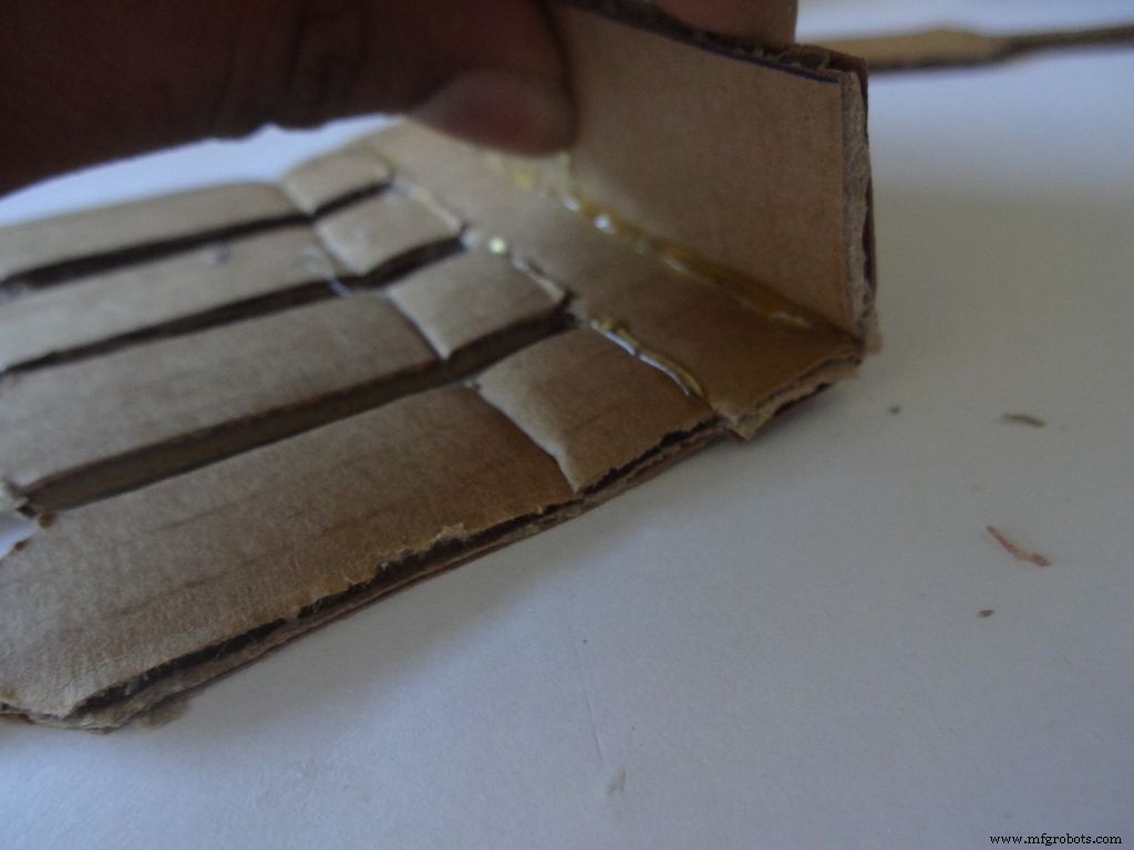
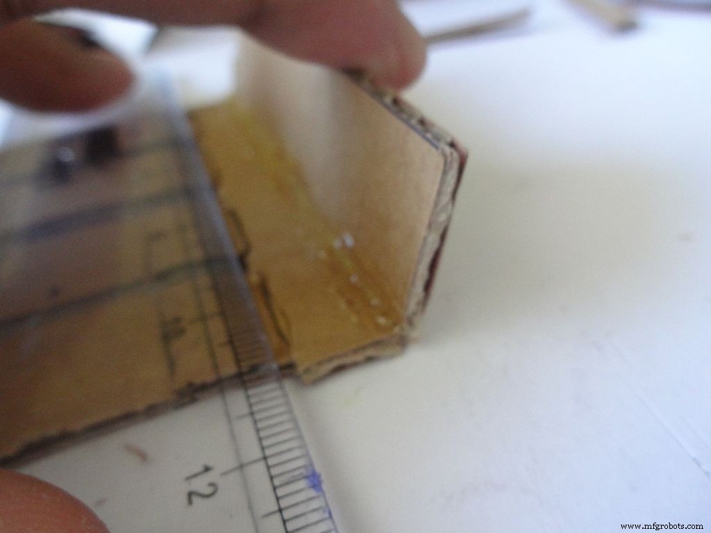
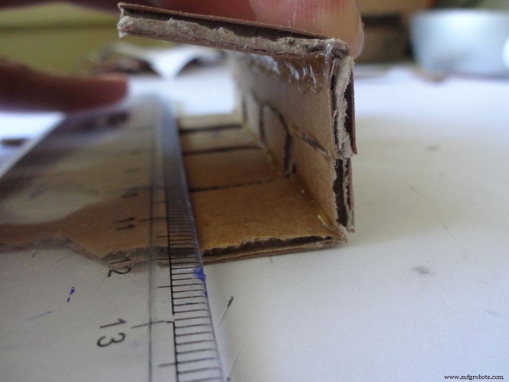

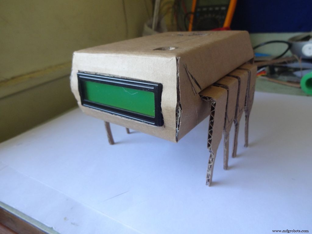
Download "Legs_A4.pdf" or ""Legs_ANSI_A.pdf", based of paper size available in your region. attached at the end.
Print it on an A4 size paper (21 x 29.7cm or 8.27 x 11.69 inches) or the US-alternative ANSI A(8.5 x 11inches or 21.6 × 27.9cm). Make sure that while printing you select the proper paper size, orientation, and select the "Actual Size" option. Confirm that the print is accurate by measuring the rectangle. It should be 8.4 x 11.8cm
Cut crease and glue it just like the main case, see the images.
Step 24:Making it shiny!
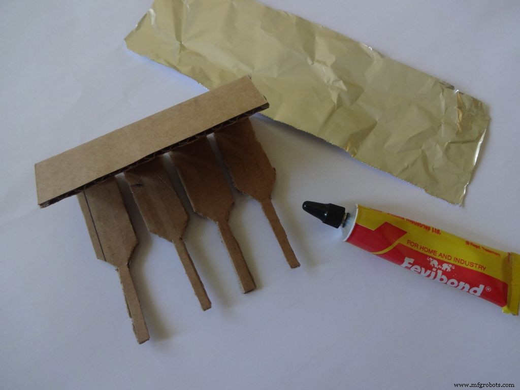
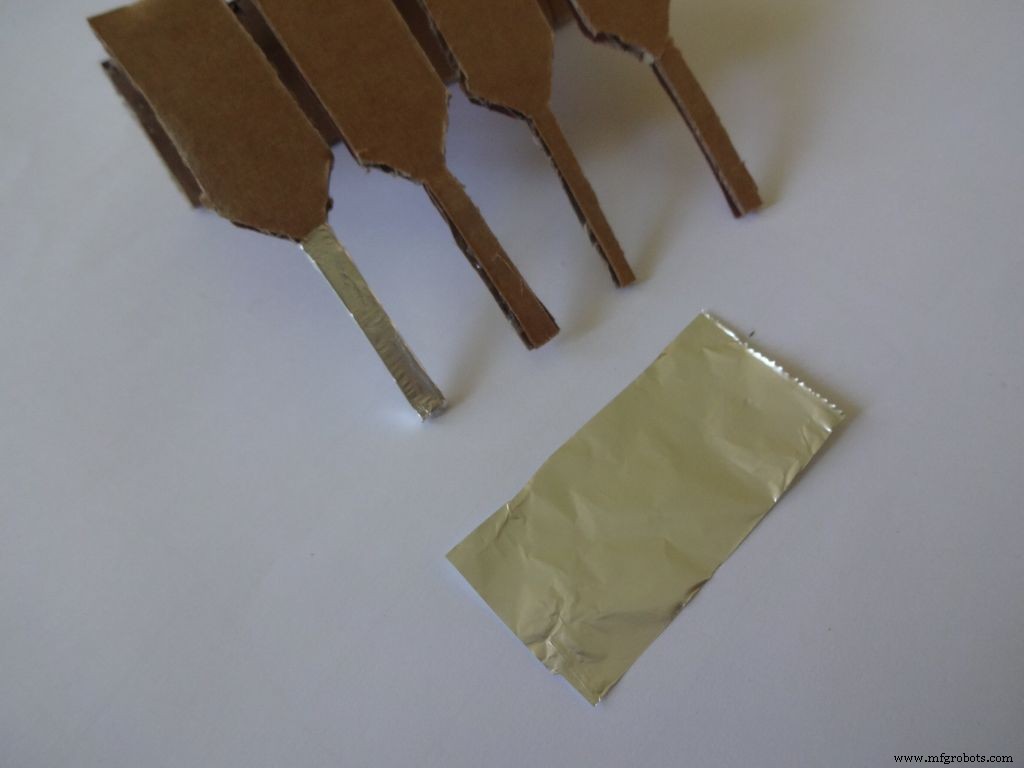
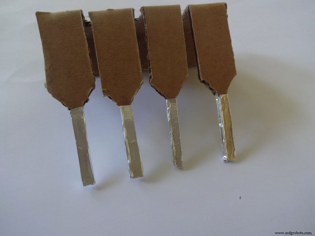
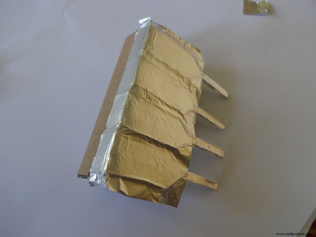
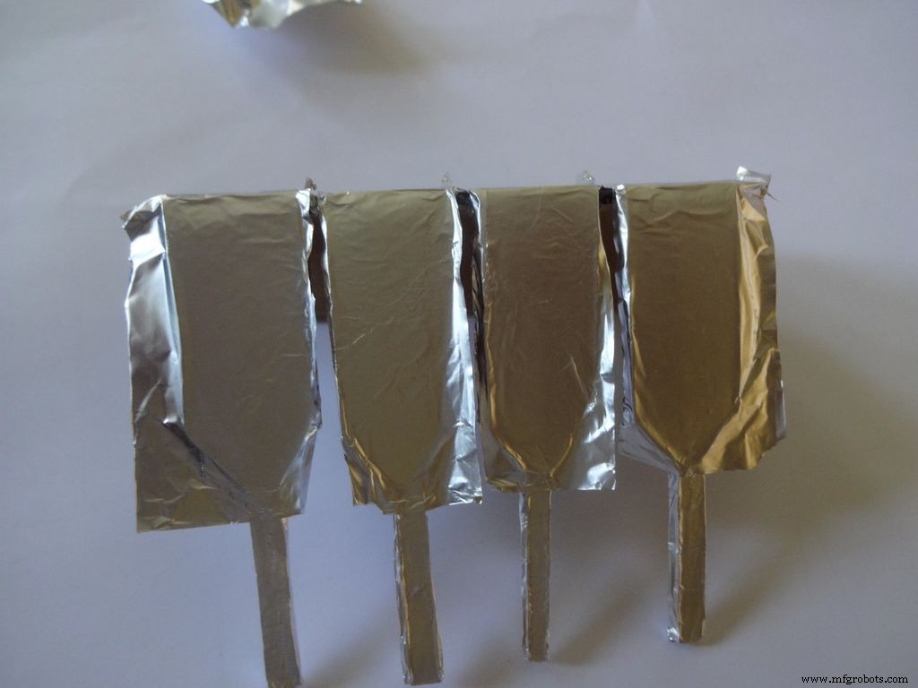
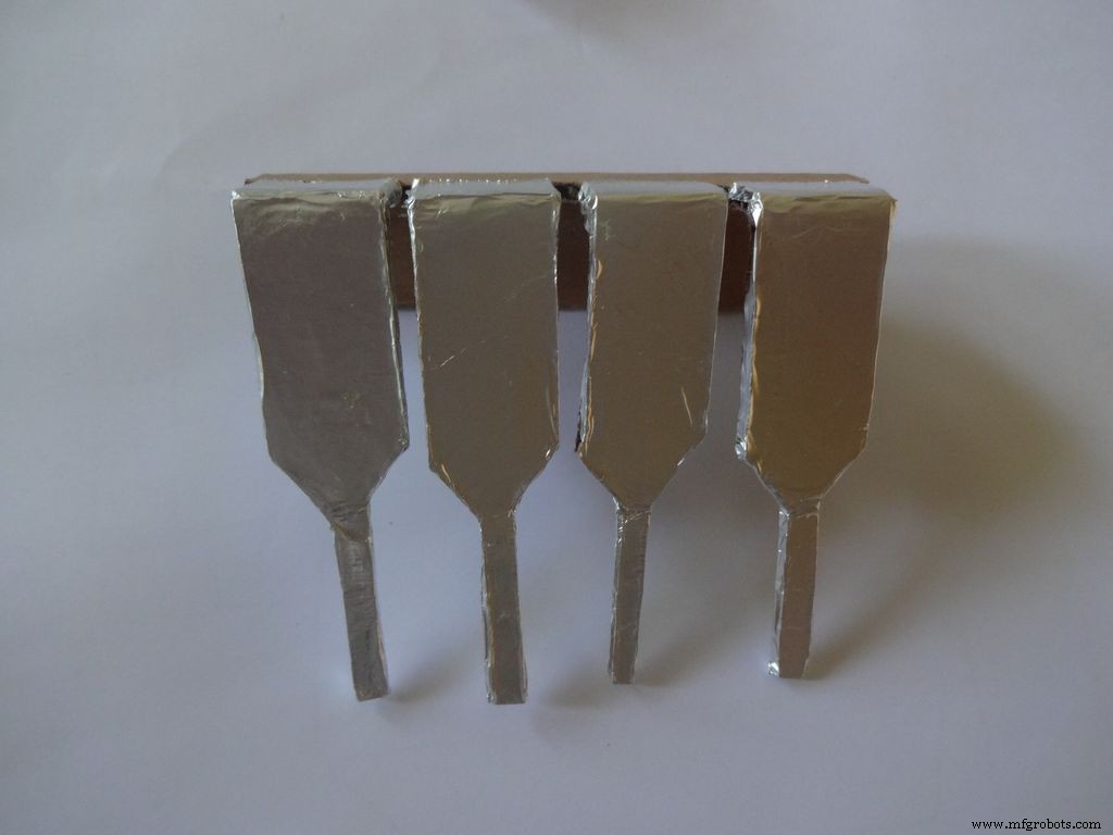
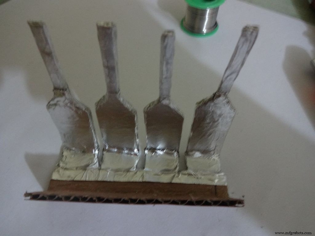
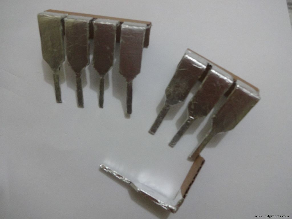
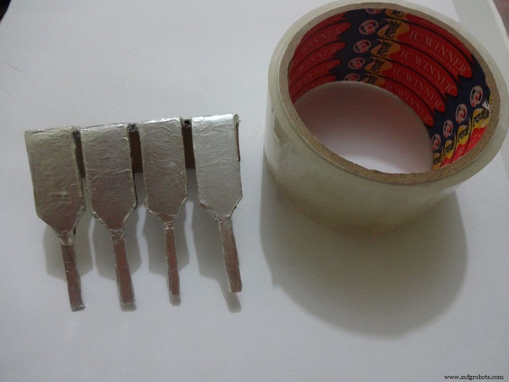

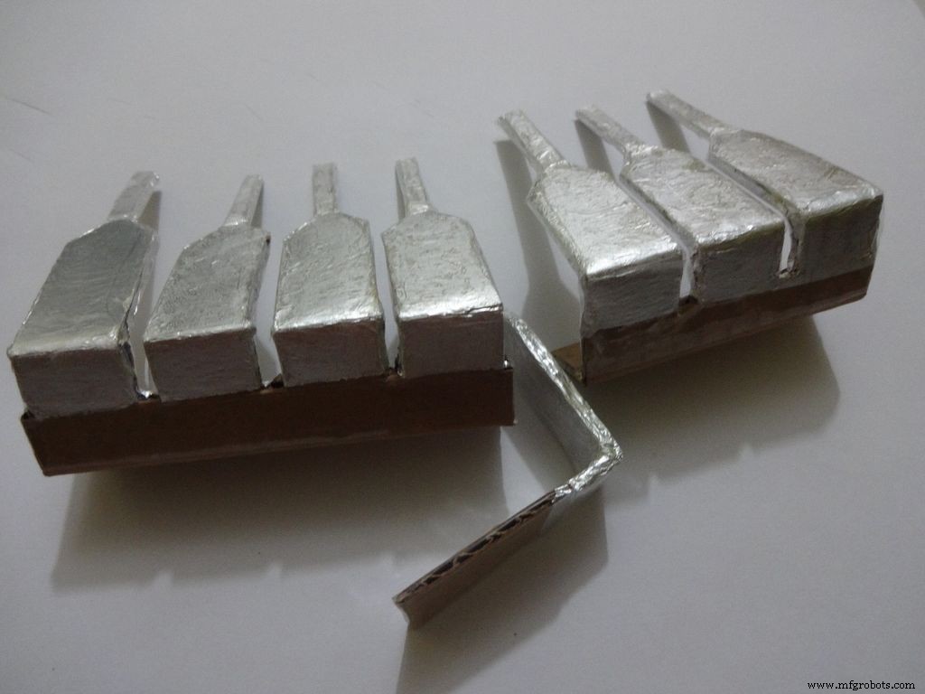
Cut a piece of foil 1x2inches and stick it carefully, fold by fold to the leg ends with some metal-cardboard sticking glue. I used Fevibond.
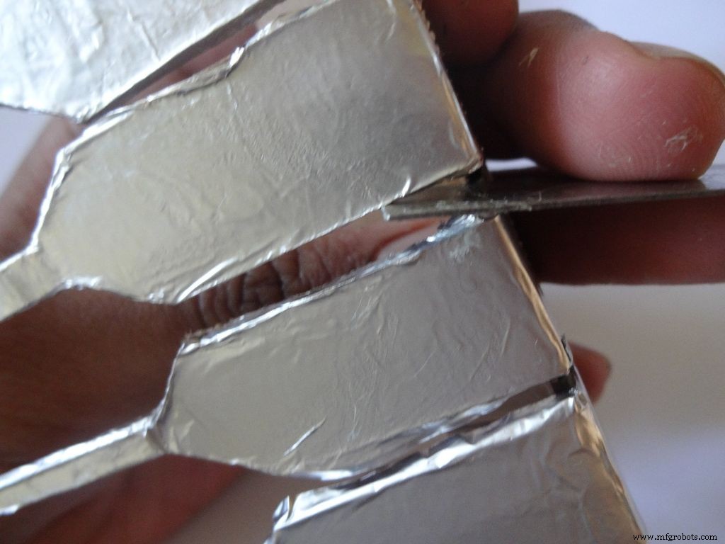
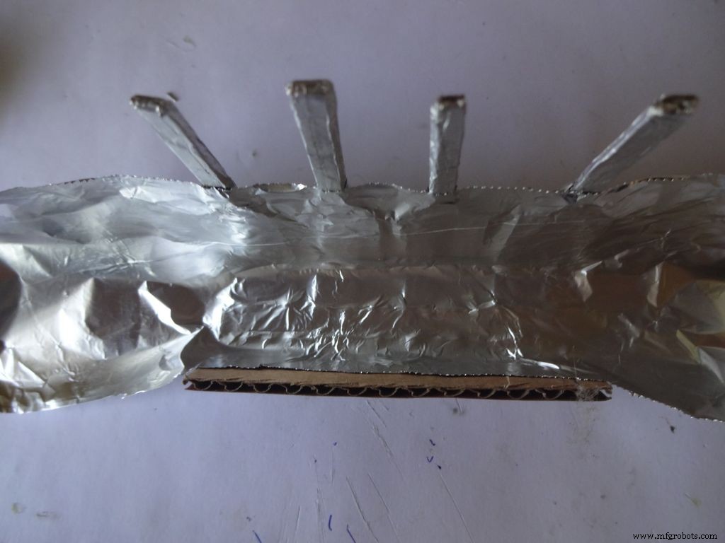
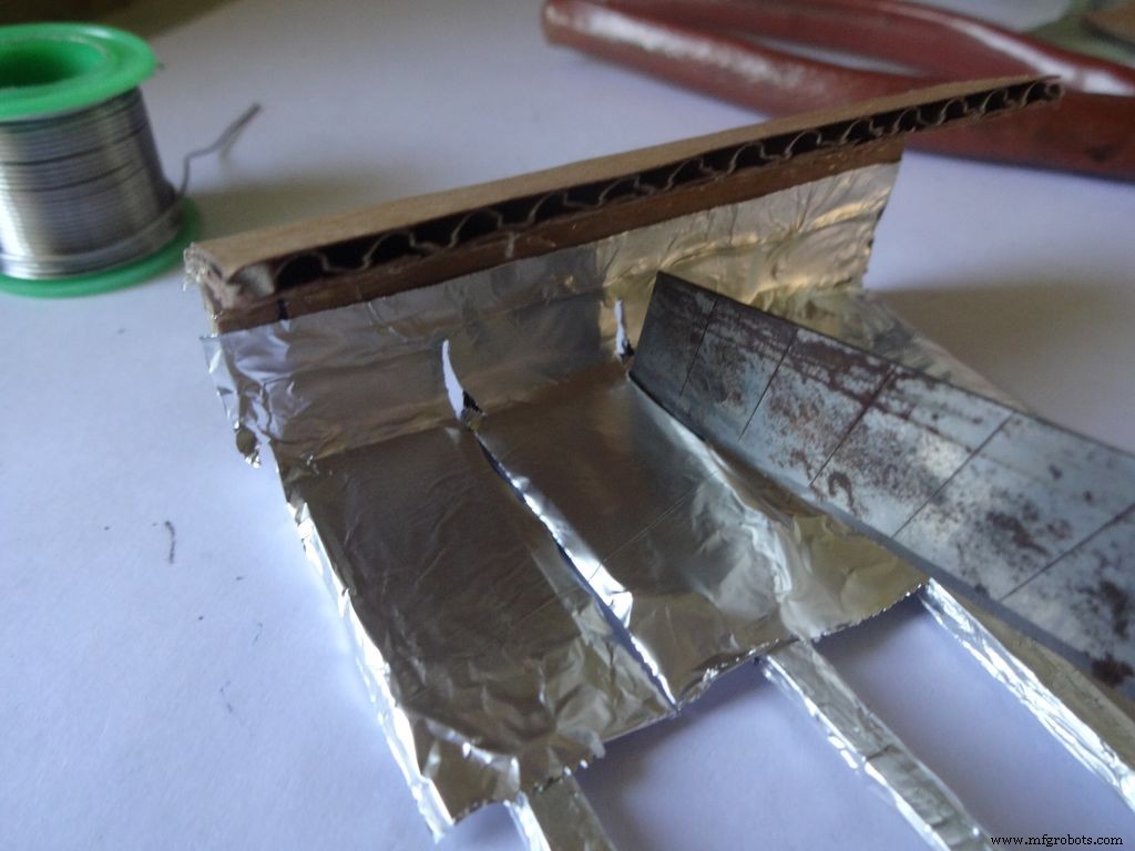
Next stick a patch that covers all the leg tops(as shown), make cuts slowly with a cutter. Do this carefully. The foil tends to tear to the sides. Use something flat to stick the foil in between the legs and give it a good finish.
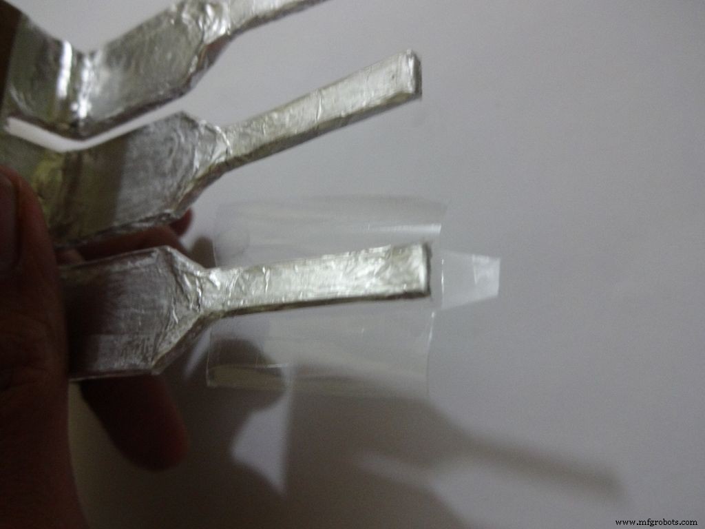
Now cover it with transparent cello tape, just like you applied the foil, to protect it from sharp objects.
Step 25:The Power Switch
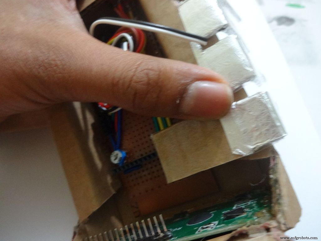
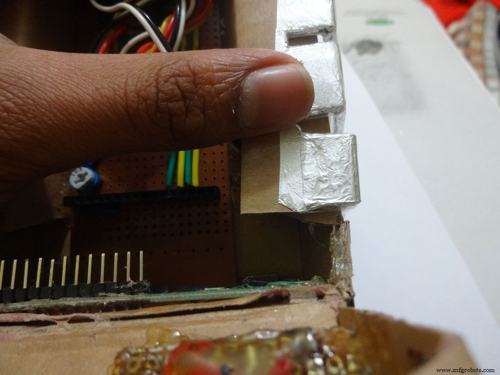
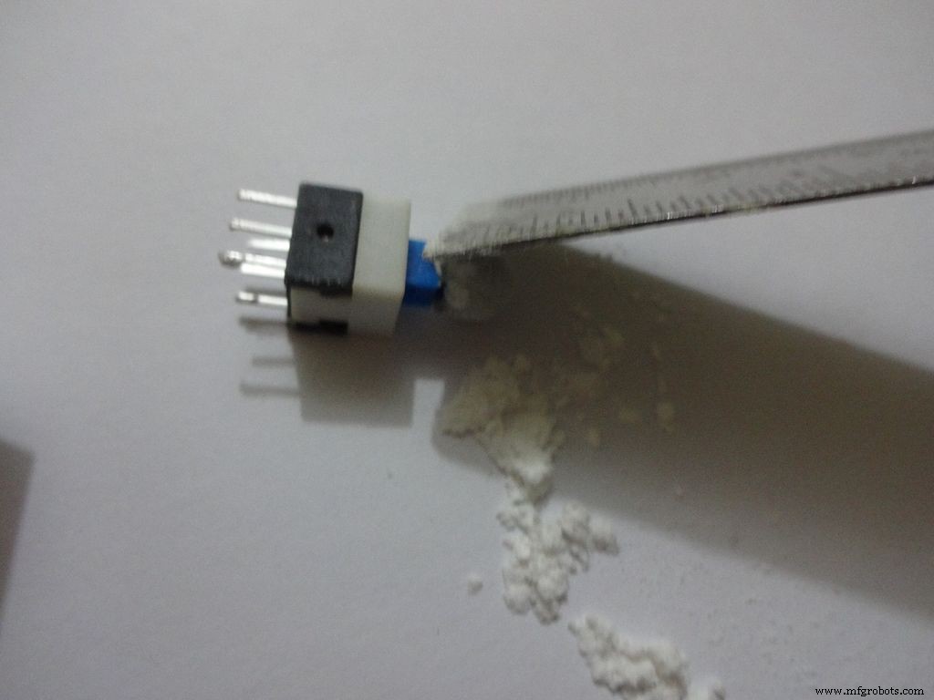
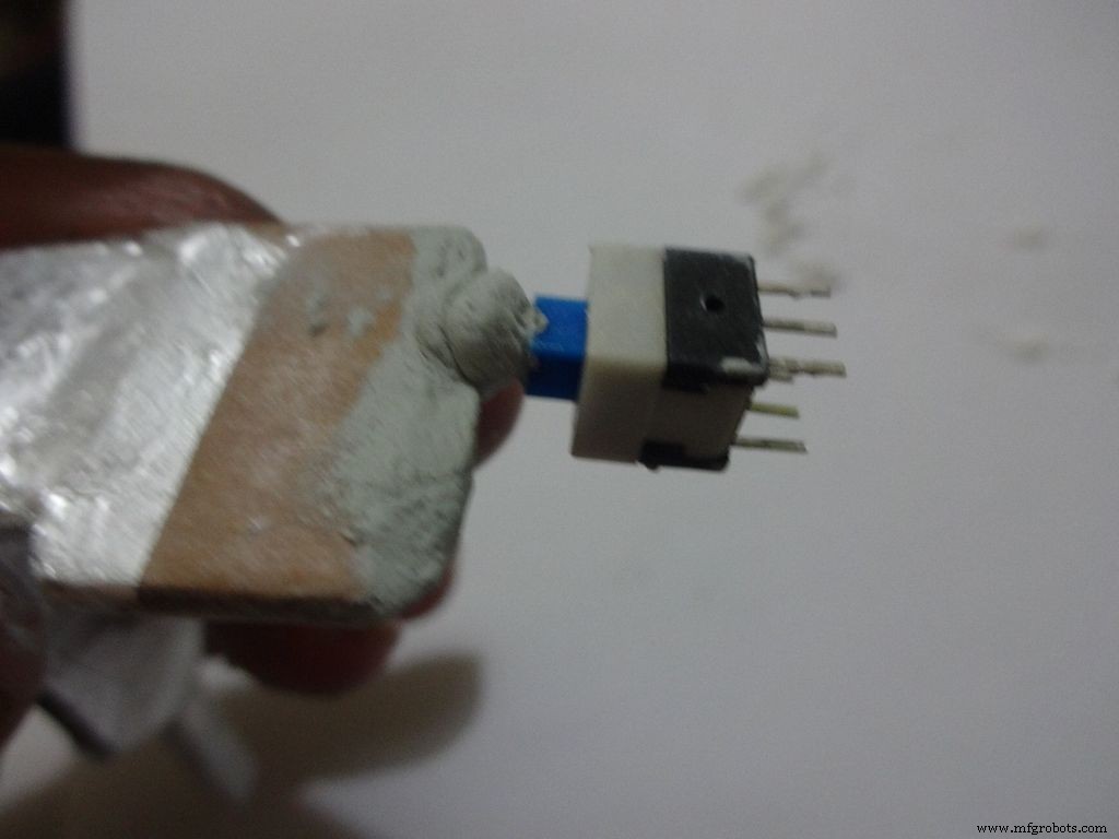
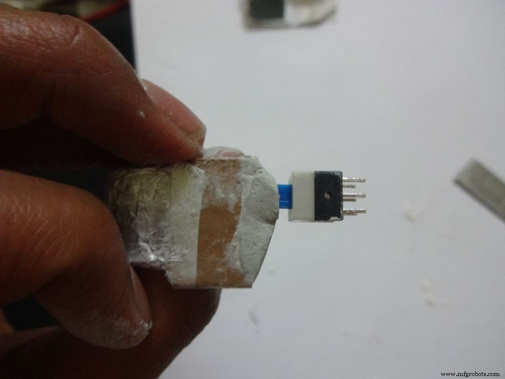
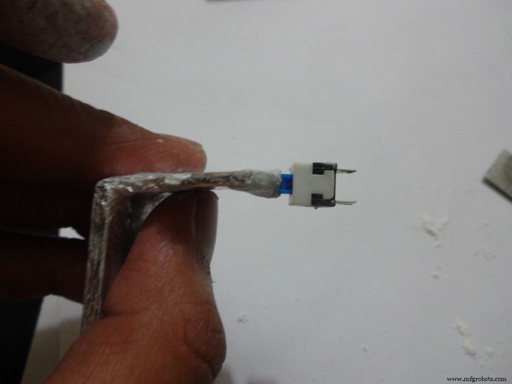
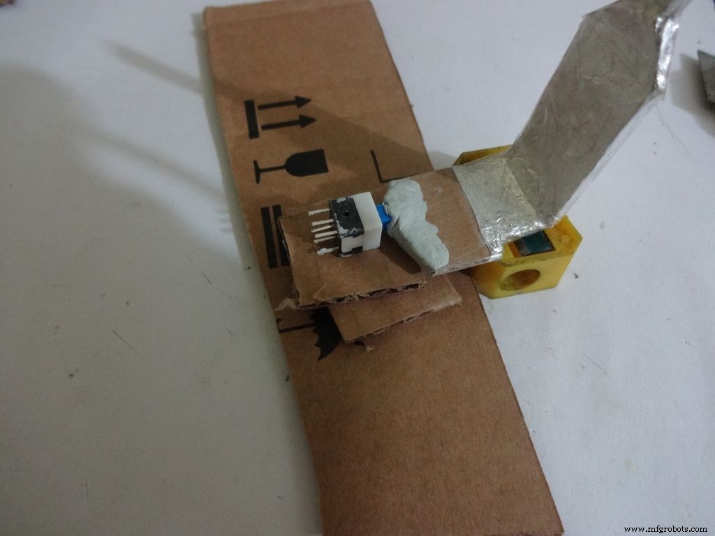
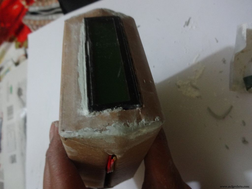
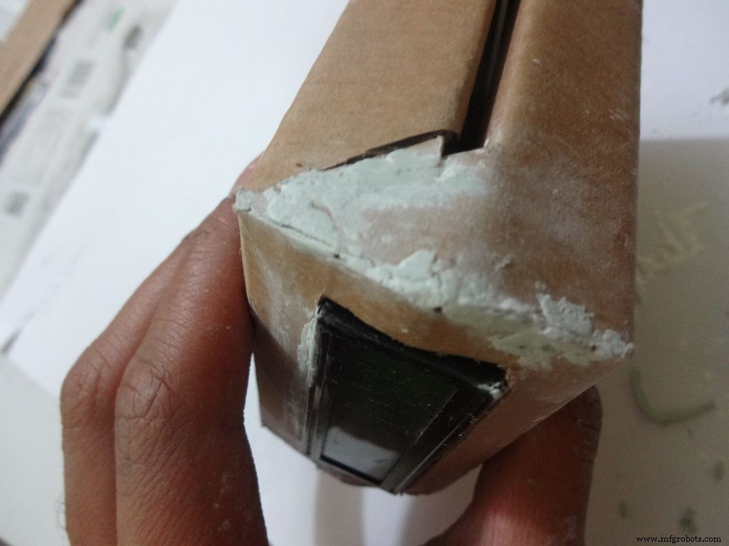
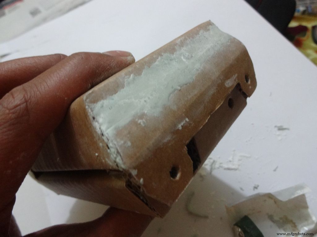
Measure and cut the power switch leg by properly keeping it in place. Temporarily stick the other pins with tape to get the pin1 position right.
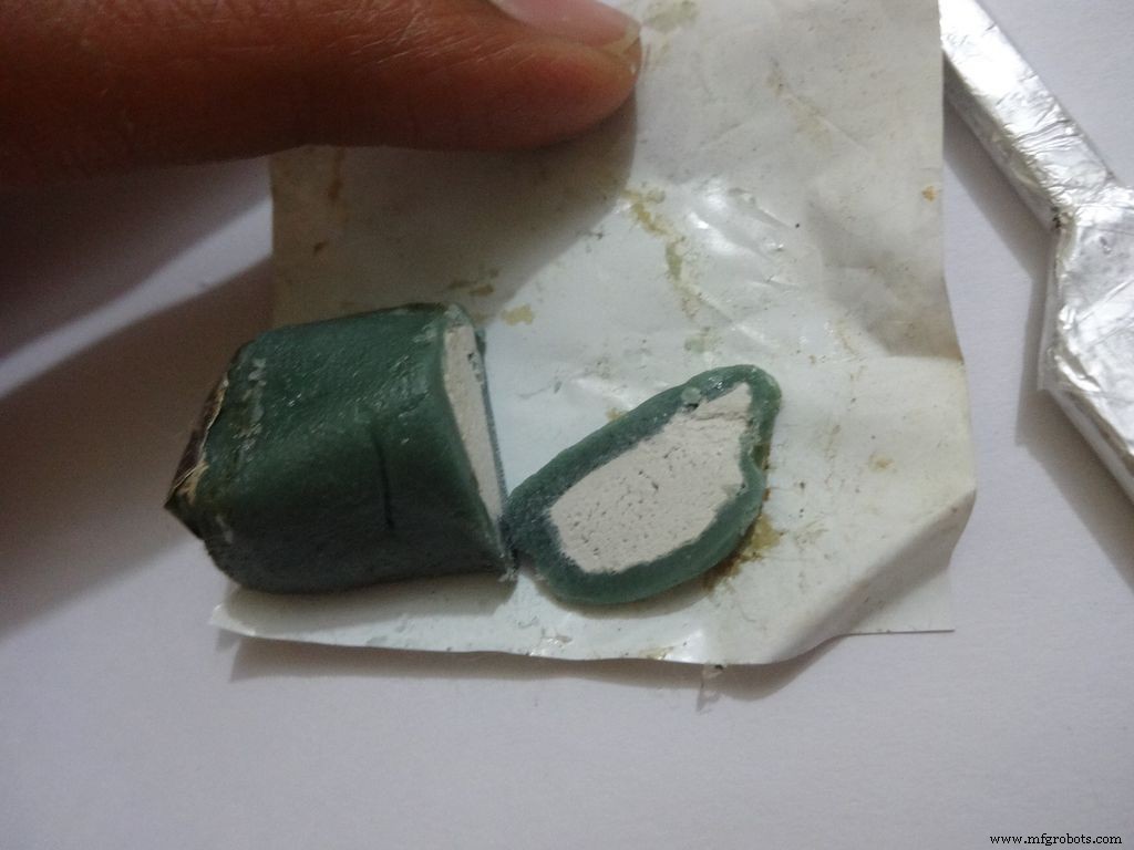
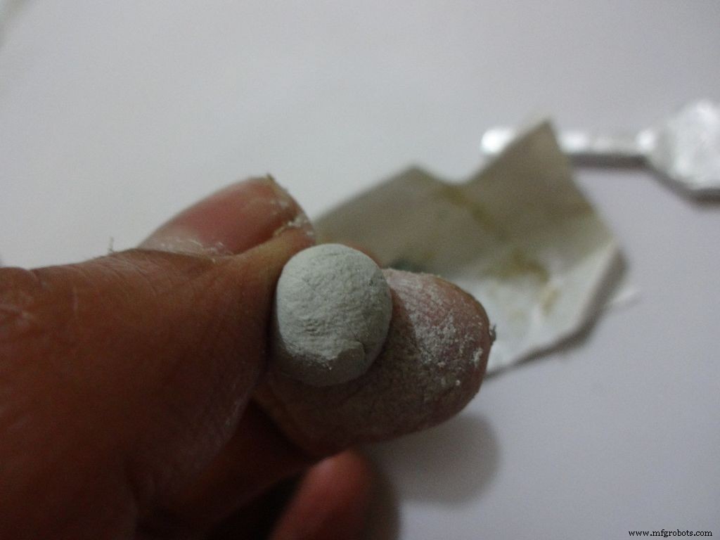
Mix the m-seal(epoxy putty sealant, gets very hard when it dries) well. Put it as shown in the images and use powder+flat surface to shape it. Let it dry.
Also fill any gaps left in your case.
Note:We cant use hot glue here as it is rubbery and the switch needs to be stuck with some strong brittle material.
Step 26:Power switch to PCB
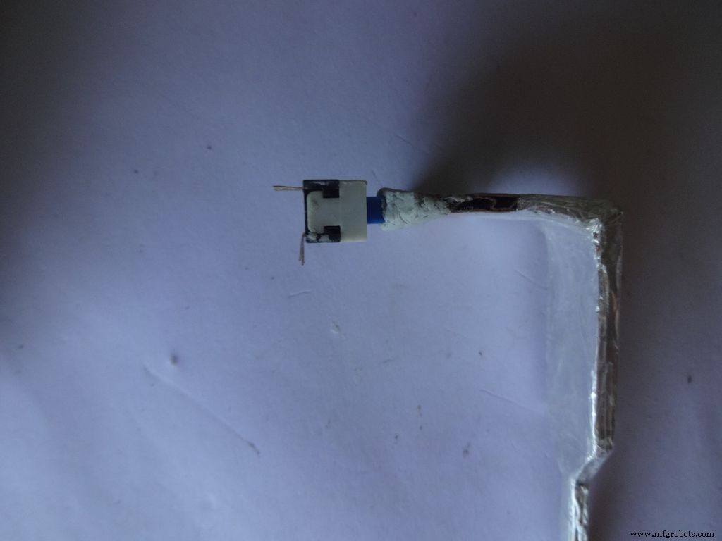
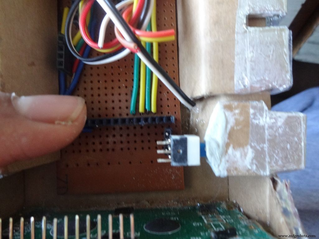
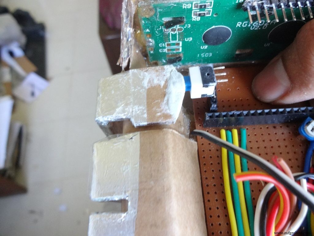
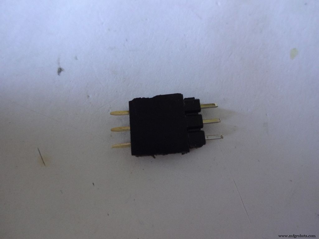
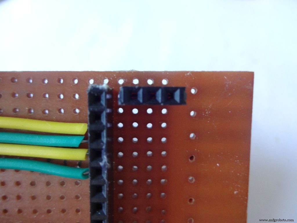

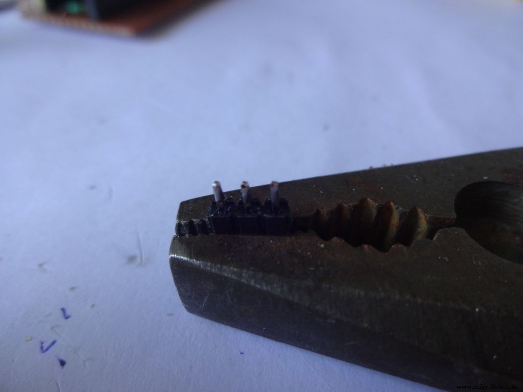
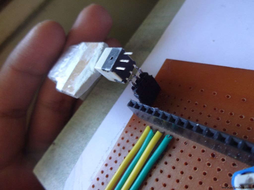
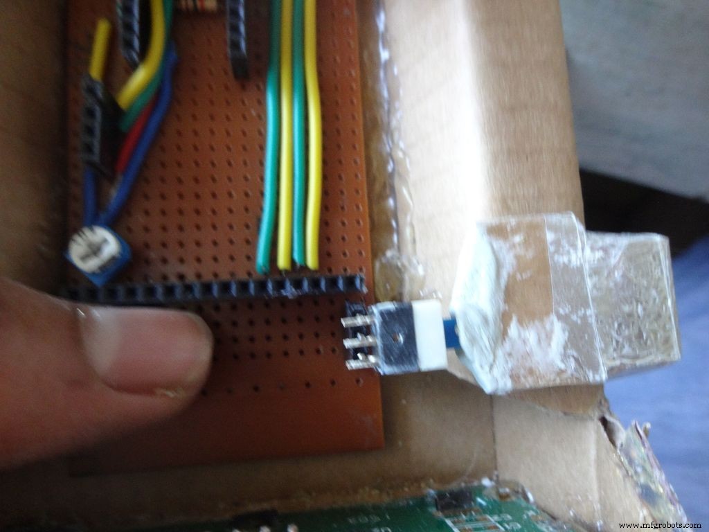
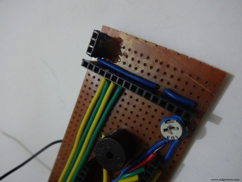
After The m-seal dries, place it in to check if everythings alright.
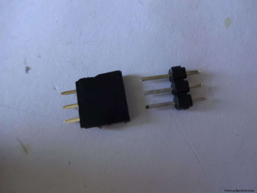
Cut 3pins of female and male headers place it on the PCB such that it aligns with the switch pins. Solder the female part.
Tin the switch leads and the male header pins, join them. See if it fits at the right place.
Try pushing the switch on and off after placing a finger behind the switch for support. We will add a support rod later on.
Connect a side pin of female header(power switch) to Vin. I realised this late and had to undergo lots of trouble.
Secure the header Pin with hot glue.
Step 27:Making the USB Port

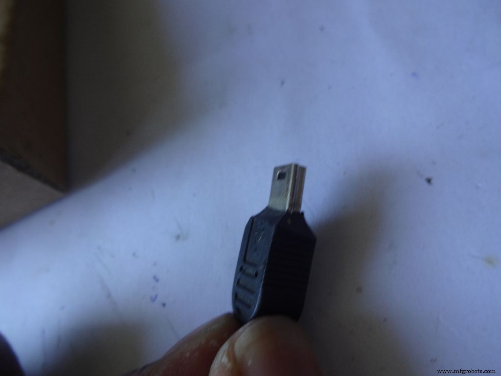
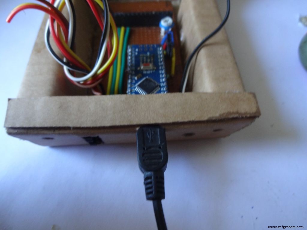
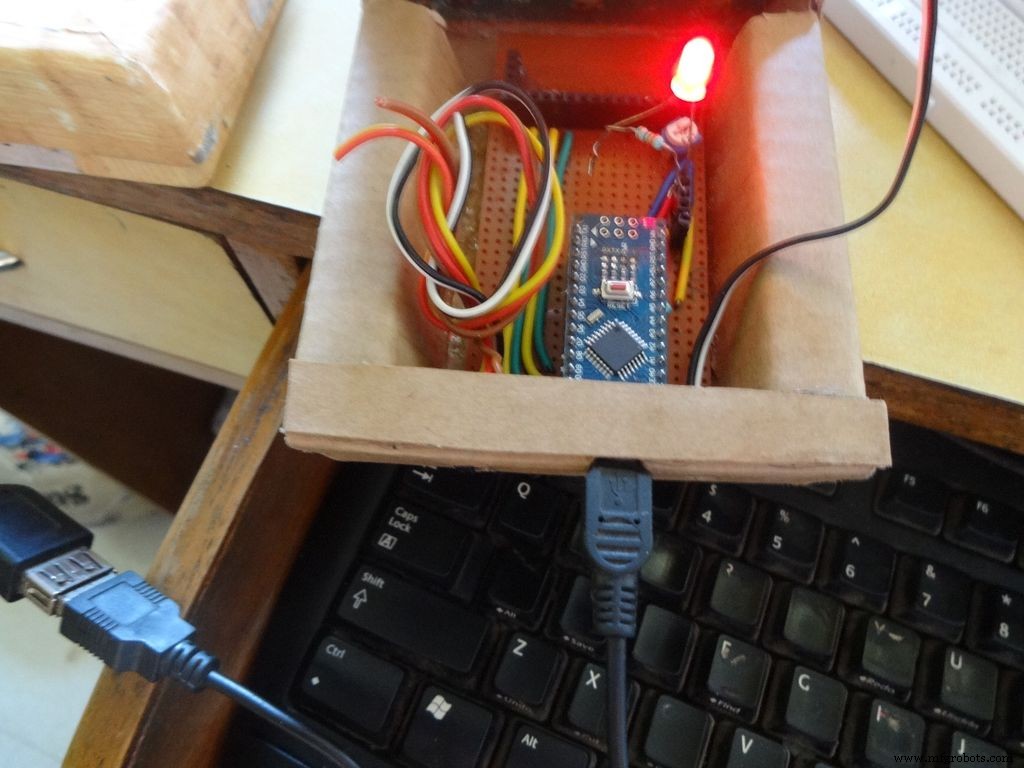
Put the PCB properly in (with Arduino) and cut a rectangle for the mini USB port.
Remove some plastic from the USB cable so that it fits the Arduino properly. Test whether connection is proper.
Step 28:Some other things...
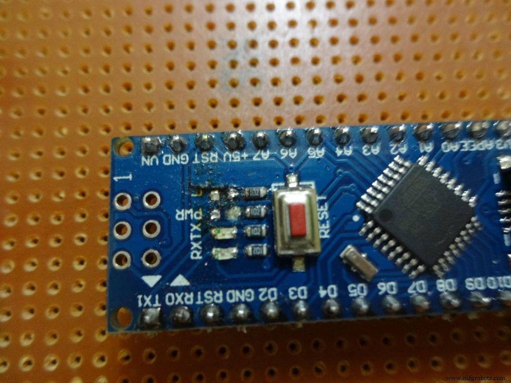
I removed all the LEDs from the Arduino Nano and also the power LED on my RTC module. These consume unnecessary power, which matters if you are operating on a battery.
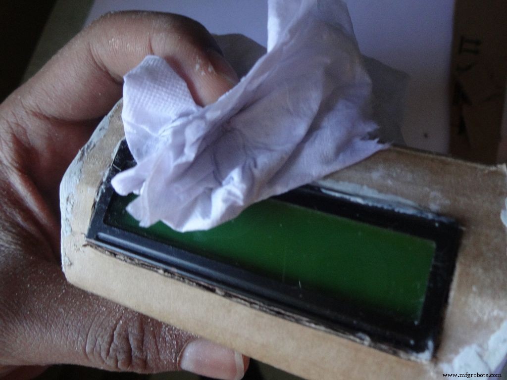
Sand the dried m-seal so that it mixes smoothly with the cardboard. Clean the powder with a wet paper napkin before painting.
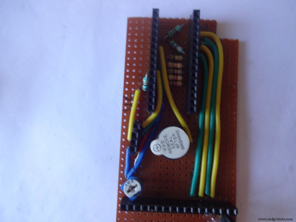
I also added a buzzer which may be used for some functions. Buzzers are sensitive, don't use too much heat while soldering!
Step 29:Time to paint!
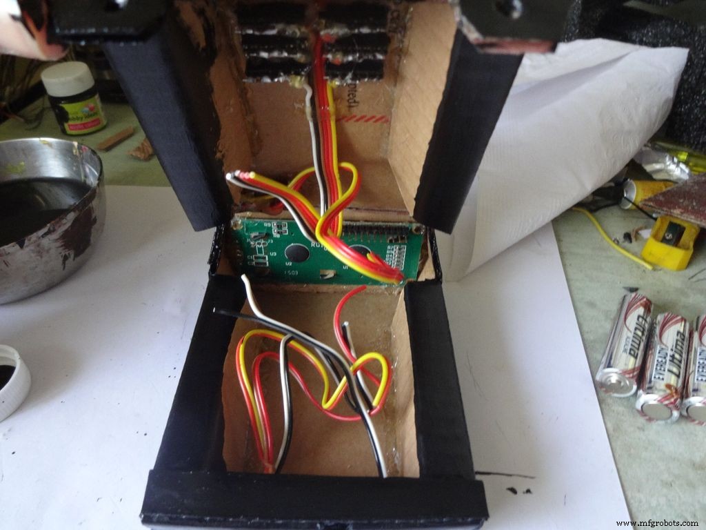
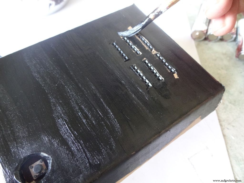
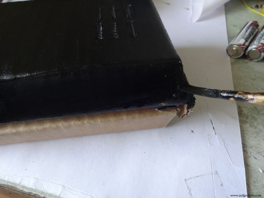

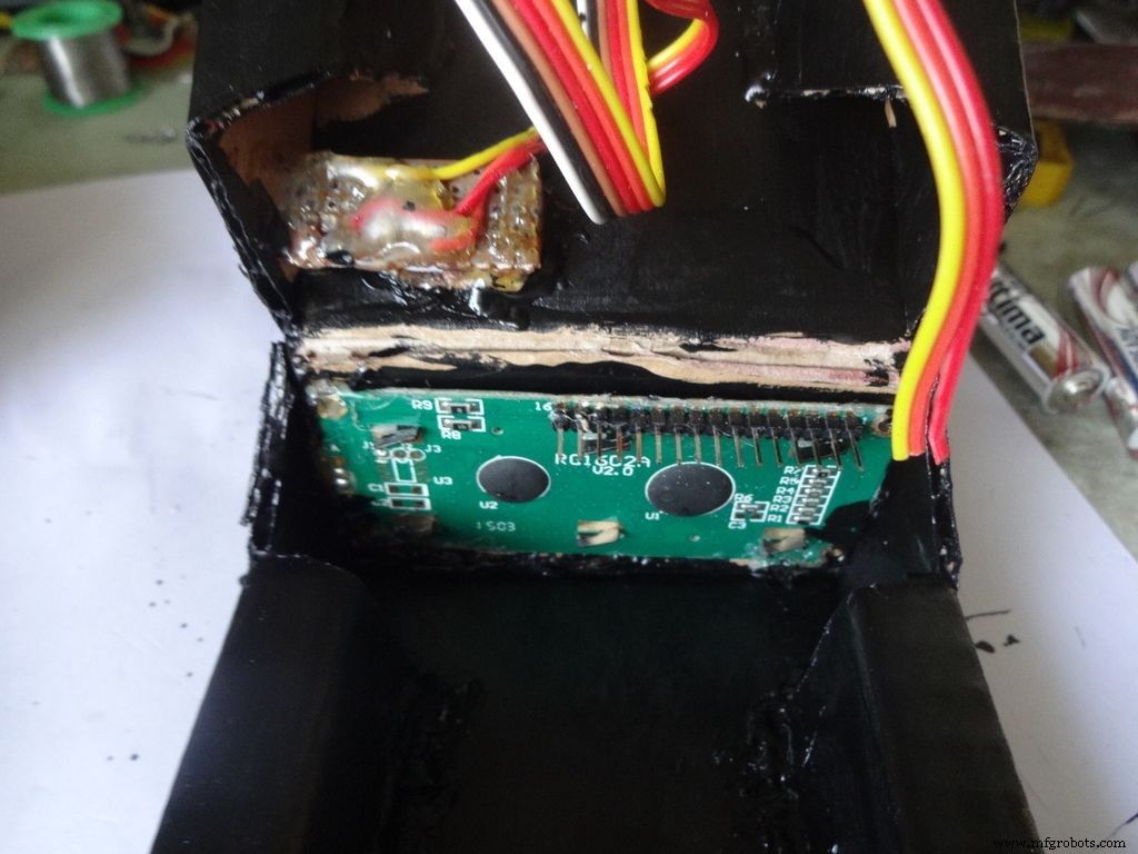
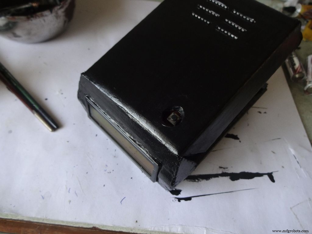
Dont use direct thick paint while painting, this cases brush patterns to appear. Use sufficient water.
Make sure no tiny bubbles are formed. These form when you dab the brush too much.
Dont paint the cover hinge, the paint will restrict it.
This is just a base coat. Another layer of paint will be added while finishing up.
Step 30:Soldering all the wires
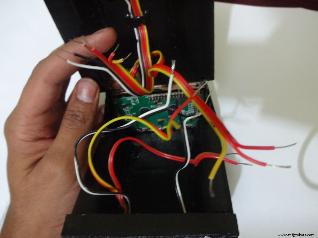
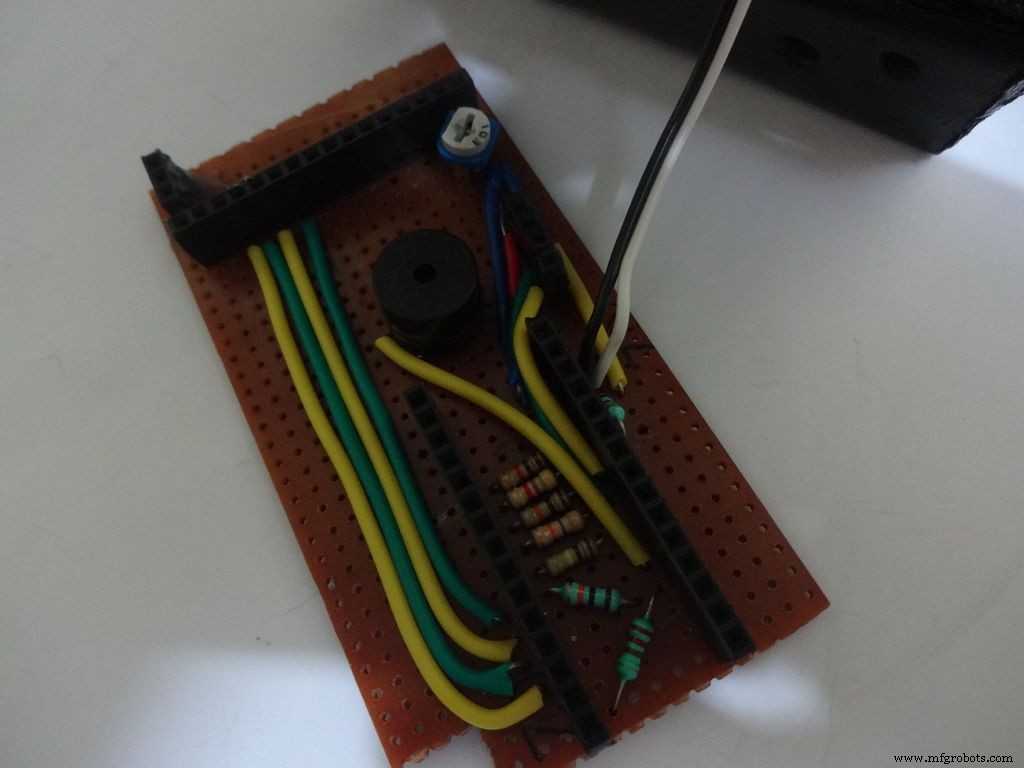
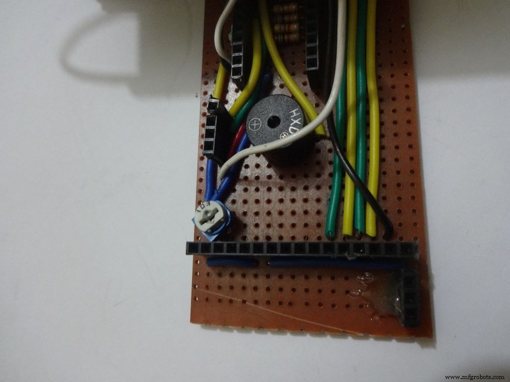
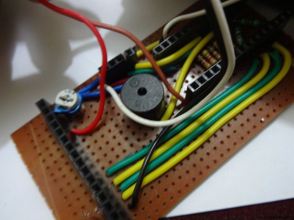
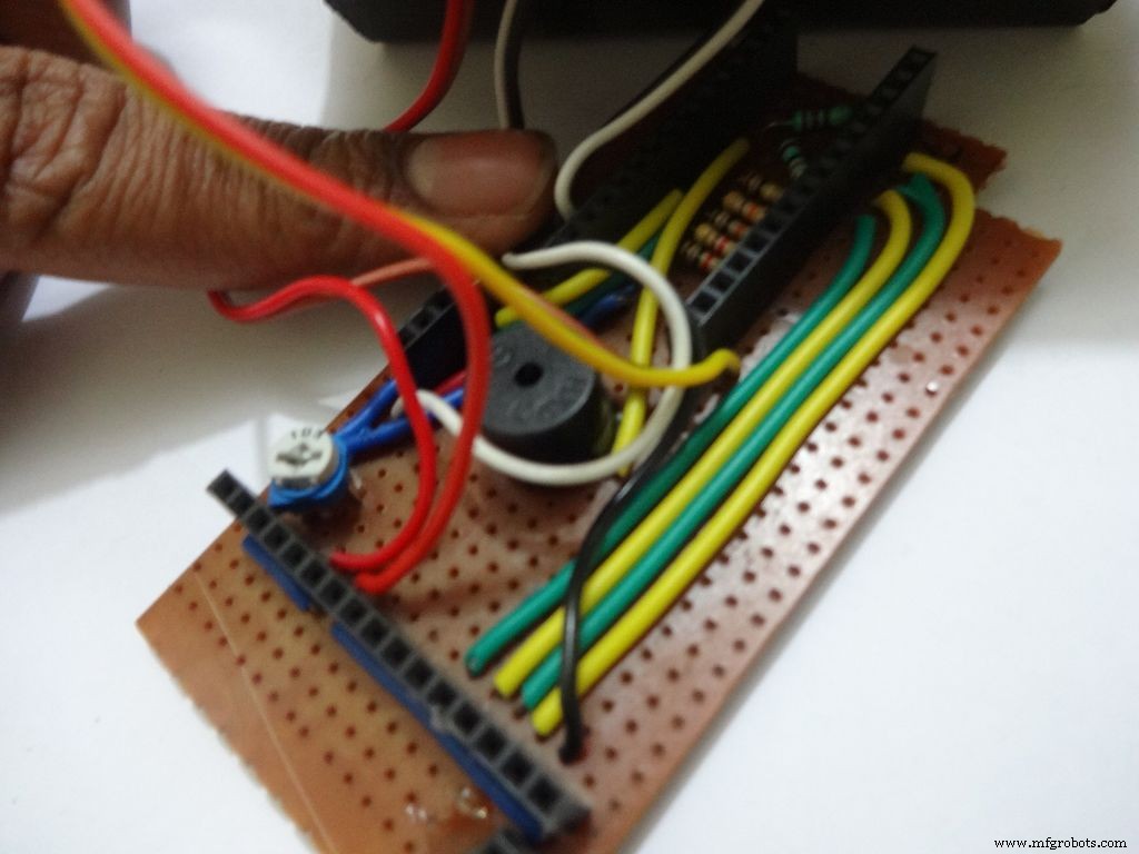
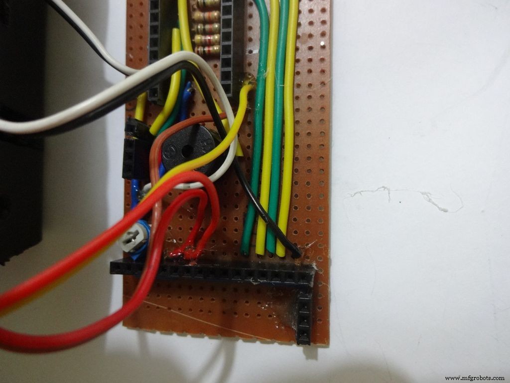
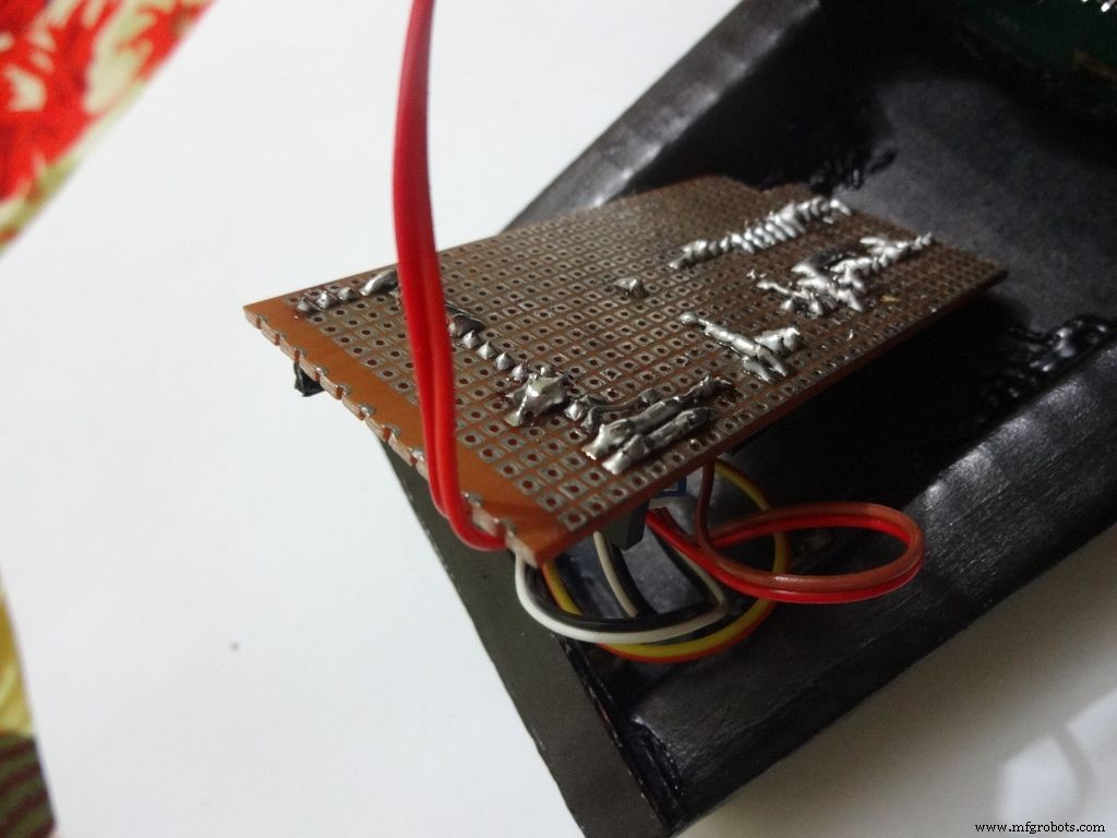
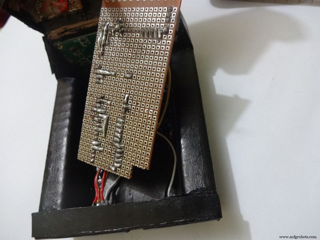
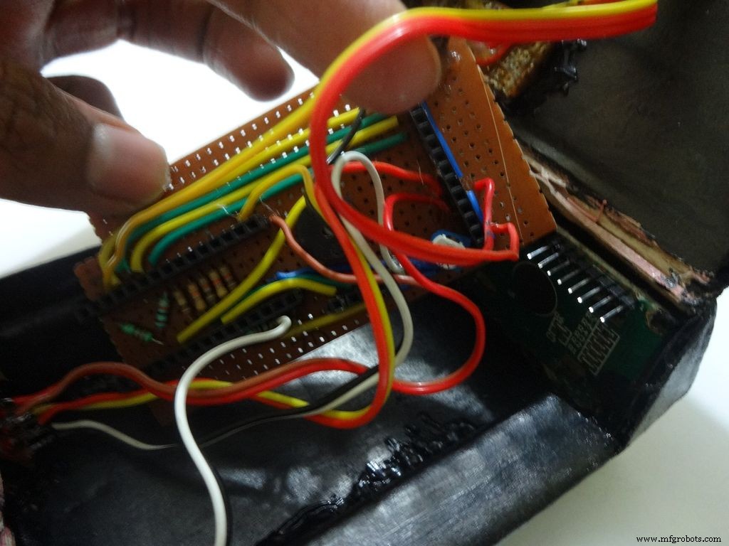
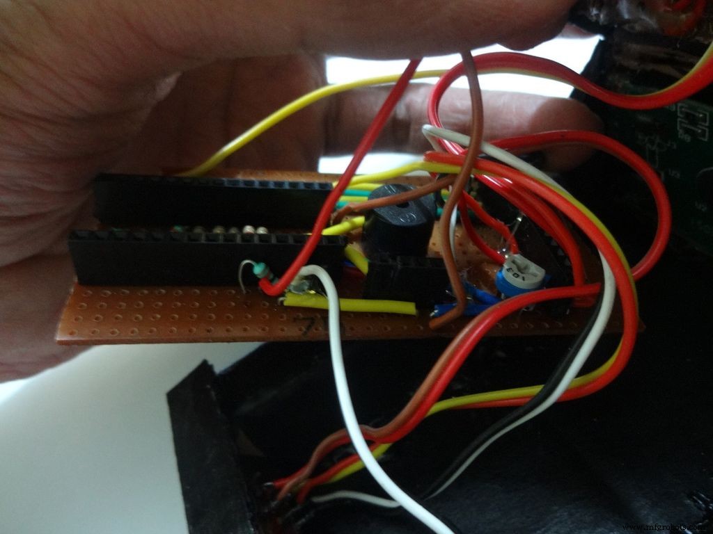
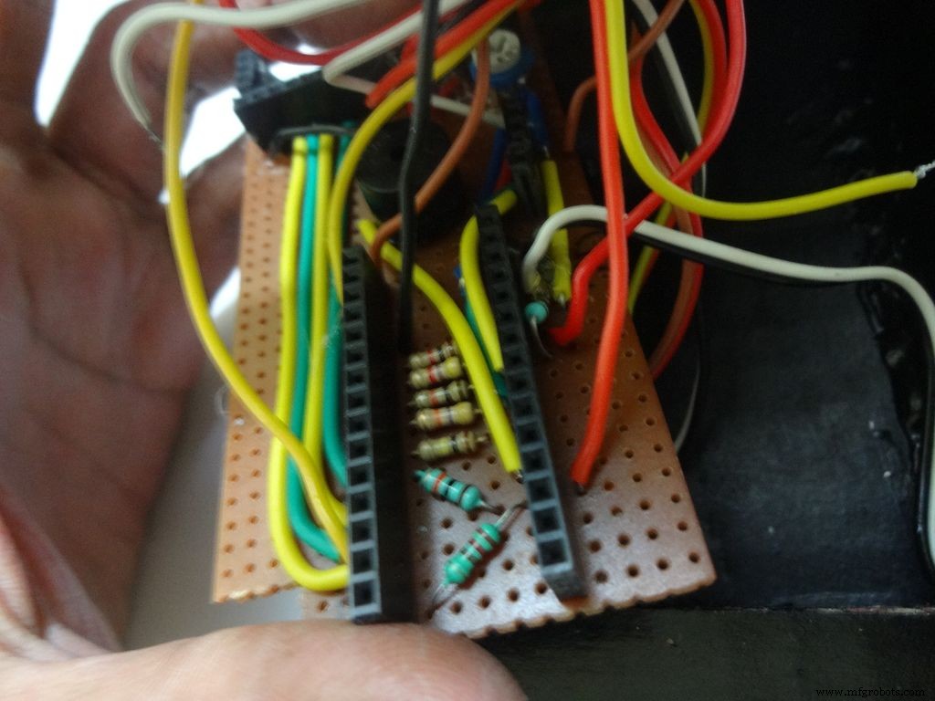
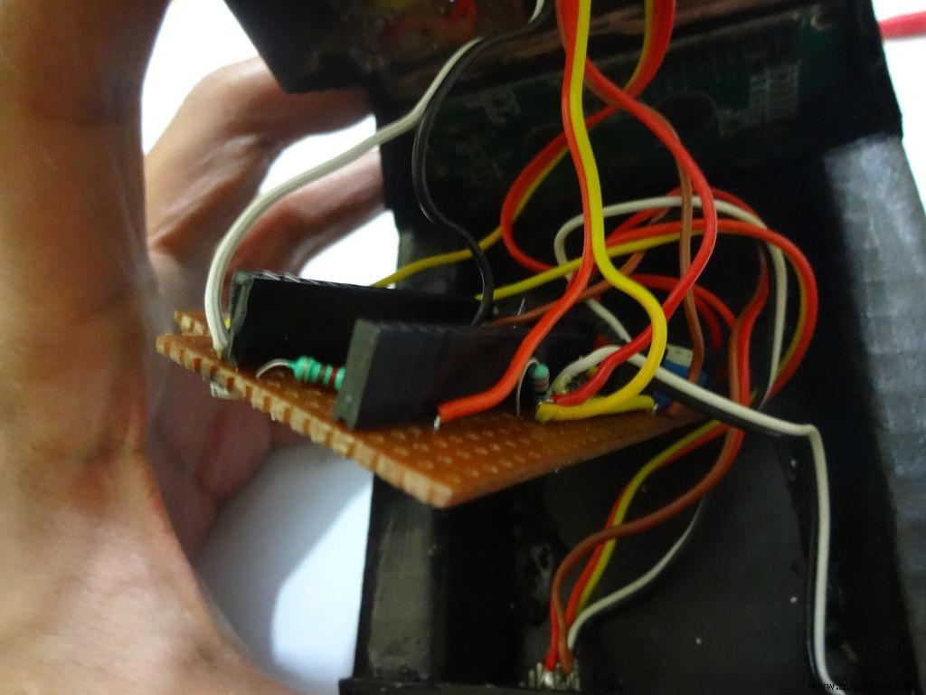
Make sure you refer the circuit design before making any connections.
First connect the reset switch, one end to RST and one end to GND.
Then, the backlight switch. One end to +5V and other end to 'A' or Anode of the backlight LED. Also connect 'K', Cathode to GND.
Next is the RS switch, connect one end to RS and other to pin D1(TX).
And finally the Enable switch. Connect one end to 'E' or Enable and other end to pin D0(RX).
Switches
Where to?
Reset - pushbutton RST and GND Backlight - slide +5V and A RS - slide D1 (TX) and RS Enable - slide D0 (RX) and E
Note:Pins D0 and D1 are connected through switches as keeping them connected sometimes causes problems while using Serial(for debugging).
This completes the base wiring. Apply hot glue after double checking the connections.
Then connect the 3 wires of mode change button:The 10k pulldown resistor to GND. 220 Ohm resistor to pin D11 and input pin to +5V or VCC
Finally connect the 6 wires from the test slots to their appropriate places(shown in images).
Positive
Negative
Resistance Test A7 GND Capacitance Test A0 GND Diode Test A6 D12
Note:All the +5Vs and GNDs are same and hence connect to most convinient spot.
Step 31:Adding the battery case
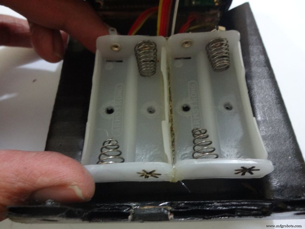
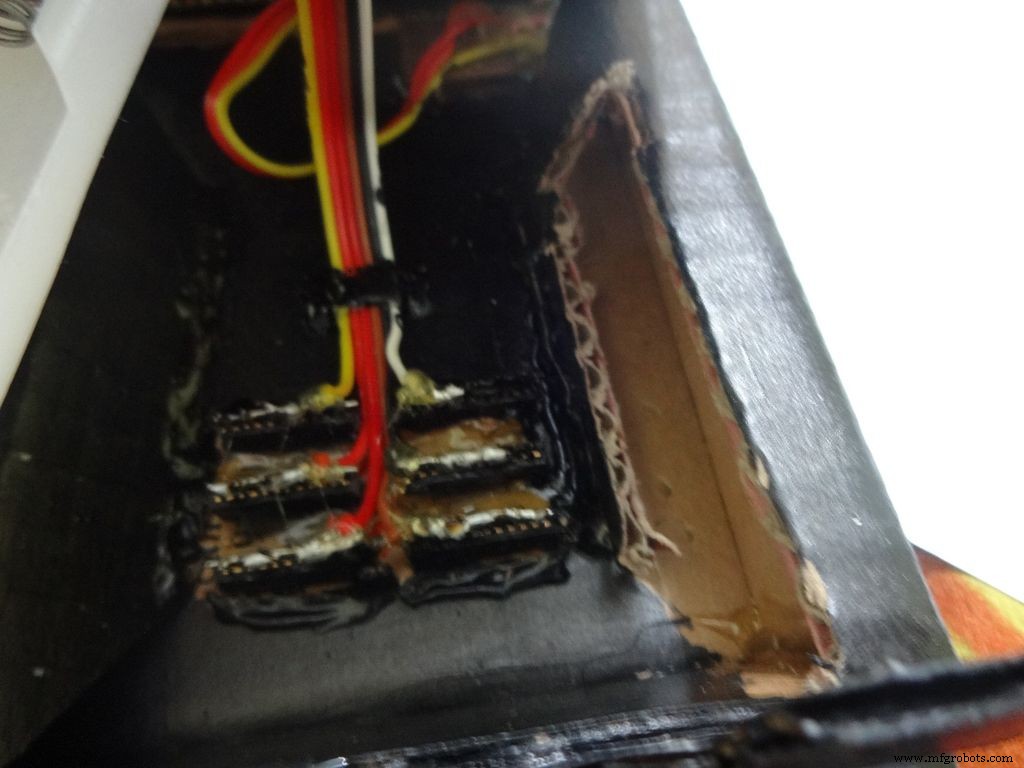
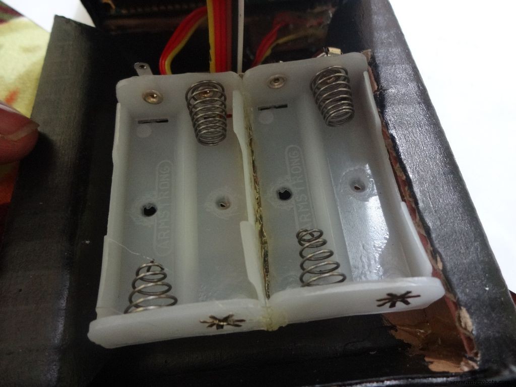

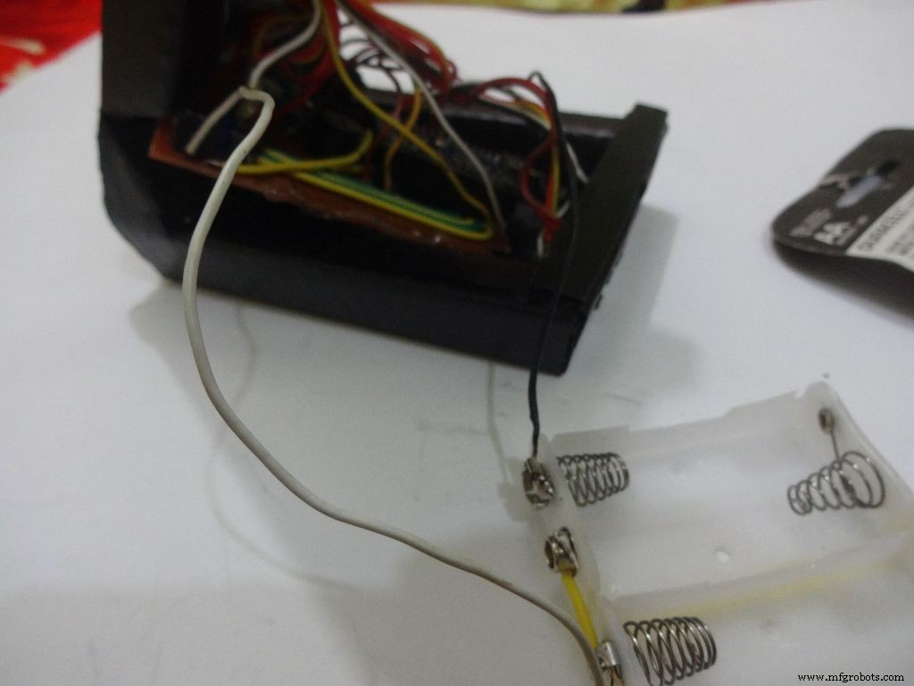
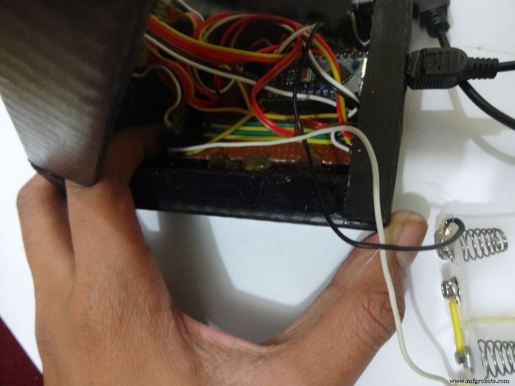
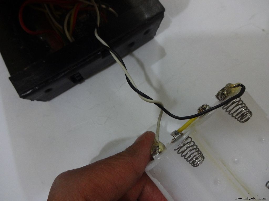
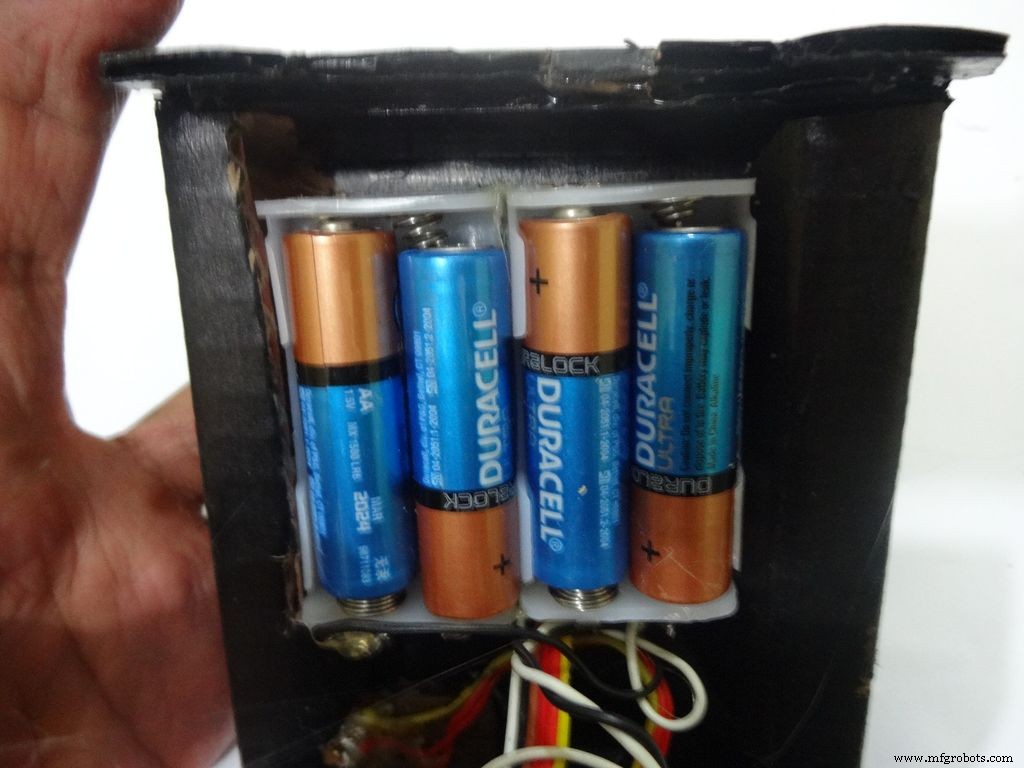
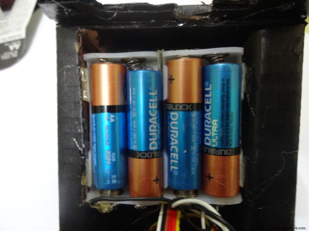
Place the battery case at the top cover, make cuts to place it inside such that the cover can be closed properly.
Solder Wires to the case, strip and tin them. Solder the positive end to the middle pin of power switch and negative end to ground.
Glue the PCB to the base after making all the connections.
Twist the wires and place them in position. Insert batteries(the case expands a bit on inserting batteries) and glue the case to the cover.
Step 32:Adding the Legs
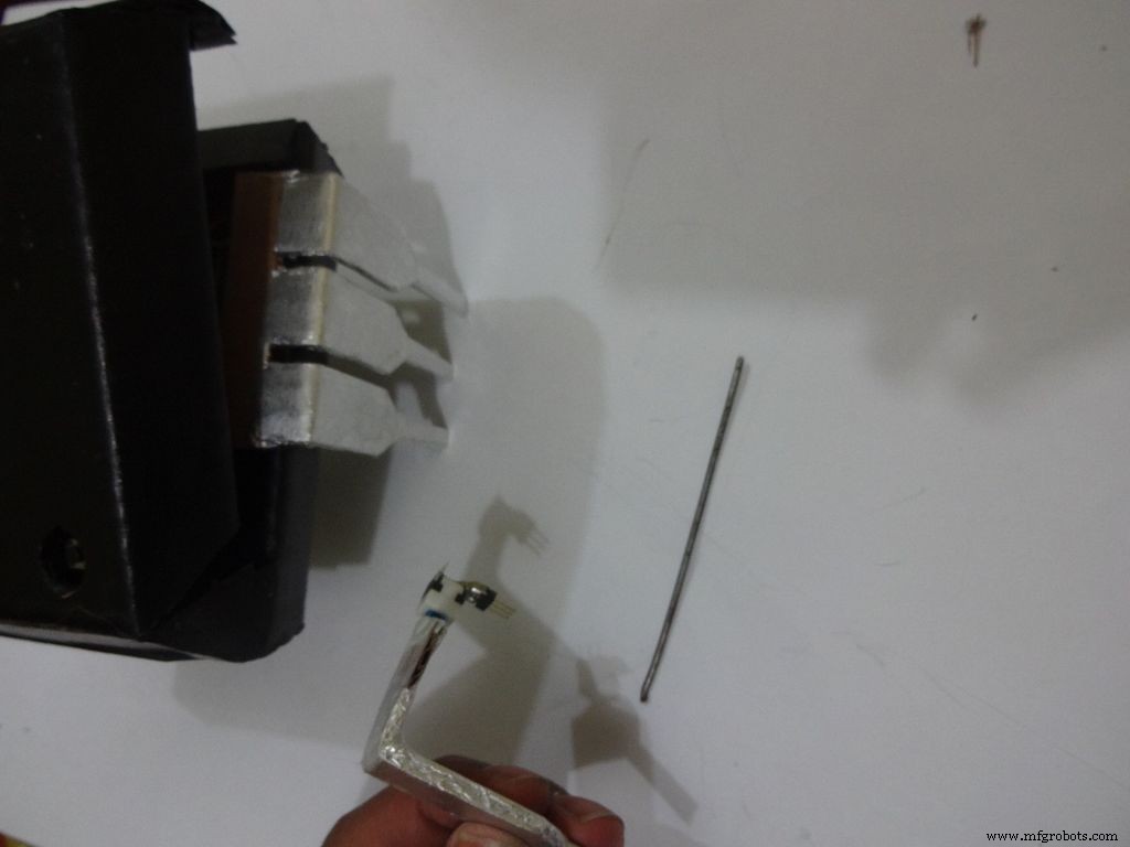
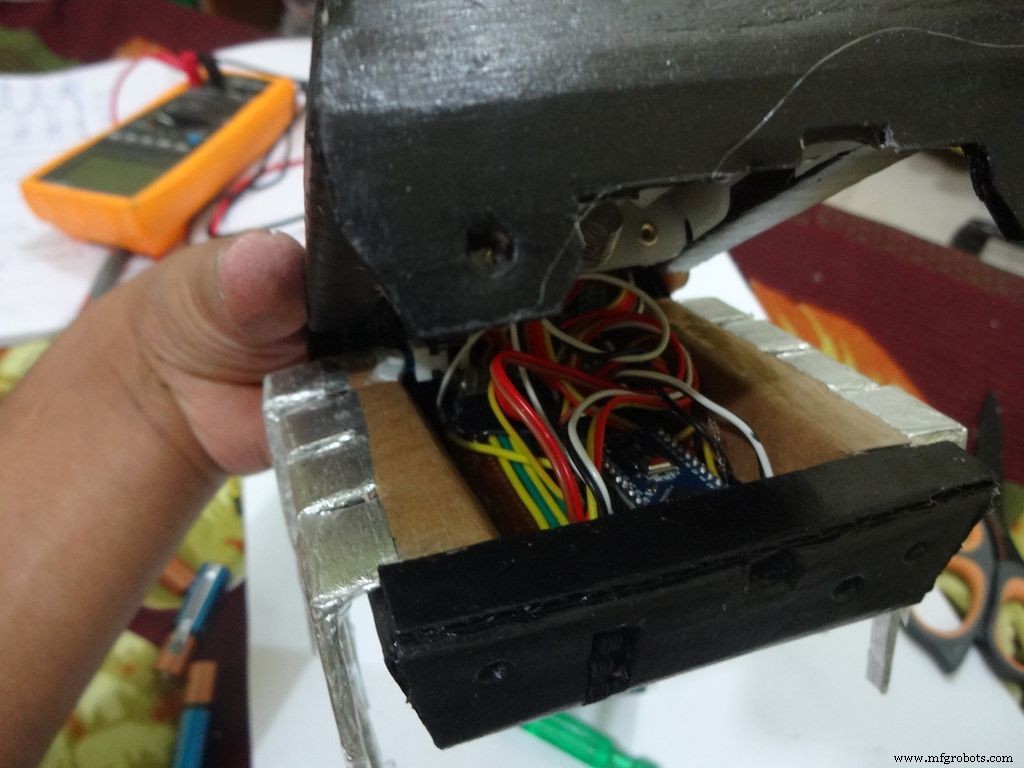

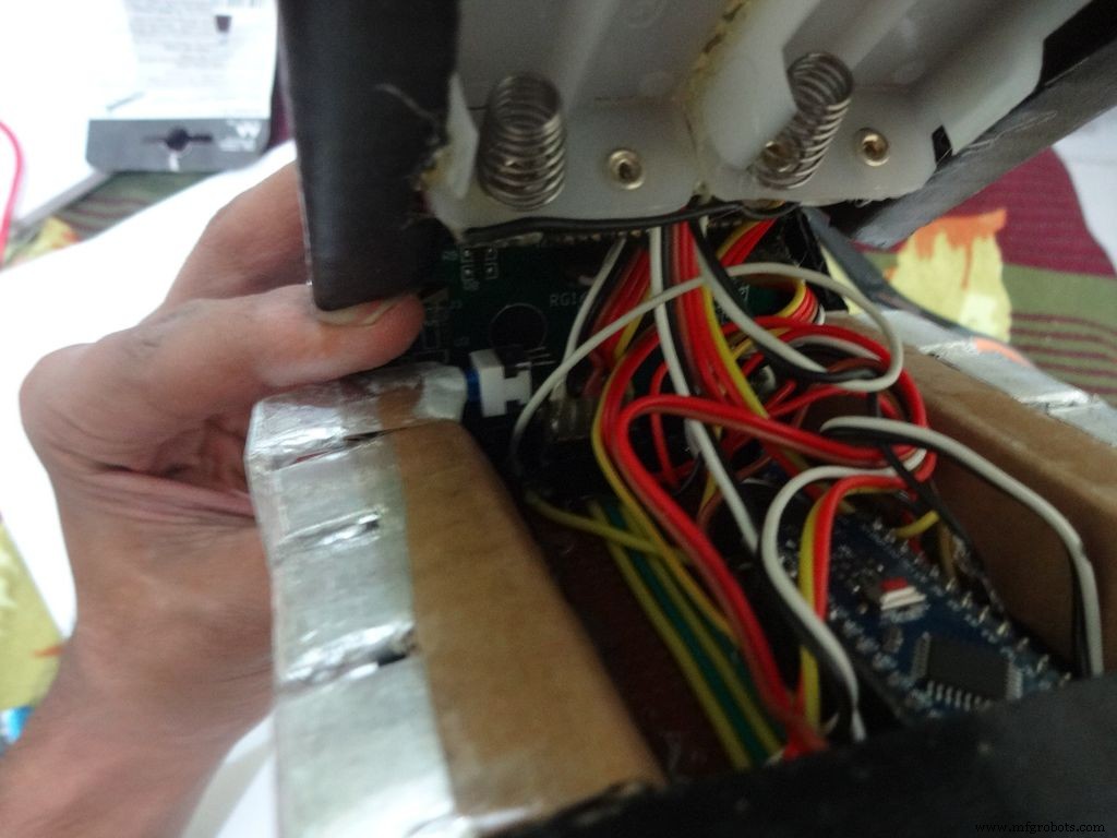
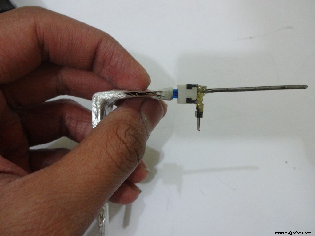
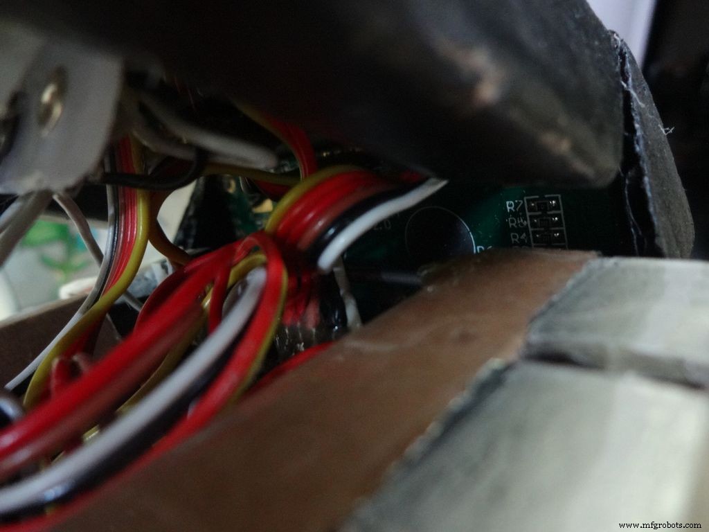
Cut the inner part of legs so that it fits in properly. Stick it it place.
Put the power switch pin in to check if it fits in perfectly. Remove it, add a metal rod, piece of wood or anything strong of proper length that will prevent the switch from moving back. Glue it in place.
Check the switch, it should be turning on/off smoothly.
Switch on the IC and test all the functions. If its not working skip to the troubleshooting section.
Step 33:Finishing up!
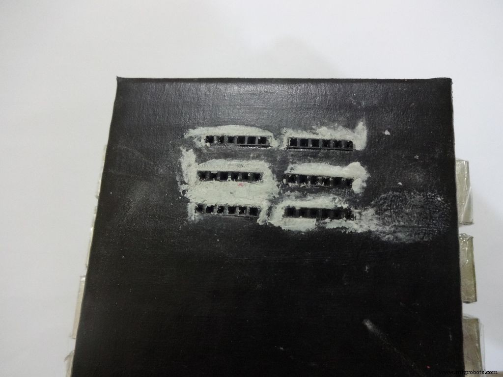
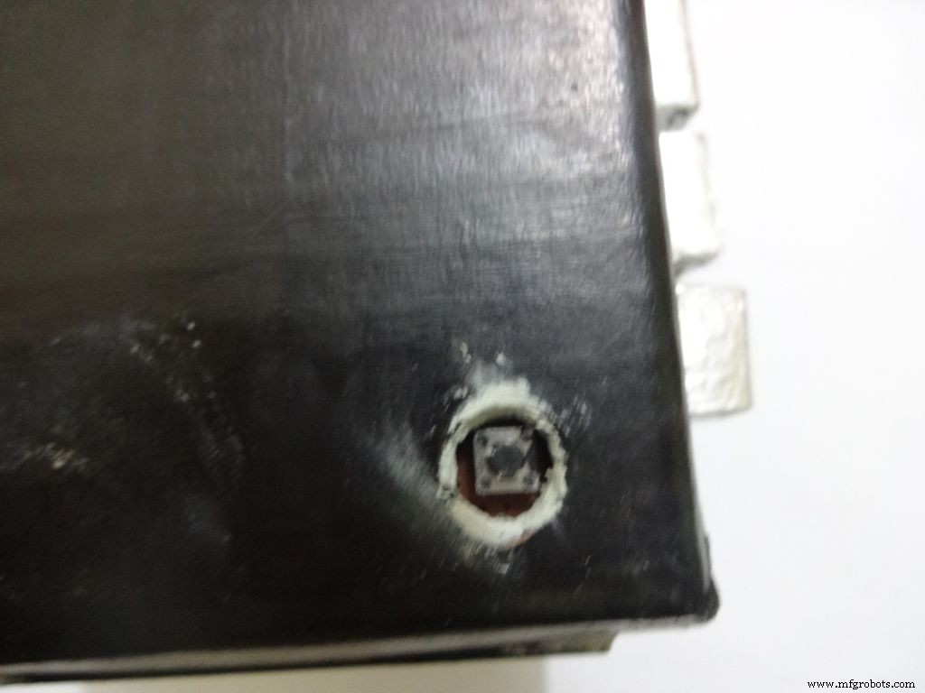
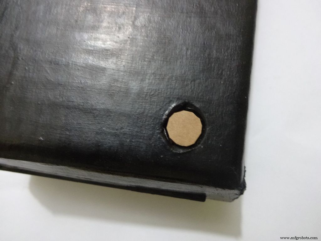
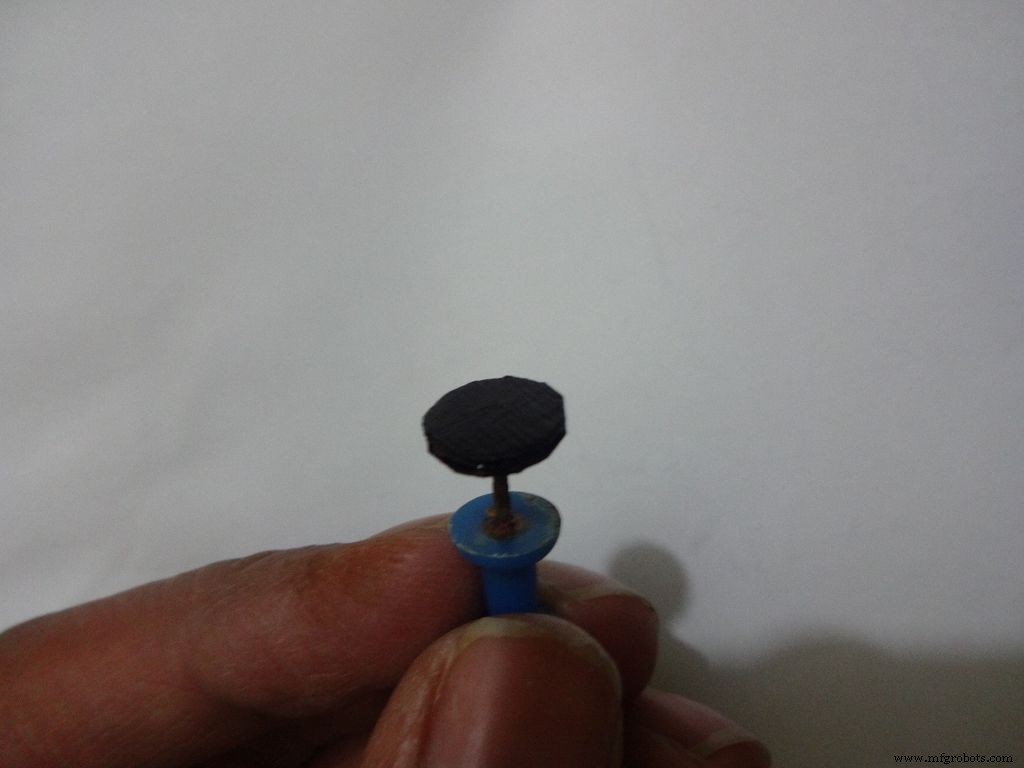
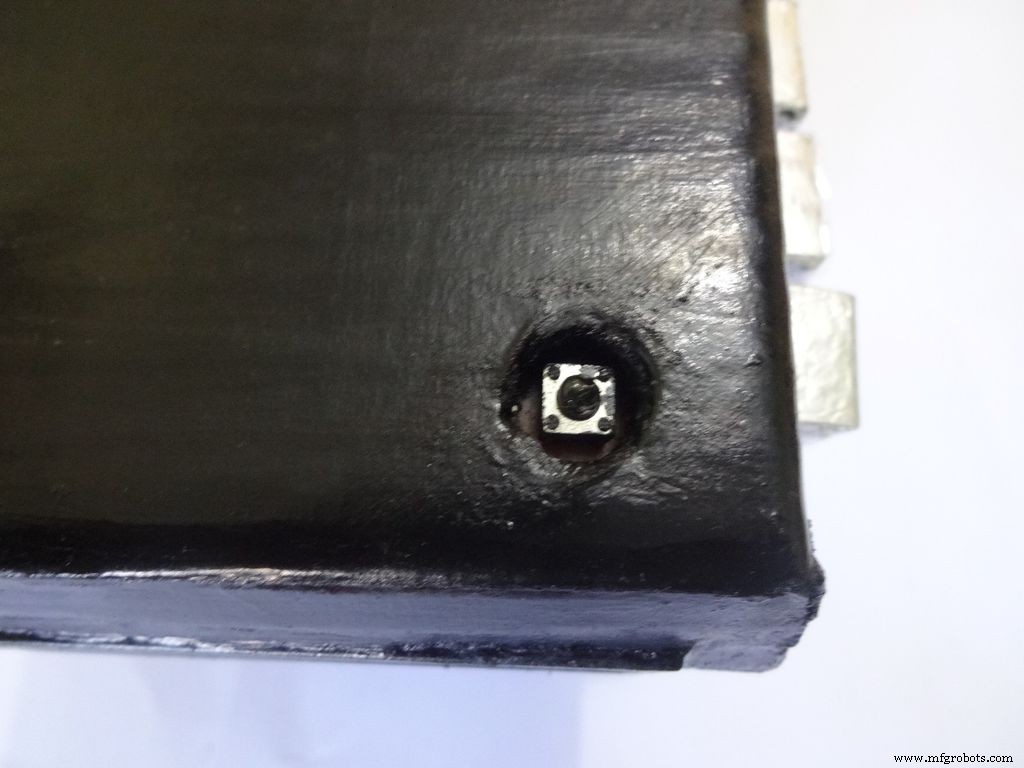
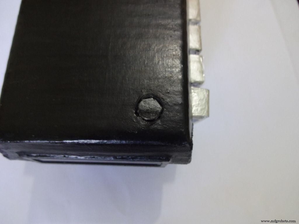
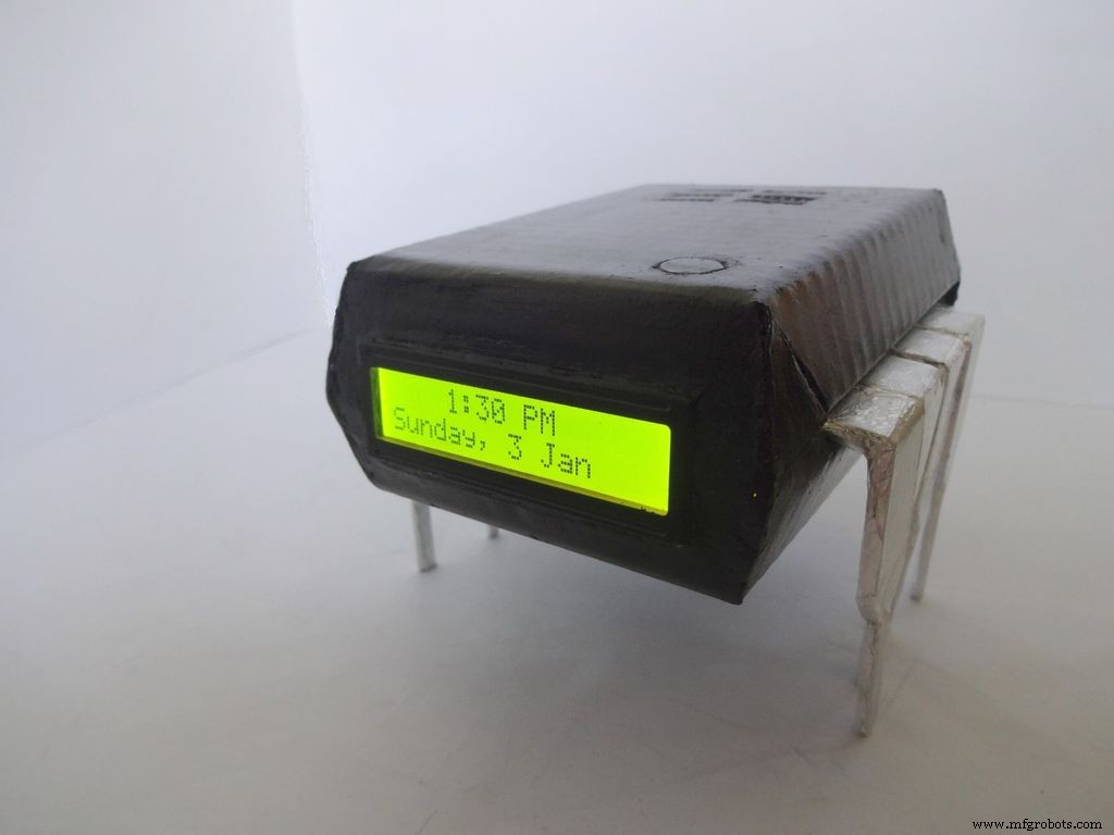
Use M-seal (or equivalent) to fill any small gaps around the testing area and the mode change button. After drying, sand it well and apply a second layer of paint.
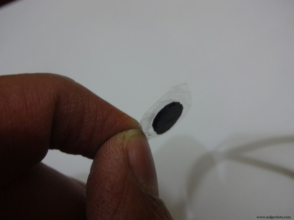
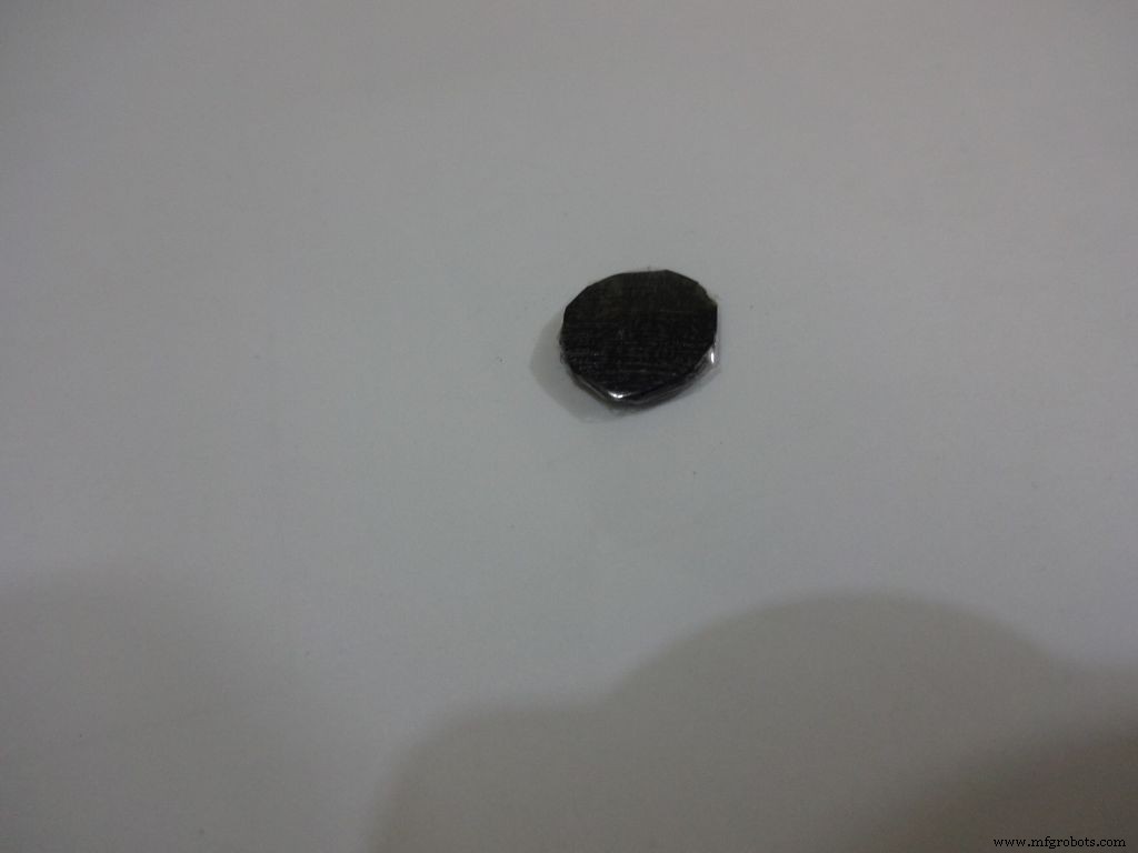
Make the button with a small piece of cardboard, paint it black and cover it with tape(gives a shiny finish). Apply a tiny drop of glue and stick the button in place.
Step 34:Problems and Troubleshooting
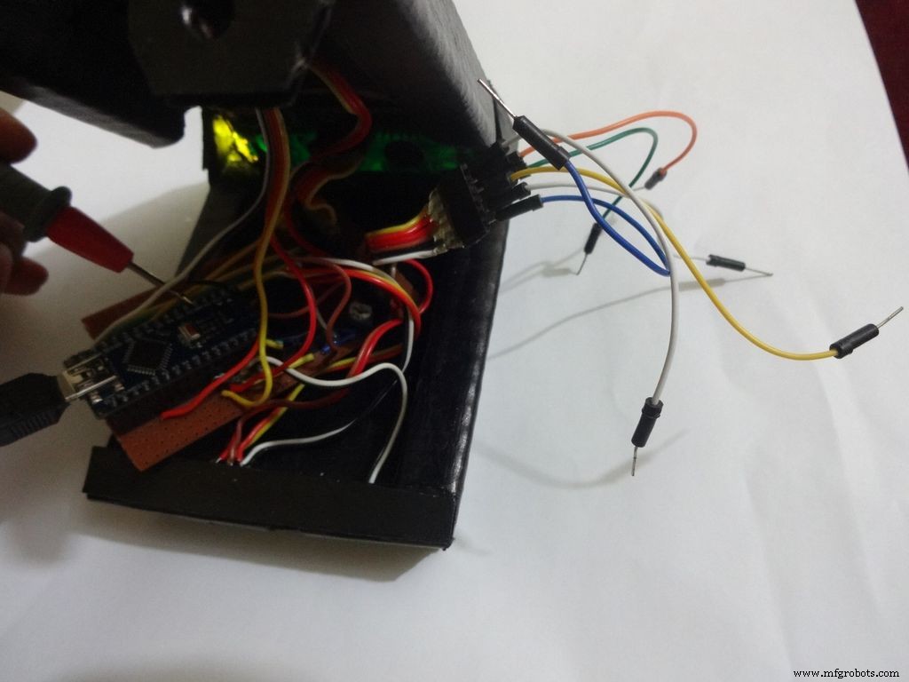
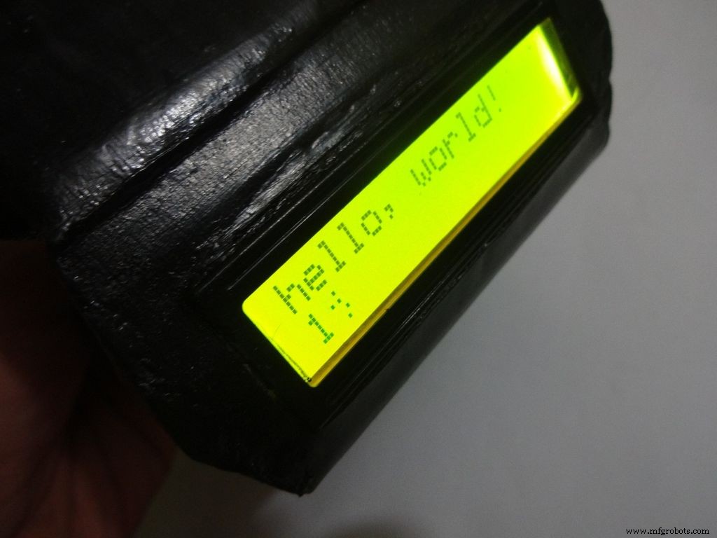

Do everything correctly. This is the most boring most of any project and you dont wanna get here just because you soldered the wrong pins!
- Recheck every soldered joint and ensure that it isnt touching the adjacent one. Use the multimeter continuity test for help.
- After cutting component/jumper leads make sure the cut lead doesnt fall underneath the PCB. This may lead to unwanted shorting soldered joints.
- Write down anything you need to remember in a book, don't trust your memory.
- If LCD is not displaying, make sure the contrast is adjusted properly. Also make sure the pin0 and 1 switches are turned ON. Check all the pin connections from LCD to Arduino with continuity test. Use breadboard jumpers wherever your mutimeter cant reach.
- Upload the hello world LCD program to see if the problem is in the code.
- If a particular function is not working, check its connections and tally it with the code.
- And most importantly, keep your curious pets with their evil minds away from your workspace! :p
Step 35:Things I did, some mistakes I made
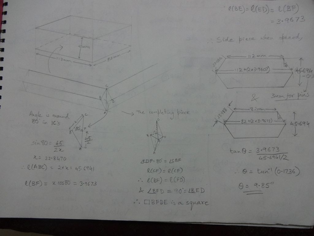
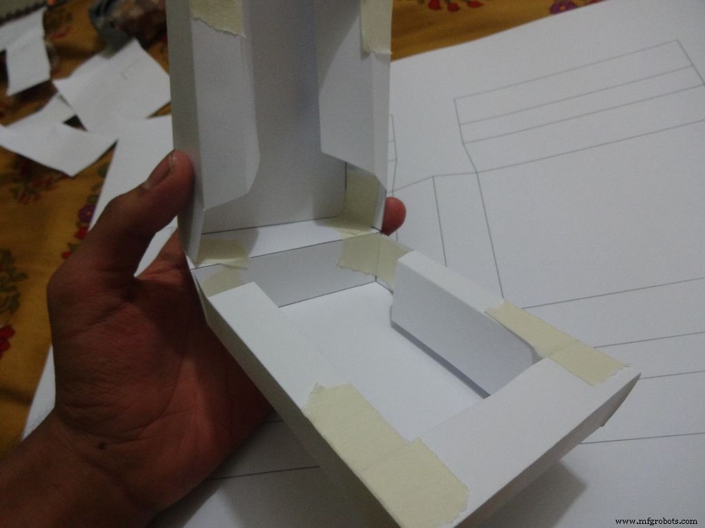

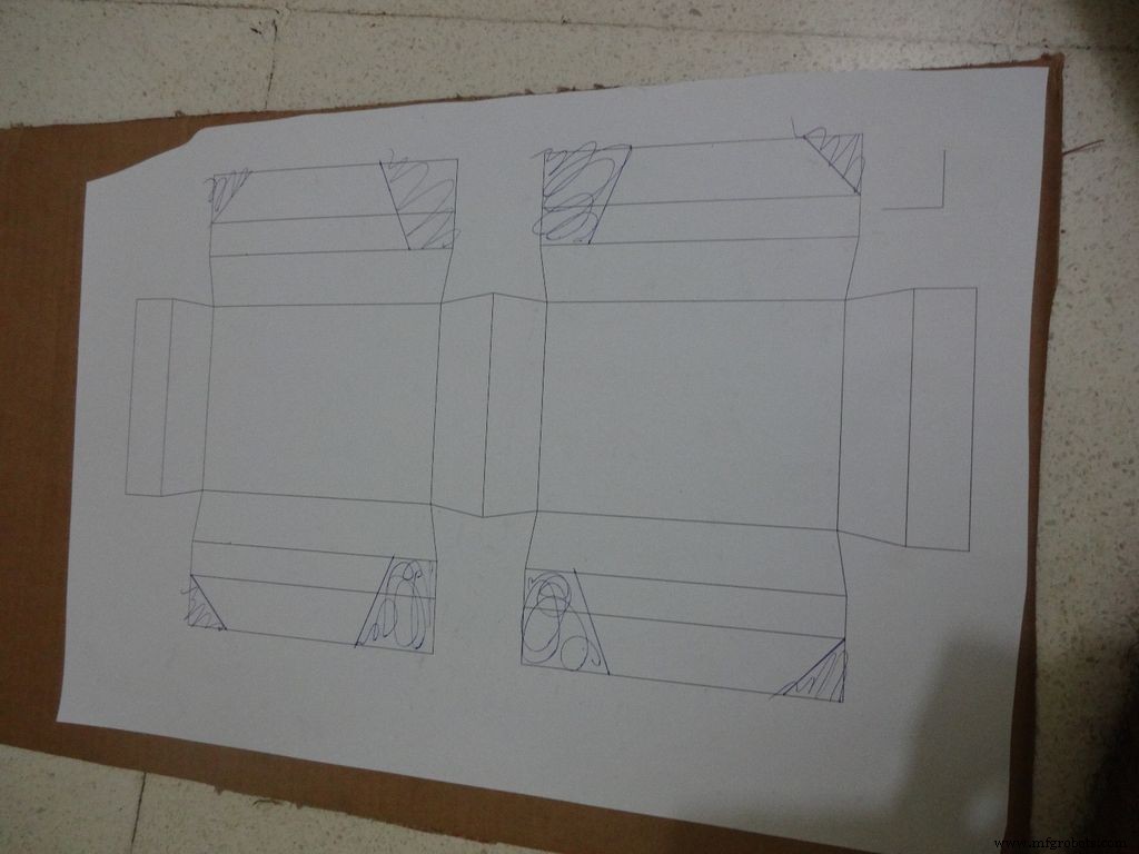
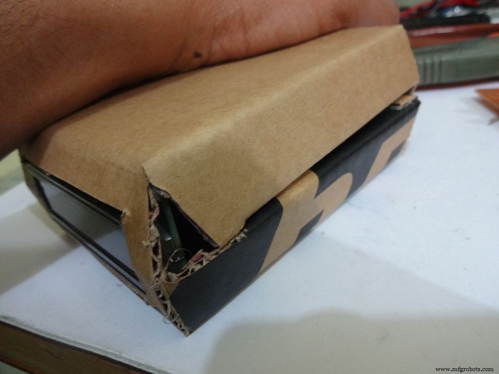
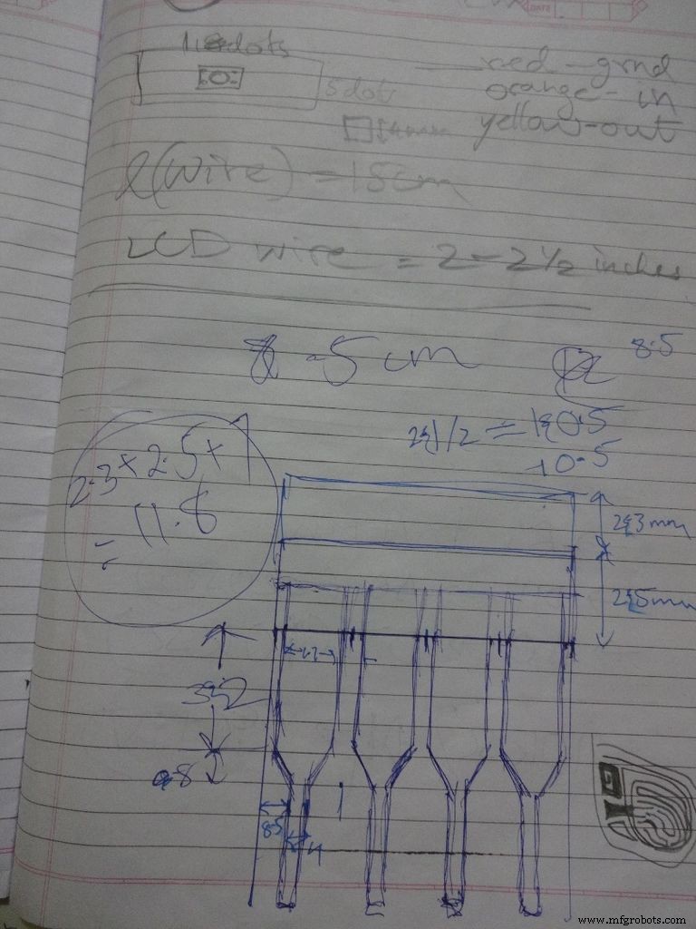
While testing the various circuits and when I had the rough idea of what I want to make, I decided to go with the IC design. I measured actual ICs, took ratios of their lengths, got the angle with some trignometry to be around 80 degrees. Then I decided the inner box length and breadth and built upon it(shown in image). Once the layout was planned, I initially started to draw it accurately on a large size paper. After a bit of a struggle of drawing accurate lines, I realised that this kind of work should be done on a computer! So I learnt CAD basics and succesfully made the layout on it. :) But this layout didnt work out and I had to redo the entire cutting and making of the case.(See images)
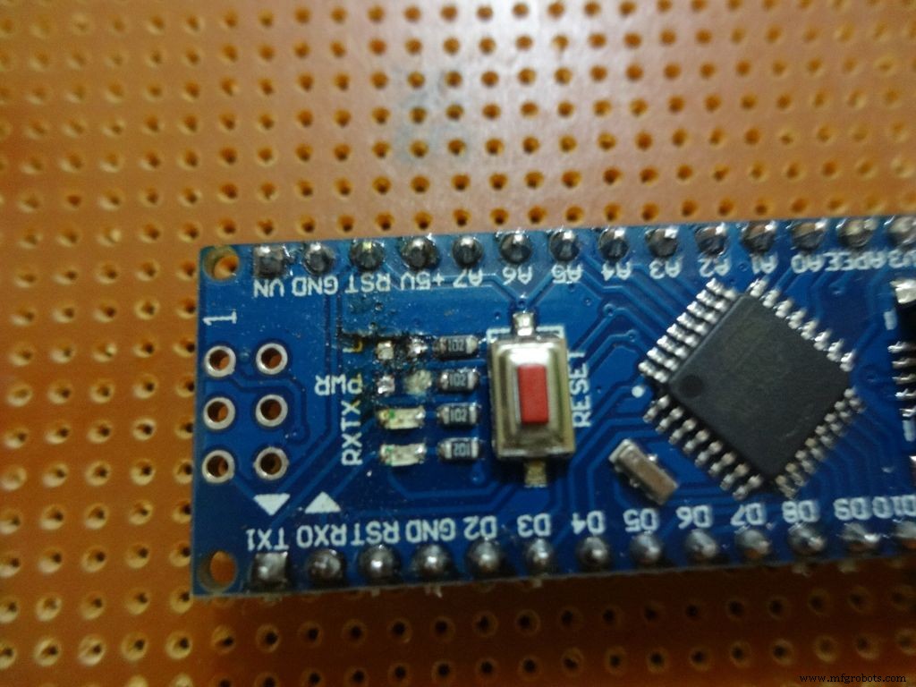
While removing the LEDs on the Arduino Nano I used excess pressure to remove a stubborn LED, and ended up removing a PCB pad. Always desolder without forcing/applying pressure on the joints, the pads are delicate and easily come off if you dont stay calm.
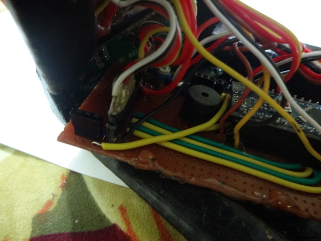
When all the solder joints were made and project was about to get finished, in excitement and eagerness, I glued the PCB inside the case before adding the battery case. Had to re-melt the hot glue with a soldering iron (carefully not to melt any wire insulation) and remove the PCB out to solder the battery case wires in. The soldering iron can be cleaned afterwards.
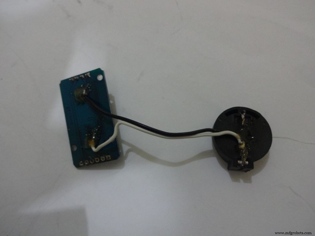
The RTC module battery was coming in way of the batteries while closing and so I separated the battery holder(Warning:desolder only with the battery removed) and added extension wires so that the battery can be placed at the sides where there is space.
All the Layout PDFs, CAD Files and the Main code can be downloaded here:Google Drive
Código
- Fragmento de código n. ° 1
- Fragmento de código n. ° 2
- Fragmento de código n. ° 3
- Fragmento de código n. ° 4
Fragmento de código n. ° 1 Texto sin formato
//Analog pin used to find resistanceint Apin=7;//values of r1 to r5float r1=1000;float r2=4700;float r3=10000;float r4=47000;float r5=100000;//pins of r1 to r5int r1_pin=2;int r2_pin=3;int r3_pin=4;int r4_pin=5;int r5_pin=6;float reading=0; //read from analog pin and store herefloat R=0; //calculate unknown and store hereString finalR; //final value to be displayed along with unitsint caseno; //for debugging, stores the case number // we divide the entire range into cases and assign each a number, // total 5 cases // case1 :less than 2850 // case2 :2850 to 7350 // case3 :7350 to 28500 // case4 :28500 to 73500 // case5 :more than 73500#include// needed for converting float to string, //has the String(float,n) function. Explained below.void setup() { Serial.begin(9600);}void loop() { //first we find unknown resistance using 1kOhm resistor //Therefore, disable R2, R3, R4 and R5 digitalWrite(r2_pin, LOW); //turn each pin to LOW before setting it as INPUT pinMode(r2_pin, INPUT); // turning it to INPUT when its HIGH enables the // internal pullup resistor digitalWrite(r3_pin, LOW); pinMode(r3_pin, INPUT); digitalWrite(r4_pin, LOW); pinMode(r4_pin, INPUT); digitalWrite(r5_pin, LOW); pinMode(r5_pin, INPUT); pinMode(r1_pin, OUTPUT); digitalWrite(r1_pin, HIGH); //read and calculate resistance reading=analogRead(Apin); R=(reading*r1)/(1023-reading); // if value <2850, finalR =value(using 1kOhm) if(R<2850){ caseno=1; if(R<1000){ //if value less than 1000 use "Ohm" not "kOhm" finalR =String(R,2) + "Ohm"; //String(float,n) Converting float to string //with n digits after decimal // attach "Ohm" after value to the string, //'+' joins two strings here } else{ //use "kOhm R=R/1000; finalR =String(R,2) + "kOhm"; } } //if value between 2850 and 7350 , use value obtained by 4.7kOhm else if(R>=2850 &&R<7350){ caseno=2; digitalWrite(r1_pin, LOW); //Enable only 4.7kOhm pinMode(r1_pin, INPUT); digitalWrite(r3_pin, LOW); pinMode(r3_pin, INPUT); digitalWrite(r4_pin, LOW); pinMode(r4_pin, INPUT); digitalWrite(r5_pin, LOW); pinMode(r5_pin, INPUT); pinMode(r2_pin, OUTPUT); digitalWrite(r2_pin, HIGH); reading=analogRead(Apin); R=(reading*r2)/(1023-reading)/1000; finalR =String(R,2) + "kOhm"; } //if value between 7350 and 28500, use value obtained by 10kOhm else if(R>=7350 &&R<28500){ caseno=3; digitalWrite(r1_pin, LOW); pinMode(r1_pin, INPUT); digitalWrite(r2_pin, LOW); pinMode(r2_pin, INPUT); digitalWrite(r4_pin, LOW); pinMode(r4_pin, INPUT); digitalWrite(r5_pin, LOW); pinMode(r5 _pin, INPUT); pinMode(r3_pin, OUTPUT); digitalWrite(r3_pin, HIGH); reading=analogRead(Apin); R=(reading*r3)/(1023-reading)/1000; finalR=String(R,2) + "kOhm"; } //if value between 28500 and 73500, use value obtained by 47kOhm else if(R>=28500 &&R<73500){ caseno=4; digitalWrite(r1_pin, LOW); pinMode(r1_pin, INPUT); digitalWrite(r2_pin, LOW); pinMode(r2_pin, INPUT); digitalWrite(r3_pin, LOW); pinMode(r3_pin, INPUT); digitalWrite(r5_pin, LOW); pinMode(r5_pin, INPUT); pinMode(r4_pin, OUTPUT); digitalWrite(r4_pin, HIGH); reading=analogRead(Apin); R=(reading*r4)/(1023-reading)/1000; finalR =String(R,2) + "kOhm"; } //if value more than 73500, use value obtained by 100kOhm else if(R>=73500){ caseno=5; digitalWrite(r1_pin, LOW); pinMode(r1_pin, INPUT); digitalWrite(r2_pin, LOW); pinMode(r2_pin, INPUT); digitalWrite(r3_pin, LOW); pinMode(r3_pin, INPUT); digitalWrite(r4_pin, LOW); pinMode(r4_pin, INPUT); pinMode(r5_pin, OUTPUT); digitalWrite(r5_pin, HIGH); reading=analogRead(Apin); R=(reading*r5)/(1023-reading)/1000; finalR =String(R,2) + "kOhm"; } Serial.println(finalR); //printing the final string with units Serial.println(" "); retraso (1000); }
Fragmento de código n. ° 2 Texto sin formato
/* RCTiming_capacitance_meter * code concept taken from Paul Badger 2008 * * The capacitor's voltage at one time constant is defined as * 63.2% of the charging voltage. * i.e, A Capacitor is filled to 63.2% of its total capacity in * 1 Time Constant */ int analogPin=0; // analog pin for measuring capacitor voltage int chargePin=7; // pin to charge the capacitor - connected to // one end of the charging resistor int dischargePin=12; // pin to discharge the capacitor, // same used for diode test(checkPin1) float resistorValue=10000.0; // We use 10kOhm resistor unsigned long startTime; unsigned long elapsedTime; float microFarads; // floating point variable to preserve precision float nanoFarads;void setup(){ pinMode(chargePin, OUTPUT); // set chargePin to output digitalWrite(chargePin, LOW); Serial.begin (9600); // initialize serial transmission for debugging}void loop(){ digitalWrite(chargePin, HIGH); // set chargePin HIGH and capacitor charging startTime =millis(); while(analogRead(analogPin) <648){ // just wait and do nothing till 648 // 647 is 63.2% of 1023, // which corresponds to full-scale voltage } elapsedTime=millis() - startTime; // convert milliseconds to seconds ( 10^-3 ) // and Farads to microFarads ( 10^6 ), net 10^3 (1000) microFarads =((float)elapsedTime / resistorValue) * 1000; // (float) converts "unsigned long" elapsed time to float Serial.print(elapsedTime); // print the value to serial port Serial.print(" mS "); // print units if (microFarads> 1){ Serial.print((long)microFarads); // print the value to serial port Serial.println(" microFarads"); // print units } else { // if value is smaller than one microFarad, convert to nanoFarads (10^-9 Farad). nanoFarads =microFarads * 1000.0; // multiply by 1000 to convert to nanoFarads (10^-9 Farads) Serial.print((long)nanoFarads); // print the value to serial port Serial.println(" nanoFarads"); // print units } /* dicharge the capacitor */ digitalWrite(chargePin, LOW); // set charge pin to LOW pinMode(dischargePin, OUTPUT); // set discharge pin to output digitalWrite(dischargePin, LOW); // set discharge pin LOW while(analogRead(analogPin)> 0){ // wait until capacitor is completely discharged } pinMode(dischargePin, INPUT); // set discharge pin back to input} Fragmento de código n. ° 3 Texto sin formato
String state ="null"; //prints "null" for reverse bias or nothing connectedint checkPin1 =12;int checkPin2 =6;void setup() { Serial.begin(9600);}void loop() {pinMode(checkPin1, OUTPUT); digitalWrite(checkPin1, LOW); //pin 11 is set to low//analog read is normally pulled up by the 10k resistor, so null reading is 1023//In forward bias, the analog pin gets connected to checkPin1, which is LOW. So reading less than 1023//Practically a small current flows in reverse bias as well, so we take 700 to differentiate if(analogRead(checkPin2)<700){ state="forward"; } Serial.println(state); Serial.println(analogRead(checkPin2)); state ="null"; delay(500);} Fragmento de código n.º 4 Texto sin formato
// Date and time functions using a DS1307 RTC connected via I2C and Wire lib#include #include RTC_DS1307 rtc;//creating "rtc" object of RTC_DS1307, objects are used to access functions //more on objects and classes:https://www.youtube.com/watch?v=ABRP_5RYhqUchar daysOfTheWeek[7][12] ={"Sunday", "Monday", "Tuesday", "Wednesday", "Thursday", "Friday", "Saturday"};void setup () { Serial.begin(9600); rtc.begin(); // following line sets the RTC to the date &time this sketch was compiled // rtc.adjust(DateTime(F(__DATE__), F(__TIME__))); // This line sets the RTC with an explicit date &time, for example to set // January 21, 2014 at 3am you would call:// rtc.adjust(DateTime(2014, 1, 21, 3, 0, 0));}void loop () { DateTime now =rtc.now(); Serial.print(now.year()); Serial.print('/'); Serial.print(now.month()); Serial.print('/'); Serial.print(now.day()); Serial.print(" ("); Serial.print(daysOfTheWeek[now.dayOfTheWeek()]); Serial.print(") "); Serial.print(now.hour()); Serial.print(':'); Serial.print(now.minute()); Serial.print(':'); Serial.print(now.second()); Serial.println(); Serial.println(); delay(1000);} Github
https://github.com/adafruit/RTClibhttps://github.com/adafruit/RTClibEsquemas
Main_Schematic.fzzProceso de manufactura
- Alerta de sed Alarma de planta
- Reloj Word en italiano
- Solo tres pines para un teclado de 4x3
- Medidor de kWh Sigfox
- Monitor de temperatura Bluetooth
- Bloqueo controlado por gestos
- Adaptador MIDI USB
- Una entrada analógica aislada para Arduino
- Visualizador de espectro de audio RGB de 32 bandas
- Cable de salida de TV Arduino
- Mide tu tiempo de reacción


