


Arduino Robot Car Wireless Control utilizando HC-05 Bluetooth, NRF24L01 y módulos transceptores HC-12
En este tutorial aprenderemos a controlar de forma inalámbrica el coche robot Arduino que hicimos en el vídeo anterior. Le mostraré tres métodos diferentes de control inalámbrico, usando el módulo Bluetooth HC-05, el módulo transceptor NRF24L01 y el módulo inalámbrico de largo alcance HC-12, así como también usando un teléfono inteligente y una aplicación de Android hecha a medida. Puede ver el siguiente video o leer el tutorial escrito a continuación para obtener más detalles.
Ya tengo tutoriales de cómo conectar y utilizar cada uno de estos módulos con la placa Arduino, así que si necesitas más detalles siempre puedes consultarlos. Los enlaces a cada uno de ellos se pueden encontrar a continuación en el artículo.
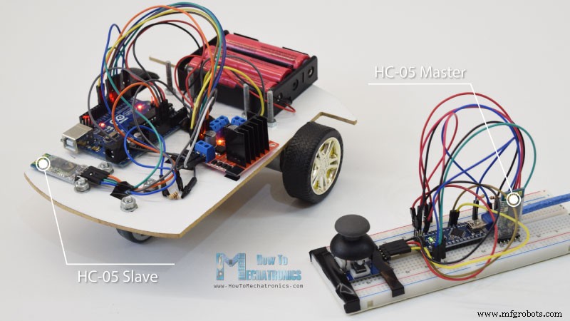
Comenzaremos con la comunicación Bluetooth, y para ello necesitamos dos módulos Bluetooth HC-05 que deben configurarse como dispositivos maestro y esclavo.
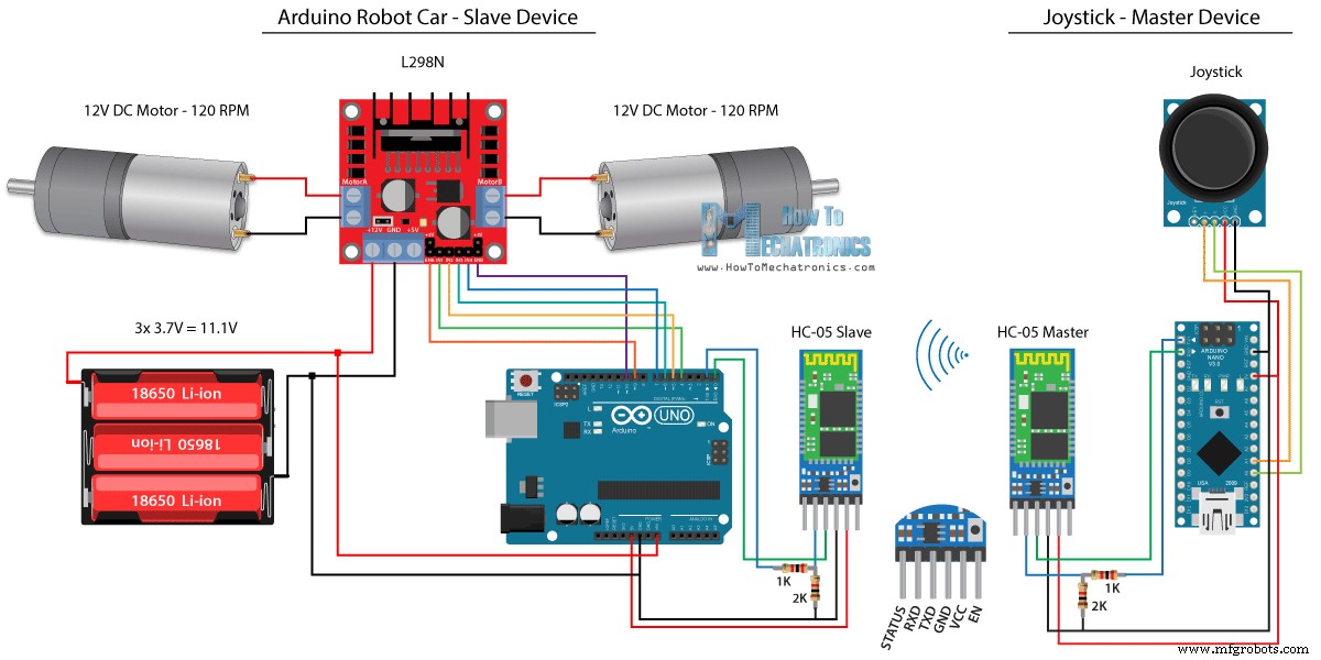
Podemos hacerlo fácilmente usando comandos AT, y configuré el joystick para que sea maestro y el automóvil robot Arduino para que sea esclavo. Aquí está el esquema del circuito completo para este ejemplo:
Puede obtener los componentes necesarios para este ejemplo en los siguientes enlaces:
Usaremos el mismo código del tutorial anterior, donde controlamos el auto robot Arduino directamente usando el joystick, y le haremos algunas modificaciones.
HC-05 Código maestro:
El código en el dispositivo maestro o el joystick es bastante simple. Solo necesitamos leer los valores X e Y del joystick, que en realidad regulan la velocidad de los motores, y enviarlos a través del puerto serie al dispositivo esclavo Bluetooth HC-05. Podemos notar aquí que los valores analógicos del joystick de 0 a 1023 se convierten en valores de 0 a 255 sumergiéndolos en 4.
Hacemos esto porque ese rango, de 0 a 255, se puede enviar, a través del dispositivo Bluetooth, como 1 byte, que es más fácil de aceptar en el otro lado, o en el automóvil robot Arduino.
Así que aquí, si el serial ha recibido los 2 bytes, los valores X e Y, usando la función Serial.read() leeremos ambos.
Ahora solo tenemos que volver a convertir los valores al rango de 0 a 1023, adecuado para el código de control de motor a continuación, que ya explicamos cómo funciona en el video anterior.
Solo una nota rápida:al cargar el código, debemos desconectar los pines RX y TX de la placa Arduino.
Código esclavo HC-05 completo:
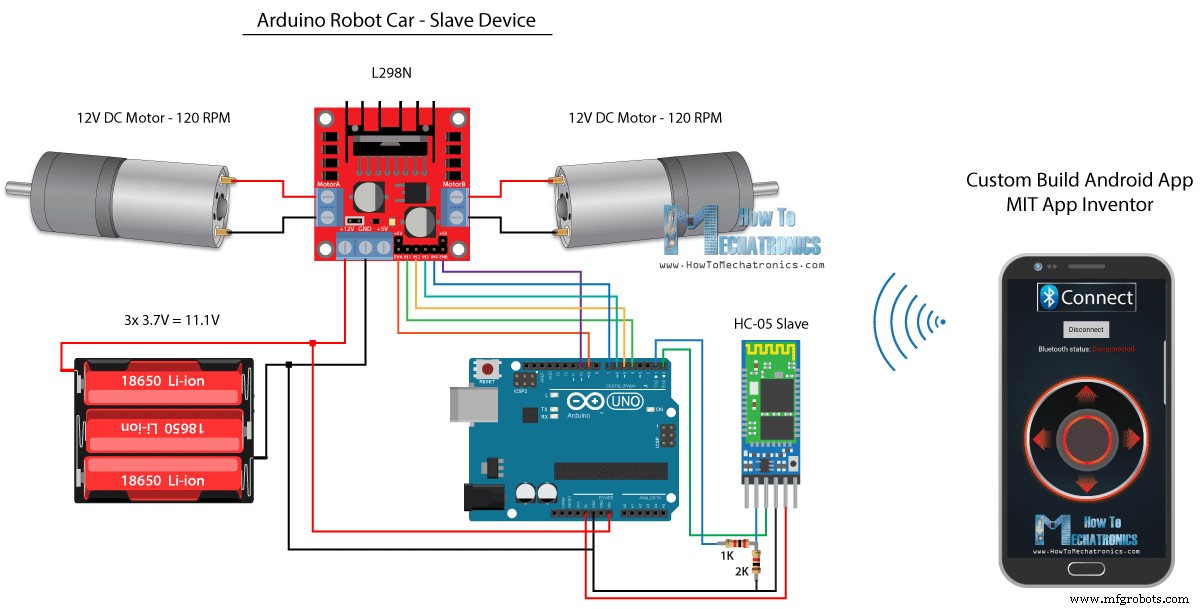
A continuación, veamos cómo podemos controlar nuestro automóvil robot Arduino usando una aplicación de Android personalizada. El esquema del circuito del coche robot es exactamente el mismo que el del ejemplo anterior, con el modo Bluetooth HC-05 configurado como dispositivo esclavo.
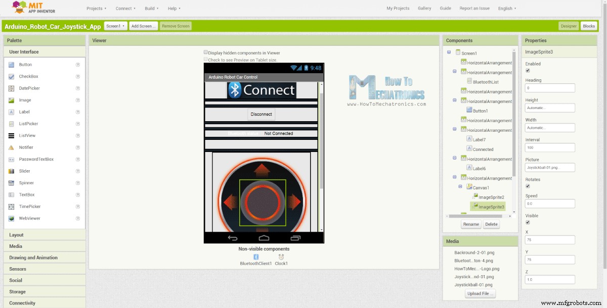
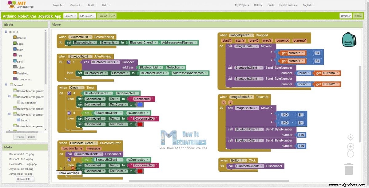
Por otro lado, usando la aplicación en línea MIT App Inventor crearemos nuestra propia aplicación para Android, y así es como se ve.
Básicamente, la aplicación simula un joystick, cuya apariencia está compuesta por dos imágenes o sprites de imágenes.
Si echamos un vistazo a los bloques de esta aplicación, podemos ver que cuando se arrastra el sprite del joystick, la imagen de la bola del joystick se mueve a la ubicación actual de nuestro dedo, y al mismo tiempo enviamos la X y la Y valores a través de Bluetooth al coche Arduino.
Estos valores son aceptados por Arduino de la misma forma que en el ejemplo anterior, utilizando la función Serial.read.
Lo que debemos hacer adicionalmente aquí es convertir los valores X e Y recibidos del teléfono inteligente en el rango de 0 a 1023, adecuado para el código de control del motor a continuación. Estos valores dependen del tamaño del lienzo, y los valores X e Y que obtenía de mi aplicación eran de 60 a 220, que usando la función map() los convertí fácilmente.
En los bloques de aplicaciones, también podemos ver que cuando se retoca el sprite de la imagen, la bola del joystick se mueve hacia el centro del lienzo y se envían los valores apropiados al automóvil para que deje de moverse. Puede encontrar y descargar esta aplicación en el artículo del sitio web, así como las dos imágenes del joystick para que pueda crear su propia aplicación o modificar esta aplicación.
Puede descargar la aplicación de Android a continuación, así como las dos imágenes para el joystick:
Código Arduino completo:
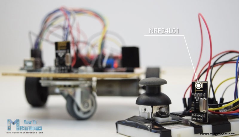
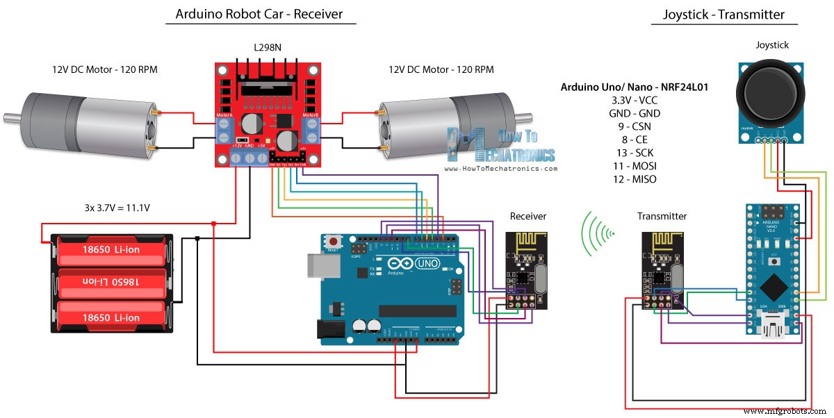
Ahora podemos pasar al siguiente método, el control inalámbrico del coche robot Arduino utilizando los módulos transceptores NRF24L01.
Aquí está el esquema del circuito. Podemos notar que estos módulos usan la comunicación SPI, por lo que, en comparación con el ejemplo anterior, moví los pines Habilitar A y Habilitar B del controlador L298N a los pines número 2 y 3 de la placa Arduino. Puede obtener el NRF24L01 módulo en el siguiente enlace de Amazon.
Para este ejemplo, necesitamos instalar la biblioteca RF24. De forma similar al ejemplo anterior, después de definir algunos pines y configurar el módulo como transmisor, leemos los valores X e Y del joystick y los enviamos al otro módulo NRF24L01 en el coche robot Arduino.
Primero, podemos notar que las lecturas analógicas son cadenas, que al usar la función string.toCharArray() se colocan en una matriz de caracteres. Luego, usando la función radio.write(), enviamos esa matriz de datos de caracteres al otro módulo.
Código del transmisor:
Por otro lado. en el coche robot Arduino, después de definir el módulo como receptor, aceptamos datos usando la función radio.read(). Luego, usando la función atoi(), convertimos los datos recibidos, o los valores X e Y del joystick, en valores enteros, que son adecuados para el código de control del motor a continuación.
Es así de simple, pero por supuesto, como ya dije, si necesita más detalles sobre cómo conectar y configurar los módulos, siempre puede consultar mi tutorial particular.
Código del receptor:
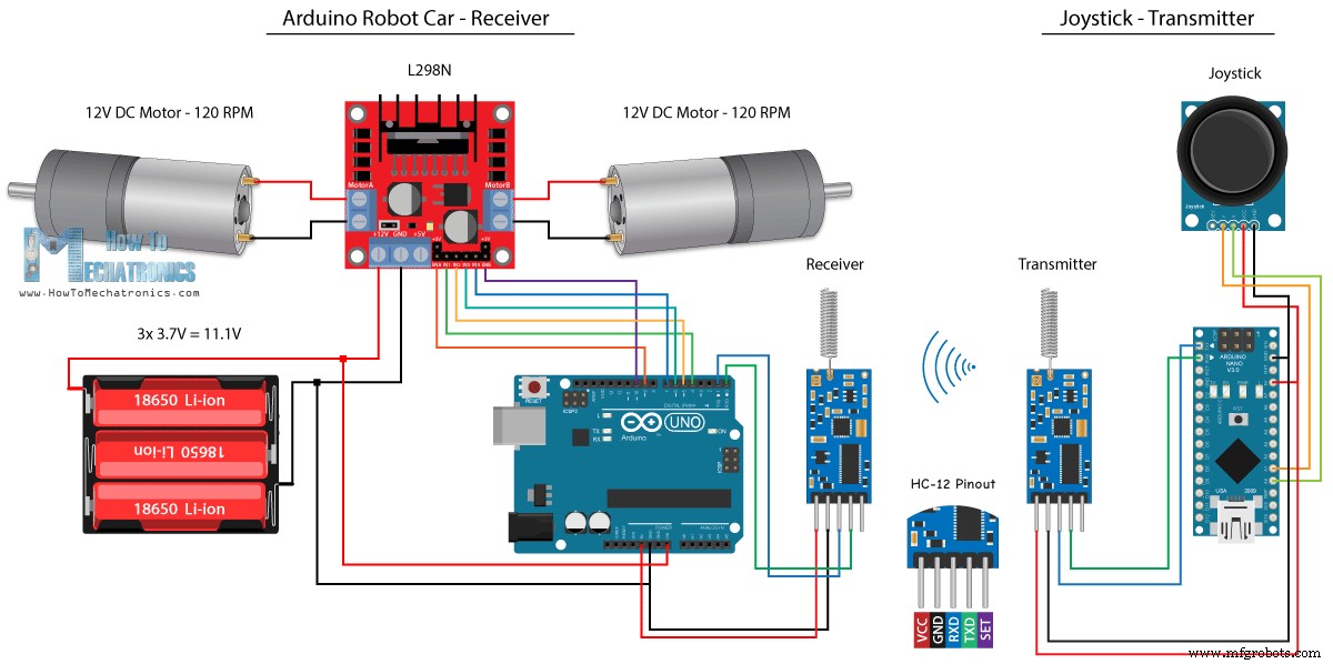
Para el último método de control inalámbrico del coche robot Arduino, utilizaremos los módulos transceptores de largo alcance HC-12. Estos módulos pueden comunicarse entre sí con distancias de hasta 1,8 km.
El esquema del circuito para este ejemplo es casi el mismo que el de los módulos Bluetooth HC-05, ya que utilizan el mismo método para comunicarse con Arduino, a través del puerto serie.
Puede obtener el módulo transceptor HC-12 en el siguiente enlace de Amazon.
El código del Joystick es exactamente el mismo que el de la comunicación Bluetooth. Simplemente leemos los valores analógicos del joystick y los enviamos al otro módulo usando la función Serial.write().
Código del transmisor:
Por otro lado, con el ciclo while() esperamos hasta que lleguen los datos, luego los leemos usando la función Serial.read() y los volvemos a convertir al rango de 0 a 1023, adecuado para el código de control de motor a continuación.
Código del receptor:
Así que eso es prácticamente todo para este tutorial. No dude en hacer cualquier pregunta en la sección de comentarios a continuación.Arduino Robot Car Control usando el módulo Bluetooth HC-05
Código fuente
/*
   Arduino Robot Car Wireless Control using the HC-05 Bluetooth

                == MASTER DEVICE - Joystick ==

   by Dejan Nedelkovski, www.HowToMechatronics.com
*/

int xAxis, yAxis;

void setup() {
  Serial.begin(38400); // Default communication rate of the Bluetooth module
}

void loop() {
  xAxis = analogRead(A0); // Read Joysticks X-axis
  yAxis = analogRead(A1); // Read Joysticks Y-axis

  // Send the values via the serial port to the slave HC-05 Bluetooth device
  Serial.write(xAxis/4); // Dividing by 4 for converting from 0 - 1023 to 0 - 256, (1 byte) range
  Serial.write(yAxis/4);
  delay(20);
}Code language: Arduino (arduino)// Code from the Arduino Robot Car
// Read the incoming data from the Joystick, or the master Bluetooth device
while (Serial.available() >= 2) {
x = Serial.read();
delay(10);
y = Serial.read();
}Code language: Arduino (arduino)// Code from the Arduino Robot Car
// Convert back the 0 - 255 range to 0 - 1023, suitable for motor control code below
xAxis = x*4;
yAxis = y*4;Code language: Arduino (arduino)/*
Arduino Robot Car Wireless Control using the HC-05 Bluetooth
== SLAVE DEVICE - Arduino robot car ==
by Dejan Nedelkovski, www.HowToMechatronics.com
*/
#define enA 9
#define in1 4
#define in2 5
#define enB 10
#define in3 6
#define in4 7
int xAxis, yAxis;
unsigned int x = 0;
unsigned int y = 0;
int motorSpeedA = 0;
int motorSpeedB = 0;
void setup() {
pinMode(enA, OUTPUT);
pinMode(enB, OUTPUT);
pinMode(in1, OUTPUT);
pinMode(in2, OUTPUT);
pinMode(in3, OUTPUT);
pinMode(in4, OUTPUT);
Serial.begin(38400); // Default communication rate of the Bluetooth module
}
void loop() {
// Default value - no movement when the Joystick stays in the center
x = 510 / 4;
y = 510 / 4;
// Read the incoming data from the Joystick, or the master Bluetooth device
while (Serial.available() >= 2) {
x = Serial.read();
delay(10);
y = Serial.read();
}
delay(10);
// Convert back the 0 - 255 range to 0 - 1023, suitable for motor control code below
xAxis = x*4;
yAxis = y*4;
// Y-axis used for forward and backward control
if (yAxis < 470) {
// Set Motor A backward
digitalWrite(in1, HIGH);
digitalWrite(in2, LOW);
// Set Motor B backward
digitalWrite(in3, HIGH);
digitalWrite(in4, LOW);
// Convert the declining Y-axis readings for going backward from 470 to 0 into 0 to 255 value for the PWM signal for increasing the motor speed
motorSpeedA = map(yAxis, 470, 0, 0, 255);
motorSpeedB = map(yAxis, 470, 0, 0, 255);
}
else if (yAxis > 550) {
// Set Motor A forward
digitalWrite(in1, LOW);
digitalWrite(in2, HIGH);
// Set Motor B forward
digitalWrite(in3, LOW);
digitalWrite(in4, HIGH);
// Convert the increasing Y-axis readings for going forward from 550 to 1023 into 0 to 255 value for the PWM signal for increasing the motor speed
motorSpeedA = map(yAxis, 550, 1023, 0, 255);
motorSpeedB = map(yAxis, 550, 1023, 0, 255);
}
// If joystick stays in middle the motors are not moving
else {
motorSpeedA = 0;
motorSpeedB = 0;
}
// X-axis used for left and right control
if (xAxis < 470) {
// Convert the declining X-axis readings from 470 to 0 into increasing 0 to 255 value
int xMapped = map(xAxis, 470, 0, 0, 255);
// Move to left - decrease left motor speed, increase right motor speed
motorSpeedA = motorSpeedA - xMapped;
motorSpeedB = motorSpeedB + xMapped;
// Confine the range from 0 to 255
if (motorSpeedA < 0) {
motorSpeedA = 0;
}
if (motorSpeedB > 255) {
motorSpeedB = 255;
}
}
if (xAxis > 550) {
// Convert the increasing X-axis readings from 550 to 1023 into 0 to 255 value
int xMapped = map(xAxis, 550, 1023, 0, 255);
// Move right - decrease right motor speed, increase left motor speed
motorSpeedA = motorSpeedA + xMapped;
motorSpeedB = motorSpeedB - xMapped;
// Confine the range from 0 to 255
if (motorSpeedA > 255) {
motorSpeedA = 255;
}
if (motorSpeedB < 0) {
motorSpeedB = 0;
}
}
// Prevent buzzing at low speeds (Adjust according to your motors. My motors couldn't start moving if PWM value was below value of 70)
if (motorSpeedA < 70) {
motorSpeedA = 0;
}
if (motorSpeedB < 70) {
motorSpeedB = 0;
}
analogWrite(enA, motorSpeedA); // Send PWM signal to motor A
analogWrite(enB, motorSpeedB); // Send PWM signal to motor B
}Code language: Arduino (arduino)Arduino Robot Car Control usando un teléfono inteligente y una aplicación de Android personalizada
// Read the incoming data from the Smartphone Android App
  while (Serial.available() >= 2) {
    x = Serial.read();
    delay(10);
    y = Serial.read();
}Code language: Arduino (arduino)// Makes sure we receive corrent values
if (x > 60 & x < 220) {
xAxis = map(x, 220, 60, 1023, 0); // Convert the smartphone X and Y values to 0 - 1023 range, suitable motor for the motor control code below
}
if (y > 60 & y < 220) {
yAxis = map(y, 220, 60, 0, 1023);
}Code language: Arduino (arduino)
Arduino_Robot_Car_Joystick_App.apk
1 archivo(s) 1.62MB Descargar Arduino_Robot_Car_Joystick_App_aia_file
1 archivo(s) 171.20 KB Descargar Imágenes de la aplicación Joystick
1 archivo(s) 44.36 KB Descargar /*
Arduino Robot Car Wireless Control using the HC-05 Bluetooth and custom-build Android app
== SLAVE DEVICE - Arduino robot car ==
by Dejan Nedelkovski, www.HowToMechatronics.com
*/
#define enA 9
#define in1 4
#define in2 5
#define enB 10
#define in3 6
#define in4 7
int xAxis, yAxis;
int x = 0;
int y = 0;
int motorSpeedA = 0;
int motorSpeedB = 0;
void setup() {
pinMode(enA, OUTPUT);
pinMode(enB, OUTPUT);
pinMode(in1, OUTPUT);
pinMode(in2, OUTPUT);
pinMode(in3, OUTPUT);
pinMode(in4, OUTPUT);
Serial.begin(38400); // Default communication rate of the Bluetooth module
}
void loop() {
// Default value - no movement when the Joystick stays in the center
xAxis = 510;
yAxis = 510;
// Read the incoming data from the Smartphone Android App
while (Serial.available() >= 2) {
x = Serial.read();
delay(10);
y = Serial.read();
}
delay(10);
// Makes sure we receive corrent values
if (x > 60 & x < 220) {
xAxis = map(x, 220, 60, 1023, 0); // Convert the smartphone X and Y values to 0 - 1023 range, suitable motor for the motor control code below
}
if (y > 60 & y < 220) {
yAxis = map(y, 220, 60, 0, 1023);
}
// Y-axis used for forward and backward control
if (yAxis < 470) {
// Set Motor A backward
digitalWrite(in1, HIGH);
digitalWrite(in2, LOW);
// Set Motor B backward
digitalWrite(in3, HIGH);
digitalWrite(in4, LOW);
// Convert the declining Y-axis readings for going backward from 470 to 0 into 0 to 255 value for the PWM signal for increasing the motor speed
motorSpeedA = map(yAxis, 470, 0, 0, 255);
motorSpeedB = map(yAxis, 470, 0, 0, 255);
}
else if (yAxis > 550) {
// Set Motor A forward
digitalWrite(in1, LOW);
digitalWrite(in2, HIGH);
// Set Motor B forward
digitalWrite(in3, LOW);
digitalWrite(in4, HIGH);
// Convert the increasing Y-axis readings for going forward from 550 to 1023 into 0 to 255 value for the PWM signal for increasing the motor speed
motorSpeedA = map(yAxis, 550, 1023, 0, 255);
motorSpeedB = map(yAxis, 550, 1023, 0, 255);
}
// If joystick stays in middle the motors are not moving
else {
motorSpeedA = 0;
motorSpeedB = 0;
}
// X-axis used for left and right control
if (xAxis < 470) {
// Convert the declining X-axis readings from 470 to 0 into increasing 0 to 255 value
int xMapped = map(xAxis, 470, 0, 0, 255);
// Move to left - decrease left motor speed, increase right motor speed
motorSpeedA = motorSpeedA - xMapped;
motorSpeedB = motorSpeedB + xMapped;
// Confine the range from 0 to 255
if (motorSpeedA < 0) {
motorSpeedA = 0;
}
if (motorSpeedB > 255) {
motorSpeedB = 255;
}
}
if (xAxis > 550) {
// Convert the increasing X-axis readings from 550 to 1023 into 0 to 255 value
int xMapped = map(xAxis, 550, 1023, 0, 255);
// Move right - decrease right motor speed, increase left motor speed
motorSpeedA = motorSpeedA + xMapped;
motorSpeedB = motorSpeedB - xMapped;
// Confine the range from 0 to 255
if (motorSpeedA > 255) {
motorSpeedA = 255;
}
if (motorSpeedB < 0) {
motorSpeedB = 0;
}
}
// Prevent buzzing at low speeds (Adjust according to your motors. My motors couldn't start moving if PWM value was below value of 70)
if (motorSpeedA < 70) {
motorSpeedA = 0;
}
if (motorSpeedB < 70) {
motorSpeedB = 0;
}
analogWrite(enA, motorSpeedA); // Send PWM signal to motor A
analogWrite(enB, motorSpeedB); // Send PWM signal to motor B
}Code language: Arduino (arduino)Control inalámbrico de Arduino Robot Car mediante el módulo transceptor NRF24L01
Código fuente
/*
   Arduino Robot Car Wireless Control using the NRF24L01 Transceiver module

             == Transmitter - Joystick ==

   by Dejan Nedelkovski, www.HowToMechatronics.com

   Library: TMRh20/RF24, https://github.com/tmrh20/RF24/
*/

#include <SPI.h>
#include <nRF24L01.h>
#include <RF24.h>

RF24 radio(8, 9); // CE, CSN
const byte address[6] = "00001";

char xyData[32] = "";
String xAxis, yAxis;

void setup() {
  Serial.begin(9600);
  radio.begin();
  radio.openWritingPipe(address);
  radio.setPALevel(RF24_PA_MIN);
  radio.stopListening();
}

void loop() {

  xAxis = analogRead(A0); // Read Joysticks X-axis
  yAxis = analogRead(A1); // Read Joysticks Y-axis
  // X value
  xAxis.toCharArray(xyData, 5); // Put the String (X Value) into a character array
  radio.write(&xyData, sizeof(xyData)); // Send the array data (X value) to the other NRF24L01 modile
  // Y value
  yAxis.toCharArray(xyData, 5);
  radio.write(&xyData, sizeof(xyData));
  delay(20);
}Code language: Arduino (arduino)// Code from the Arduino Robot Car - NRF24L01 example
if (radio.available()) { // If the NRF240L01 module received data
radio.read(&receivedData, sizeof(receivedData)); // Read the data and put it into character array
xAxis = atoi(&receivedData[0]); // Convert the data from the character array (received X value) into integer
delay(10);
radio.read(&receivedData, sizeof(receivedData));
yAxis = atoi(&receivedData[0]);
delay(10);
}Code language: Arduino (arduino)/*
Arduino Robot Car Wireless Control using the NRF24L01 Transceiver module
== Receiver - Arduino robot car ==
by Dejan Nedelkovski, www.HowToMechatronics.com
Library: TMRh20/RF24, https://github.com/tmrh20/RF24/
*/
#include <SPI.h>
#include <nRF24L01.h>
#include <RF24.h>
#define enA 2 // Note: Pin 9 in previous video ( pin 10 is used for the SPI communication of the NRF24L01)
#define in1 4
#define in2 5
#define enB 3 // Note: Pin 10 in previous video
#define in3 6
#define in4 7
RF24 radio(8, 9); // CE, CSN
const byte address[6] = "00001";
char receivedData[32] = "";
int xAxis, yAxis;
int motorSpeedA = 0;
int motorSpeedB = 0;
void setup() {
pinMode(enA, OUTPUT);
pinMode(enB, OUTPUT);
pinMode(in1, OUTPUT);
pinMode(in2, OUTPUT);
pinMode(in3, OUTPUT);
pinMode(in4, OUTPUT);
Serial.begin(9600);
radio.begin();
radio.openReadingPipe(0, address);
radio.setPALevel(RF24_PA_MIN);
radio.startListening();
}
void loop() {
if (radio.available()) { // If the NRF240L01 module received data
radio.read(&receivedData, sizeof(receivedData)); // Read the data and put it into character array
xAxis = atoi(&receivedData[0]); // Convert the data from the character array (received X value) into integer
delay(10);
radio.read(&receivedData, sizeof(receivedData));
yAxis = atoi(&receivedData[0]);
delay(10);
}
// Y-axis used for forward and backward control
if (yAxis < 470) {
// Set Motor A backward
digitalWrite(in1, HIGH);
digitalWrite(in2, LOW);
// Set Motor B backward
digitalWrite(in3, HIGH);
digitalWrite(in4, LOW);
// Convert the declining Y-axis readings for going backward from 470 to 0 into 0 to 255 value for the PWM signal for increasing the motor speed
motorSpeedA = map(yAxis, 470, 0, 0, 255);
motorSpeedB = map(yAxis, 470, 0, 0, 255);
}
else if (yAxis > 550) {
// Set Motor A forward
digitalWrite(in1, LOW);
digitalWrite(in2, HIGH);
// Set Motor B forward
digitalWrite(in3, LOW);
digitalWrite(in4, HIGH);
// Convert the increasing Y-axis readings for going forward from 550 to 1023 into 0 to 255 value for the PWM signal for increasing the motor speed
motorSpeedA = map(yAxis, 550, 1023, 0, 255);
motorSpeedB = map(yAxis, 550, 1023, 0, 255);
}
// If joystick stays in middle the motors are not moving
else {
motorSpeedA = 0;
motorSpeedB = 0;
}
// X-axis used for left and right control
if (xAxis < 470) {
// Convert the declining X-axis readings from 470 to 0 into increasing 0 to 255 value
int xMapped = map(xAxis, 470, 0, 0, 255);
// Move to left - decrease left motor speed, increase right motor speed
motorSpeedA = motorSpeedA - xMapped;
motorSpeedB = motorSpeedB + xMapped;
// Confine the range from 0 to 255
if (motorSpeedA < 0) {
motorSpeedA = 0;
}
if (motorSpeedB > 255) {
motorSpeedB = 255;
}
}
if (xAxis > 550) {
// Convert the increasing X-axis readings from 550 to 1023 into 0 to 255 value
int xMapped = map(xAxis, 550, 1023, 0, 255);
// Move right - decrease right motor speed, increase left motor speed
motorSpeedA = motorSpeedA + xMapped;
motorSpeedB = motorSpeedB - xMapped;
// Confine the range from 0 to 255
if (motorSpeedA > 255) {
motorSpeedA = 255;
}
if (motorSpeedB < 0) {
motorSpeedB = 0;
}
}
// Prevent buzzing at low speeds (Adjust according to your motors. My motors couldn't start moving if PWM value was below value of 70)
if (motorSpeedA < 70) {
motorSpeedA = 0;
}
if (motorSpeedB < 70) {
motorSpeedB = 0;
}
analogWrite(enA, motorSpeedA); // Send PWM signal to motor A
analogWrite(enB, motorSpeedB); // Send PWM signal to motor B
}Code language: Arduino (arduino)Control inalámbrico de Arduino Robot Car usando el transceptor de largo alcance HC-12
Código fuente
/*
   Arduino Robot Car Wireless Control using the HC-12 long range wireless module

                == Transmitter - Joystick ==

   by Dejan Nedelkovski, www.HowToMechatronics.com
*/

int xAxis, yAxis;

void setup() {
  Serial.begin(9600); // Default communication rate of the Bluetooth module
}

void loop() {
  xAxis = analogRead(A0); // Read Joysticks X-axis
  yAxis = analogRead(A1); // Read Joysticks Y-axis

  // Send the values via the serial port to the slave HC-05 Bluetooth device
  Serial.write(xAxis/4); // Dividing by 4 for converting from 0 - 1023 to 0 - 256, (1 byte) range
  Serial.write(yAxis/4);
  delay(20);
}Code language: Arduino (arduino)/*
Arduino Robot Car Wireless Control using the HC-12 long range wireless module
== Receiver - Arduino robot car ==
by Dejan Nedelkovski, www.HowToMechatronics.com
*/
#define enA 9
#define in1 4
#define in2 5
#define enB 10
#define in3 6
#define in4 7
int xAxis, yAxis;
int x = 0;
int y = 0;
int motorSpeedA = 0;
int motorSpeedB = 0;
void setup() {
pinMode(enA, OUTPUT);
pinMode(enB, OUTPUT);
pinMode(in1, OUTPUT);
pinMode(in2, OUTPUT);
pinMode(in3, OUTPUT);
pinMode(in4, OUTPUT);
Serial.begin(9600); // Default communication rate of the Bluetooth module
}
void loop() {
// Default value - no movement when the Joystick stays in the center
xAxis = 510;
yAxis = 510;
// Read the incoming data from the
while (Serial.available() == 0) {}
x = Serial.read();
delay(10);
y = Serial.read();
delay(10);
// Convert back the 0 - 255 range to 0 - 1023, suitable for motor control code below
xAxis = x * 4;
yAxis = y * 4;
// Y-axis used for forward and backward control
if (yAxis < 470) {
// Set Motor A backward
digitalWrite(in1, HIGH);
digitalWrite(in2, LOW);
// Set Motor B backward
digitalWrite(in3, HIGH);
digitalWrite(in4, LOW);
// Convert the declining Y-axis readings for going backward from 470 to 0 into 0 to 255 value for the PWM signal for increasing the motor speed
motorSpeedA = map(yAxis, 470, 0, 0, 255);
motorSpeedB = map(yAxis, 470, 0, 0, 255);
}
else if (yAxis > 550) {
// Set Motor A forward
digitalWrite(in1, LOW);
digitalWrite(in2, HIGH);
// Set Motor B forward
digitalWrite(in3, LOW);
digitalWrite(in4, HIGH);
// Convert the increasing Y-axis readings for going forward from 550 to 1023 into 0 to 255 value for the PWM signal for increasing the motor speed
motorSpeedA = map(yAxis, 550, 1023, 0, 255);
motorSpeedB = map(yAxis, 550, 1023, 0, 255);
}
// If joystick stays in middle the motors are not moving
else {
motorSpeedA = 0;
motorSpeedB = 0;
}
// X-axis used for left and right control
if (xAxis < 470) {
// Convert the declining X-axis readings from 470 to 0 into increasing 0 to 255 value
int xMapped = map(xAxis, 470, 0, 0, 255);
// Move to left - decrease left motor speed, increase right motor speed
motorSpeedA = motorSpeedA - xMapped;
motorSpeedB = motorSpeedB + xMapped;
// Confine the range from 0 to 255
if (motorSpeedA < 0) {
motorSpeedA = 0;
}
if (motorSpeedB > 255) {
motorSpeedB = 255;
}
}
if (xAxis > 550) {
// Convert the increasing X-axis readings from 550 to 1023 into 0 to 255 value
int xMapped = map(xAxis, 550, 1023, 0, 255);
// Move right - decrease right motor speed, increase left motor speed
motorSpeedA = motorSpeedA + xMapped;
motorSpeedB = motorSpeedB - xMapped;
// Confine the range from 0 to 255
if (motorSpeedA > 255) {
motorSpeedA = 255;
}
if (motorSpeedB < 0) {
motorSpeedB = 0;
}
}
// Prevent buzzing at low speeds (Adjust according to your motors. My motors couldn't start moving if PWM value was below value of 70)
if (motorSpeedA < 70) {
motorSpeedA = 0;
}
if (motorSpeedB < 70) {
motorSpeedB = 0;
}
analogWrite(enA, motorSpeedA); // Send PWM signal to motor A
analogWrite(enB, motorSpeedB); // Send PWM signal to motor B
}Code language: Arduino (arduino)
Proceso de manufactura
- Robot Raspberry Pi controlado por Bluetooth
- Control remoto universal usando Arduino, 1Sheeld y Android
- Voltímetro de bricolaje con Arduino y un teléfono inteligente
- ¡Arduino con Bluetooth para controlar un LED!
- Controla Arduino Rover usando Firmata y el controlador Xbox One
- Contador de autos usando Arduino + Procesamiento + PHP
- Control total de su televisor con Alexa y Arduino IoT Cloud
- Radio FM usando Arduino y RDA8057M
- BLUE_P:Escudo de programación inalámbrico Arduino
- Control de coche con Arduino Uno y Bluetooth
- Increíble computadora de control con movimiento manual y Arduino