


IoT usando ESP8266-01 y Arduino
Componentes y suministros
 |
| × | 1 | |||
 |
| × | 1 | |||
 |
| × | 1 | |||
| × | 1 | ||||
 |
| × | 2 | |||
 |
| × | 1 | |||
 |
| × | 1 | |||
 |
| × | 2 | |||
 |
| × | 1 |
Herramientas y máquinas necesarias
| |
| |||
 |
| |||
 |
|
Aplicaciones y servicios en línea
| ||||
 |
| |||
|
Acerca de este proyecto
Introducción
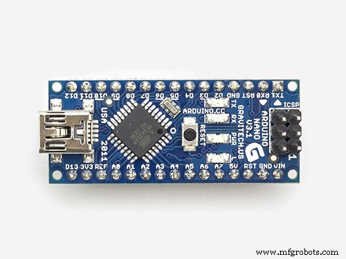
Hoy, construiremos un dispositivo que se conecta a Internet y permite al usuario controlar su hogar de forma remota a través de wifi. Usaremos la placa Arduino (cualquier modelo hará bien el trabajo) con el módulo wifi ESP8266-01 para hacer este dispositivo. ¡Empecemos!
¿Qué es una casa inteligente?
Escenario de trabajo

El Panel de control
Construiremos una página web sencilla que funcionará como un panel de control para que el usuario pueda controlar cualquier electrodoméstico conectado a nuestro sistema. Para construir la página web usaremos:
- HTML
- CSS
- Jquery
El hardware integrado
la página web envía algunos pedidos al ESP8266-01 que funciona como un servidor web conectado a la placa Arduino. Y de acuerdo con los datos entrantes, la placa Arduino realizará algunas acciones como encender la bombilla, apagar el televisor y en esta parte usaremos:
- Arduino
- ESP8266-01
Introducción al ESP8266-01
Como dijimos antes, necesitamos que nuestra placa Arduino se conecte a Internet, pero la versión Arduino Nano que estamos usando hoy no tiene esa característica. Entonces, usaremos el módulo wifi ESP8266-01 para agregar la función wifi a nuestra pequeña placa Arduino.
Hay muchos modelos de módulos wifi ESP, ¿cuál debería elegir? Bueno, casi todos los módulos wifi de la familia ESP funcionarán bien, pero cada uno tiene sus propias características y especificaciones. Te animo a que mires las especificaciones y características de cada una para elegir la más adecuada para tus necesidades.
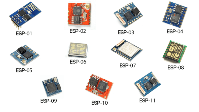
Según mis necesidades, encontré que el ESP8266-01 es el más adecuado y eso es por muchas razones. Es muy famoso en la comunidad de creadores. Como resultado, obtuvo una comunidad en línea muy sólida en la que puede encontrar una respuesta a casi cualquier pregunta o problema que enfrente con este pequeño módulo increíble. Además, su precio es muy económico (alrededor de 1,5 $).
Además, es muy fácil de usar con la placa Arduino, ya que es un módulo wifi en serie que puede comunicarse con la placa Arduino a través de la comunicación en serie. Tiene un microcontrolador incorporado, lo que significa que puede usarlo como un microcontrolador independiente y un módulo wifi en un combo, lo cual es genial. Tiene dos GPIO incorporados. Solo con 1.5 $, obtendrás todas estas características, lo cual es súper genial, en realidad. Echemos un vistazo más de cerca a este módulo.
Pinout ESP8266-01
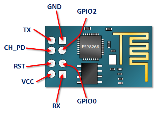
- VCC: conéctese a una fuente de alimentación de + 3.3V. no lo conecte a una fuente de 5 V, se dañará .
- GND: -ve pin, conéctelo a la tierra de su circuito.
- CH_PD: chip habilita el pin - Activo ALTO. conéctelo a un valor lógico ALTO para permitir que el módulo se inicie.
- RST: Pin de reinicio de chip - Activo BAJO, cuando tiró BAJO reinicia el módulo.
- GPIO0, GPIO2: Pines de entrada / salida de uso general.
- Tx: conéctese al Rx del microcontrolador (Arduino) para establecer la comunicación en serie.
- Rx: conéctese al Tx del microcontrolador (Arduino) para establecer la comunicación en serie.
Configuración de ESP8266-01
Como dijimos antes, el módulo ESP8266-01 se comunica con la placa Arduino a través de la comunicación serial, lo que significa que debemos conectarlo con los pines seriales 0, 1 (Tx, Rx) de Arduino. Pero el problema aquí es que estos pines estarán ocupados porque usaremos el monitor serial Arduino junto con el ESP8266-01 para fines de depuración. Entonces, necesitamos encontrar otros dos pines de comunicación en serie para usarlos con el ESP8266-01.
Afortunadamente, Arduino lo hizo fácil. Existe una biblioteca llamada "SoftwareSerial" que se desarrolló para permitir la comunicación en serie en otros pines digitales del Arduino, utilizando software para replicar la funcionalidad. Por ejemplo, al usar esta biblioteca puedo configurar los pines 2, 3 (SoftwareSerial) como Rx y Tx junto con los pines 0, 1 (Hardware Serial).
"SoftwareSerial" La biblioteca funciona muy bien siempre que la velocidad de transmisión sea inferior a 19, 200 baudios. ¡Pero hay un pequeño problema aquí! el módulo wifi ESP8266-01 viene programado de fábrica para comunicarse a una velocidad de 115, 200 baudios, lo que de alguna manera es difícil en la biblioteca “SoftwareSerial” para comunicarse. Por lo tanto, necesitamos reprogramar nuestro módulo wifi para establecer la velocidad de comunicación en 9600 baudios, lo que funciona bastante bien con la biblioteca "SoftwareSerial". Para hacer eso usaremos algunos "comandos AT".
Cambio de la velocidad de comunicación ESP8266-01
Primer paso:sube un programa vacío a la placa Arduino
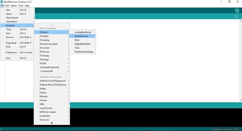
En este paso, estamos cargando un código vacío en la placa Arduino. Solo para estar seguro de que no hay nada ejecutando en segundo plano por la placa Arduino.
Segundo paso:cableado del ESP8266-01 con la placa Arduino
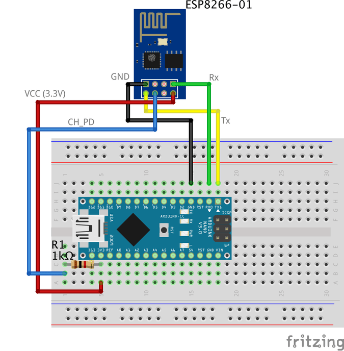
Para reconfigurar el ESP8266-01 y cambiar la velocidad de comunicación (tasa de baudios) usamos los comandos AT. Simplemente, los comandos AT son algunas instrucciones que se utilizan para controlar módems, teléfonos móviles, módulos Bluetooth, módulos wifi, módulos GSM.
con estos comandos podemos obtener información básica sobre nuestro teléfono móvil o módulos GSM como el nombre del fabricante, número de modelo, IMEI, etc. "AT" es una abreviatura de "ATtención" y se llama comandos AT porque cada comando comienza con en". el prefijo "AT" no es parte de los comandos en sí, solo le dice al módulo el inicio de los comandos.
Algunos comandos AT importantes
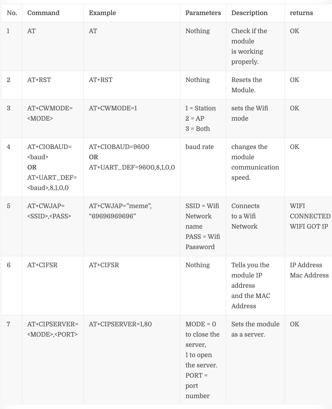
Número de comando "4" depende de su versión de firmware ESP8266-01, si este comando no funciona con usted AT + CIOBAUD = Pruebe este AT + UART_DEF =
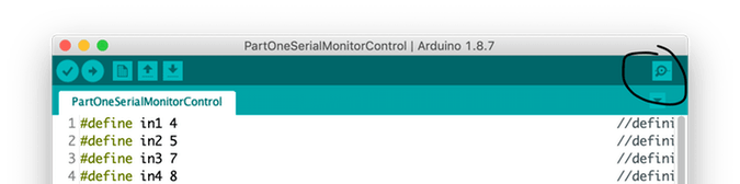
Paso 1:abra el monitor en serie
Paso 2:establezca la velocidad de comunicación en 115, 200 baudios

Como dijimos antes, el ESP proviene del fabricante programado para comunicarse a una velocidad de 115, 200 baudios. Por lo tanto, debemos configurar la velocidad de comunicación de Arduino en 115, 200 también por primera vez solo entonces cambiaremos eso más tarde. Además, debe seleccionar "Tanto NL como CR" .
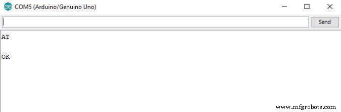
Paso 3:envía "AT" y espera la respuesta para asegurarte de que el módulo ESP te está escuchando.
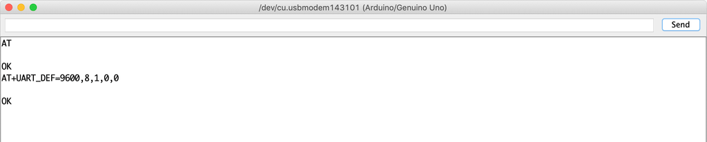
Paso 4:ahora, cambie la velocidad de comunicación ESP8266-01
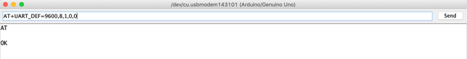
El firmware cargado en mi módulo ESP8266-01 es 1.6. y este comando AT + UART_DEF = funciona bien para mi. Si no funciona con usted, pruebe este AT + CIOBAUD = . Si responde con "Aceptar" ahora la velocidad en baudios de comunicación del módulo ESP cambió de 115, 200 baudios a 9600 baudios. ¡FELICITACIONES!
Cambiemos la velocidad de comunicación del monitor en serie a 9600 y enviemos "AT" nuevamente para ver si el módulo ESP puede escucharnos a la nueva velocidad (9600) o no.
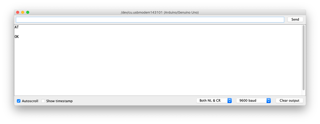
¡MIRA! esta funcionando. el ESP8266-01 ahora puede comunicarse con la placa Arduino a una velocidad de 9600 baudios en lugar de 115, 200 baudios.
Ahora, intentemos conectarnos con la red Wifi
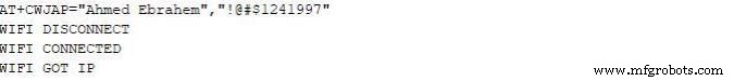
Una vez que presione enter, el ESP8266-01 buscará esta red y se conectará con ella. Si el proceso tiene éxito, devolverá este
WIFI CONECTADO
WIFI GOT IP
En este punto, cambiamos con éxito la velocidad de comunicación ESP8266-01 de 115, 200 baudios a 9600 baudios. Ahora, necesitamos construir el panel de control (página web) que el usuario utilizará para controlar sus electrodomésticos. Entonces, ¡construyémoslo!
¿Qué es Internet?
En realidad, Internet es un cable enterrado bajo tierra, puede ser fibra óptica, cobre o incluso un satélite, pero Internet es simplemente un cable.Cualquier dos computadoras conectadas a ese cable pueden comunicarse. Si la computadora está conectada directamente a ese cable se llama servidor y si no está conectado directamente a ese cable, se llama cliente .
Servidor: es una computadora especial que ejecuta un sistema operativo específico como Apache, esta computadora especial guarda algunas páginas web, archivos, bases de datos en su unidad de disco. cualquier servidor conectado a Internet tiene una dirección IP única como 172.217.171.228 , la dirección IP es como un número de teléfono que ayuda a las personas a encontrarse fácilmente. Dado que esa dirección IP no es muy fácil de recordar para los humanos. Entonces, le dimos un nombre google.com (Nombre de dominio).
Cliente: Es una computadora como la que usamos tú y yo todos los días, está conectada indirectamente a Internet a través de un proveedor de servicios de Internet (ISP) y también tiene una dirección IP única.
Escenario de trabajo
Simplemente, comienza con una solicitud enviada desde un navegador web (Cliente) como google chrome, firefox y termina con la respuesta recibida del servidor web.
Ingresó la URL del sitio web makesomestuff.org en un navegador desde una computadora (cliente), luego este navegador envía una solicitud al servidor web que aloja el sitio web, el servidor web luego devuelve una respuesta que contiene una página HTML o cualquier otro formato de documento al navegador para mostrar eso.
Exactamente, eso es lo que tenemos que hacer hoy en nuestro proyecto. Necesitamos enviar una solicitud desde el navegador web (Cliente) al ESP8266-01 (Servidor web) que ambos están conectados a la misma red local. Esta solicitud contiene algunos datos que le dicen al Arduino qué hacer para encender o apagar una bombilla. Entonces, ¡construyamos la página web!
Construyendo la página web
Para construir nuestra página web tenemos que lidiar con HTML, CSS, Javascript. si nunca antes escuchó sobre estos nombres, no se preocupe, lo tengo.
HTML: Significa "lenguaje de marcado de hipertexto", lo usamos para construir la estructura principal de cualquier página web. Como agregar algunos botones, imágenes, párrafos, encabezados, tablas y muchos más elementos. consta de una serie de elementos que le indican al navegador cómo mostrar el contenido de la página web. estos elementos se representan mediante algo llamado etiquetas.

CSS: Significa hoja de estilo en cascada. Después de construir la estructura principal de la página web, necesita hacer que esta estructura se vea bien aquí viene CSS para hacer algo de estilo. es un lenguaje que describe el estilo de un elemento HTML. consta de algunos selectores y bloques de desaceleración.

Javascript: es un lenguaje de programación que usaremos para hacer la página web más interactiva como agregar algunas animaciones, mapas y nos permite hacer cosas complejas en la página web. Principalmente, lo usaremos hoy para enviar una solicitud HTTP desde el cliente (navegador web) al servidor web (ESP8266-01) para realizar algunas acciones como encender o apagar una bombilla.

Construya la estructura de la página web
Para comprender fácilmente la próxima explicación, recomiendo leer este interesante Introducción a HTML .
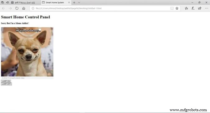
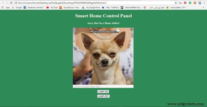
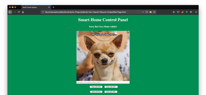
Como vemos nuestro panel de control es muy simple, contiene dos encabezados cada uno tiene un tamaño diferente, una imagen y dos botones uno para encender un LED y el segundo para apagarlo.
Código
Smart Home System Panel de control de Smart Home
Lo siento, pero ¡Soy un adicto a los memes!

Explicación del código
- : declaración define que este documento es un documento HMTL5.
- : el elemento raíz de una página HTML.
- : El elemento contiene metainformación sobre la página.
-
: elemento especifica el título del documento. este título aparece en la pestaña del navegador de la página web. - : El elemento contiene el contenido visible de la página web.
-
:
elemento define un elemento grande. -
:
elemento define un encabezado más pequeño. cuando el valor del encabezado disminuye, la fuente disminuye. -
: elemento agrega una imagen a la página web. la imagen que desea mostrar debe estar en la misma carpeta del proyecto.
-
: avanzar el cursor a una nueva línea. -
: elemento agrega un botón al contenido de la página.
Cada botón de nuestra página web tiene dos atributos muy importantes el id y la clase atributos. hablaremos sobre por qué asignamos estos dos valores a los botones en la explicación del código de Jquery.
Diseñar la página web
Para comprender fácilmente la próxima explicación, recomiendo leer este interesante Introducción a CSS .
Ahora, la página web se ve mejor (NO DEMASIADO xD) le dimos un color de fondo verde fresco, alineamos el contenido de la página en el centro y cambiamos el color de la fuente de los encabezados y la familia de fuentes, lo que hizo que la página web estuviera más viva. Usamos CSS para hacer todas estas cosas de estilo.
Código
Smart Home System Panel de control de casa inteligente
¡Lo siento, pero soy un adicto a los memes!

Explicación del código
Agregamos algunas líneas de código para que nuestra página web se vea mejor. Agregamos style ="background-color:seagreen; color:seashell; text-align:center;" dentro del cuerpo etiqueta para hacer que todo el contenido de la página web en el centro de la página y establecer el color de fondo en verde mar también para establecer el color de la fuente en concha .
Además, agregamos style ="margin:10px;" dentro de las dos etiquetas de botón para establecer un margen de 10 píxeles alrededor de los cuatro lados de cada botón.
Envío de una solicitud al servidor web
Para comprender fácilmente la próxima explicación, recomiendo leer este interesante Introducción a Jquery .
Ahora, después de construir la estructura de nuestra página web y darle estilo, necesitamos agregar alguna funcionalidad a los dos botones que agregamos anteriormente en la página web. necesitamos cuando el usuario hace clic en el botón "LAMP ON", su navegador envía una solicitud que contiene algunos datos únicos al servidor (ESP8266-01), estos datos únicos le dicen al Arduino que encienda la lámpara. Lo mismo con el segundo botón "LAMP OFF" cuando el usuario hace clic en él, el navegador enviará una solicitud que contiene algunos datos únicos al servidor (ESP8266-01), estos datos únicos le dicen al Arduino que apague la lámpara. Echemos un vistazo al código.
Smart Home System Panel de control de Smart Home
¡Lo siento, pero soy un adicto a los memes!
Explicación del código
Primero lo primero, necesitamos importar la biblioteca Jquery en nuestro código. Entonces, agregamos esta línea en la etiqueta de encabezado .
Toda la magia ocurre en esta parte interesante.
-
$ (". botón"). haga clic en (función () {
Cuando el usuario hace clic en cualquier botón asociado con la clase “botón” , active la siguiente función.
-
var p =$ (this) .attr ('id');
Obtenga el valor del atributo del botón en el que se hizo clic "id" y guárdelo dentro de la "p" variable.
-
pin:p
Ponga el valor de la variable "p" en un diccionario (valor-clave), su clave es "pin" y el valor es el valor de la variable "p".
-
$ .get ("http://172.20.10.11:80/", {pin:p});});
Luego, envíe una solicitud GET al servidor web cuya dirección IP es "172.20.10.11". este OBTENER la solicitud contiene el valor del atributo id botón presionado.
En caso de que el usuario presione el botón "LAMP ON", este valor de identificación será 111, por lo que el encabezado de la solicitud GET contendrá algunos datos como este pin =111 . ¡mira la siguiente figura!
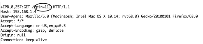
En el lado opuesto, si el usuario presionó el botón "LAMP OFF", la solicitud contendrá estos datos pin =110 .
Lógica de código
Sé que estás preguntando ahora por qué diablos eligió 111 y 110 ¿específicamente? Ok, déjame responderte fam. De hecho, el número 111 y 110 se divide en dos partes.
- Primera parte: son los dos primeros números que en ambos casos serán "11", se refiere al número de pin de Arduino al que está conectada la carga que necesito controlar.
- Segunda parte: es el tercer número que cambia entre 1 y 0 según el botón en el que se haga clic. Y se refiere al estado del pin (ACTIVADO o DESACTIVADO).
En el código Arduino, recibiremos estos datos y separaremos estas dos partes entre sí y guardaremos cada parte en una variable diferente, la parte uno en la variable pinNumber y la segunda parte en la variable pinState , luego escribiremos esta simple línea de código para controlar la carga conectada digitalWrite (pinNumber, pinState);
Conectando la carga
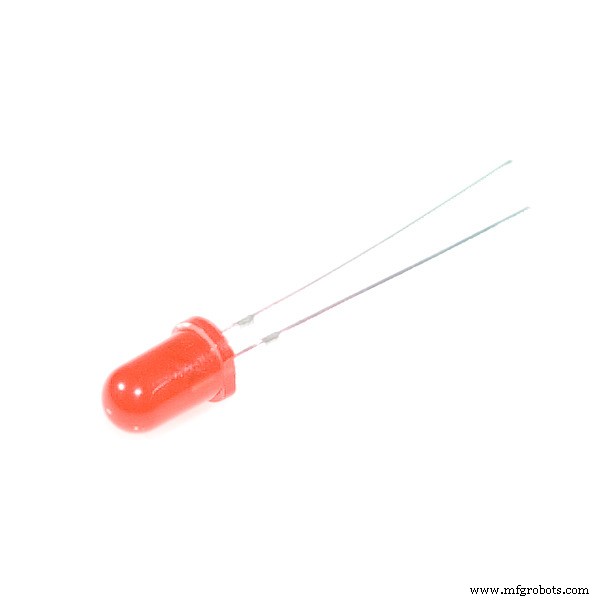
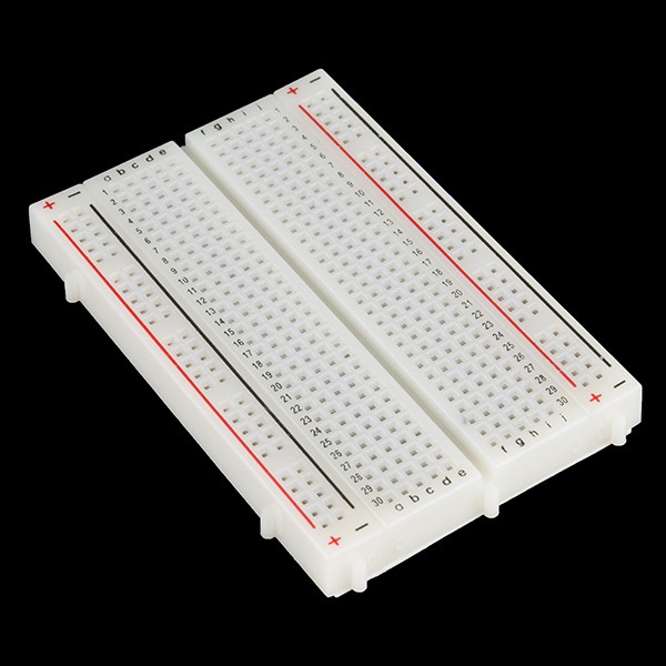
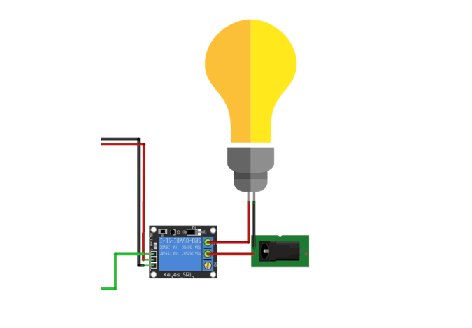
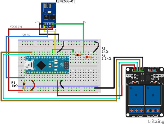
Ahora, necesitamos conectar la carga con la placa Arduino para controlarla. Antes de conectar cualquier dispositivo de alto voltaje como el aire acondicionado o incluso el televisor, necesitamos probar nuestro circuito y el código con algunas cosas de bajo voltaje como LED solo para asegurarnos de que todo esté funcionando bien. Aquí está el diagrama de cableado
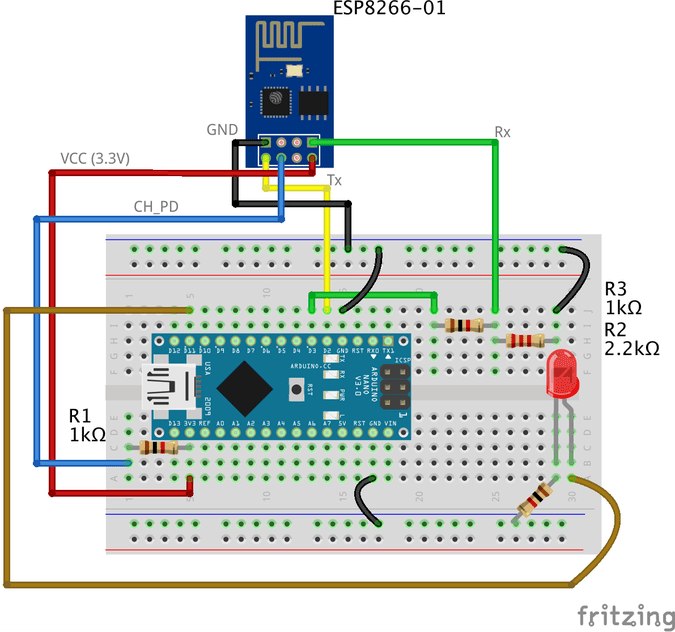
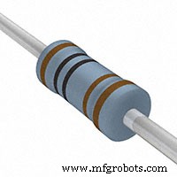
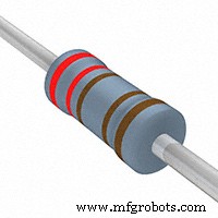
El cableado es bastante simple, estamos conectando la pata positiva del LED al pin digital 11 de Arduino y la pata negativa al GND a través de una resistencia de 1k ohmios.
Código Arduino
#include // incluyendo la biblioteca SoftwareSerial le permitirá usar el pin no. 2,3 como Rx, Tx. SoftwareSerial esp8266 (2,3); // establece el Rx ==> Pin 2; TX ==> Pin3. #define serialCommunicationSpeed 9600 // <=========define una constante denominada "serialCommunicationSpeed" con un valor de 9600. Se refiere a la velocidad de comunicación en serie del software y hardware (velocidad en baudios). #define DEBUG true // crea una constante llamada "DEBUG" y su valor es true. lo usaremos más tarde. int redLED =12; // asigna una variable llamada "redLED" con un valor entero 12, se refiere al pin al que está conectado el LED rojo. int blueLED =11; // asigna una variable llamada "blueLED" con un valor entero 11, se refiere al pin al que está conectado el LED azul. configuración vacía () {pinMode (rojoLED, SALIDA); // establece el pin número 12 como pin de salida. pinMode (blueLED, SALIDA); // establece el pin número 11 como pin de salida. digitalWrite (rojoLED, BAJO); // apaga el LED rojo al comienzo del programa. digitalWrite (blueLED, HIGH); // enciende el LED azul al inicio del programa. Serial.begin (serialCommunicationSpeed); // inicia la comunicación serial del hardware (0, 1) a una velocidad de 9600. esp8266.begin (serialCommunicationSpeed); // inicia la comunicación en serie del software (2, 3) a la velocidad 9600. InitWifiModule (); // Llame a esta función definida por el usuario "InitWifiModule ()" para inicializar una comunicación entre el ESP8266 y su punto de acceso (enrutador doméstico o incluso su punto de acceso móvil). digitalWrite (blueLED, LOW); // después de finalizar la inicialización con éxito, apague el LED azul (solo un indicador). } void loop () // nuestro programa principal, algo de diversión está a punto de comenzar) {if (esp8266.available ()) // si hay datos recibidos y almacenados en el búfer de recepción en serie, vaya y ejecute el cuerpo de la condición if . Si no es así, no ejecutes el cuerpo de la condición si. { if(esp8266.find("+IPD,")) //search for the "+IPD," string in the incoming data. if it exists the ".find()" returns true and if not it returns false. { delay(1000); //wait 1 second to fill up the buffer with the data. int connectionId =esp8266.read()-48; //Subtract 48 because the read() function returns the ASCII decimal value. And 0 (the first decimal number) starts at 48. We use it to convert from ASCI decimal value to a character value. esp8266.find("pin="); //Advance the cursor to the "pin=" part in the request header to read the incoming bytes after the "pin=" part which is the pinNumer and it's state. int pinNumber =(esp8266.read()-48)*10; //read the first Byte from the Arduino input buffer(i.e. if the pin 12 then the 1st number is 1) then multiply this number by 10. So, the final value of the "pinNumber" variable will be 10. pinNumber =pinNumber + (esp8266.read()-48); //read the second Byte from the Arduino input buffer(i.e. if the pin number is 12 then the 2nd number is 2) then add this number to the first number. So, the final value of the "pinNumber" variable will be 12. int statusLed =(esp8266.read()-48); //read the third byte from the Arduino input buffer. then save it inside the "statusLed" variable. At any case, it will be 1 or 0. digitalWrite(pinNumber, statusLed); //then turn the LED at "pinNumber" on or off depending on the "statusLed" variable value. Serial.println(connectionId); //print the "connectionId" value on the serial monitor for debugging purposes. Serial.print(pinNumber); //print the "pinNumber" value on the serial monitor for debugging purposes. Serial.print (""); //print some spaces on the serial monitor to make it more readable. Serial.println(statusLed); //print the "statusLed" value on the serial monitor for debugging purposes. String closeCommand ="AT+CIPCLOSE="; //close the TCP/IP connection. closeCommand+=connectionId; //append the "connectionId" value to the string. closeCommand+="\r\n"; //append the "\r\n" to the string. it simulates the keyboard enter press. sendData(closeCommand,1000,DEBUG); //then send this command to the ESP8266 module to excute it. } } } /****************************************************************************************************************************************************************************************** * Name:sendData * Description:this Function regulates how the AT Commands will ge sent to the ESP8266. * * Params:command - the AT Command to send * - timeout - the time to wait for a response * - debug - print to Serial window?(true =yes, false =no) * * Returns:The response from the esp8266 (if there is a reponse) */ String sendData(String command, const int timeout, boolean debug) { String response =""; //initialize a String variable named "response". we will use it later. esp8266.print (comando); //send the AT command to the esp8266 (from ARDUINO to ESP8266). tiempo int largo =millis (); //get the operating time at this specific moment and save it inside the "time" variable. while( (time+timeout)> millis()) //excute only whitin 1 second. { while(esp8266.available()) //is there any response came from the ESP8266 and saved in the Arduino input buffer? { char c =esp8266.read(); //if yes, read the next character from the input buffer and save it in the "response" String variable. response+=c; //append the next character to the response variabl. at the end we will get a string(array of characters) contains the response. } } if(debug) //if the "debug" variable value is TRUE, print the response on the Serial monitor. { Serial.print(response); } return response; //return the String response. } /****************************************************************************************************************************************************************************************** * Name:InitWifiModule * Description:this Function gives the commands that we need to send to the sendData() function to send it. * * Params:Nothing. * * Returns:Nothing (void). */ void InitWifiModule() { sendData("AT+RST\r\n", 2000, DEBUG); //reset the ESP8266 module. //delay(1000); sendData("AT+CWJAP=\"PUT YOUR SSID\",\"PUT YOUR PASSWORD\"\r\n", 2000, DEBUG); //connect to the WiFi network. delay (3000); sendData("AT+CWMODE=1\r\n", 1500, DEBUG); //set the ESP8266 WiFi mode to station mode. delay (1000); sendData("AT+CIFSR\r\n", 1500, DEBUG); //Show IP Address, and the MAC Address. delay (1000); sendData("AT+CIPMUX=1\r\n", 1500, DEBUG); //Multiple conections. delay (1000); sendData("AT+CIPSERVER=1,80\r\n", 1500, DEBUG); //start the communication at port 80, port 80 used to communicate with the web servers through the http requests. } code explanation
the code is pretty straightforward, we implemented two different functions InitWifiModule() and sendData()
The sendData() function job is regulating how the AT commands will get sent to the ESP8266-01 module.
the InitWifiModule() function job is to provide the sendData() function the AT commands that we need to send to the ESP8266-01.
in the loop() function we read the income HTTP request header and search for the “+IPD, ” which means that the request has successfully arrived, then we read the pin value which it will be “111” if the user clicked the “LAMP ON” button and “110” if the user clicked “LAMP OFF” button.
Don’t forget to put your wifi SSID and Password in the Arduino code line no. 103 sendData("AT+CWJAP=\"PUT YOUR SSID\",\"PUT YOUR PASSWORD\"\r\n", 2000, DEBUG);
For more code explanation please read the comments in the code, it’s well documented
Cómo funciona
After uploading the code to the Arduino board, open the Serial monitor and read the responses that the ESP module is sending.
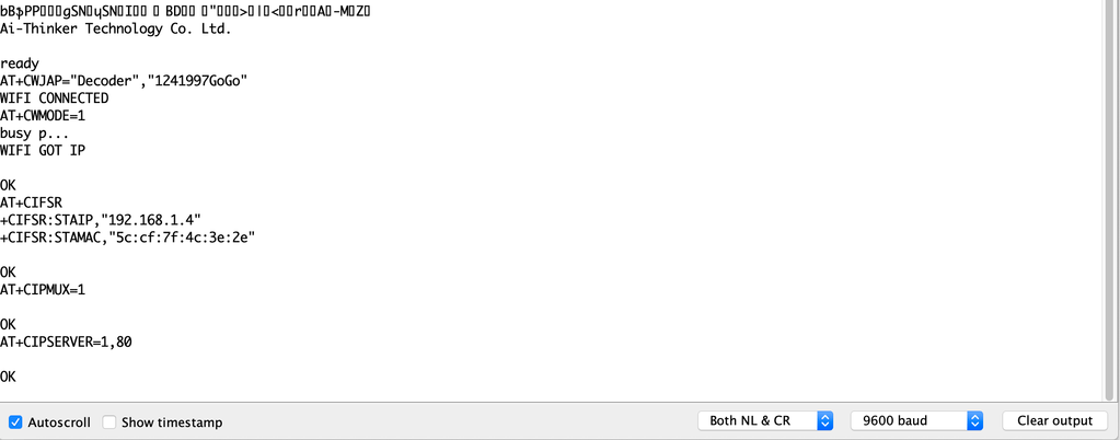
at the beginning of the program, if you see something like the previous figure with “OK” at the end of the page, it means that the ESP8266-01 module is successfully connected to your wifi (Access point) and got an IP and MAC address. Now, you can open your fancy web page and try to control some stuff 😉
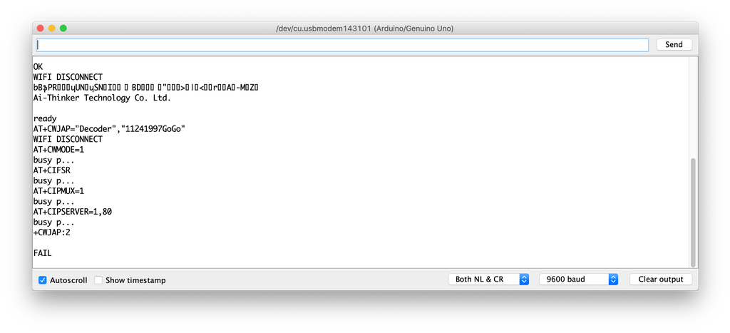
But, if you see something like the previous figure with a “FAIL” or “ERROR” at the end of the page, it means that your ESP module cant connect to your wifi (Access point) for some reasons, try to check if entered the right SSID and password for your network.
Adding a High Voltage Load
After we tested our code and got sure that everything is working like a charm, we need to replace this boring LED with a High voltage load like an air conditioner, TV or a light bulb. But to control all of these high voltage appliances we have to deal with relays .
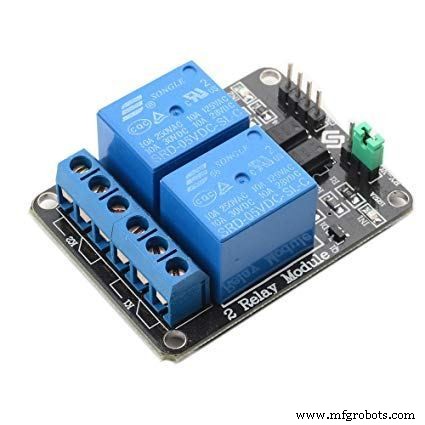
What’s and why relays? Ok, the relay is a mechanical switch, which is toggled on or off by energizing a coil. it’s mainly used to control a high powered circuit using a low power signal (5V or 0V). So we can control a high powered device like an air conditioner or an AC lamp turning it on or off only by a 5V or 0V signal. Which is amazing!
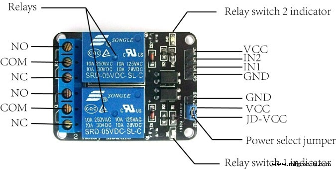
The Two-channel relay module has two control pins(IN1, IN2) these pins should get connected to two Arduino digital pins to control the state of the two coils, closes or opens the load circuit.
At the opposite side of the relay module, the COM(common) should get connected to one end of the load. the other end of the load is either connected to the NC(Normally Close) or NO(Normally open) , if connected to the NO the load remains Disconnected before trigger and vice versa.
Wiring Diagram
As you see, we are using a two-channel relay module that gives us the ability to control two different AC loads. We are connecting the first relay at digital output pin11(Arduino) and the second relay to digital output pin 12(Arduino)
We will make a small modification to our web page, we will add another two buttons(ON and OFF) to control the second connected load.
Smart Home System Smart Home Control Panel
Sorry But I'm a Meme Addict!
How It Works
Just like the last trial, You upload the Arduino code to the board (if not uploaded yet) and open the serial monitor and make sure that your ESP module is connected successfully to your access point and got an IP and MAC address.
Then open your fancy web page and start controlling your stuff 😉
Make it more professional!
What about transferring our breadboard circuit to a professional printed circuit board (PCB) to make our project more rigid and solid, I designed the project circuit using Autodesk Eagle software. all the PCB files are open-source you can access it from this link:https://www.pcbway.com/project/shareproject/IoT_Using_Arduino_and_ESP8266_01.html
Because we love open source 😉
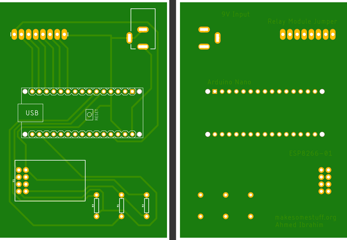
You can order your own PCB From PCBWay company these guys have a very good reputation in this field and they ship to more than 170 countries around the world with reasonable prices. all you have to do is to open the project PCB files link and press “Add to cart”. That’s it!
Solución de problemas
if your ESP Module is successfully connected to your access point but there is no action happens when you click the web page buttons
- make sure that you are sending the request from your web browser from port 80(HTTP). example:
$.get("http://192.168.1.4:80/"
- make sure that your PC or Laptop and the ESP module is connected to the same Access point.
- In Jquery code, make sure that you wrote the right ESP module IP address.
- Make sure that you are connecting the load at Arduino digital pins 11 and 12.
- Don’t forget to save the Web page code file after any change or modification, and reload the web page in the web browser after any code modification to take effect.
Final
We are done! in today’s tutorial, we learned how to build a simple web page using HTML, CSS, and jquery. Also, we learned how to control an AC load wirelessly from a web-based control panel, and how to use the awesome ESP8266-01 Wifi module with the Arduino board.
you wanna see more Tutorials and open source projects you can also visit my blog www.makesomestuff.org
Lastly, if you have any questions drop it in the comments section below, I will be more than happy to hear from you 😉
Código
- Web Page
- Final Arduino Code
Web PageHTML
Smart Home System Smart Home Control Panel
Sorry But I'm a Meme Addict!
Final Arduino CodeArduino
#include//including the SoftwareSerial library will allow you to use the pin no. 2,3 as Rx, Tx.SoftwareSerial esp8266(2,3); //set the Rx ==> Pin 2; TX ==> Pin3.#define serialCommunicationSpeed 9600 // <=========define a constant named "serialCommunicationSpeed" with a value 9600. it referes to the Software and hardware serial communication speed(baud rate).#define DEBUG true //make a constant named "DEBUG" and it's value true. we will use it later.int redLED =12; //assign a variable named "redLED" with an integer value 12, it refers to the pin which the red LED is connected on.int blueLED =11; //assign a variable named "blueLED" with an integer value 11, it refers to the pin which the blue LED is connected on.void setup(){ pinMode(redLED,OUTPUT); //set the pin number 12 as an output pin. pinMode(blueLED,OUTPUT); //set the pin number 11 as an output pin. digitalWrite(redLED,LOW); //turn the red LED off at the beginning of the program. digitalWrite(blueLED,HIGH); //turn the blue LED on at the beginning of the program. Serial.begin(serialCommunicationSpeed); //begin the Hardware serial communication (0, 1) at speed 9600. esp8266.begin(serialCommunicationSpeed); //begin the software serial communication (2, 3) at speed 9600. InitWifiModule(); //call this user-defined function "InitWifiModule()" to initialize a communication between the ESP8266 and your access point (Home Router or even your mobile hotspot). digitalWrite(blueLED,LOW); //after finishing the initialization successfully, turn off the blue LED (just an indicator).}void loop() //our main program, some fun are about to start){ if(esp8266.available()) //if there's any data received and stored in the serial receive buffer, go and excute the if-condition body. If not, dont excute the if-condition body at all. { if(esp8266.find("+IPD,")) //search for the "+IPD," string in the incoming data. if it exists the ".find()" returns true and if not it returns false. { delay(1000); //wait 1 second to fill up the buffer with the data. int connectionId =esp8266.read()-48; //Subtract 48 because the read() function returns the ASCII decimal value. And 0 (the first decimal number) starts at 48. We use it to convert from ASCI decimal value to a character value. esp8266.find("pin="); //Advance the cursor to the "pin=" part in the request header to read the incoming bytes after the "pin=" part which is the pinNumer and it's state. int pinNumber =(esp8266.read()-48)*10; //read the first Byte from the Arduino input buffer(i.e. if the pin 12 then the 1st number is 1) then multiply this number by 10. So, the final value of the "pinNumber" variable will be 10. pinNumber =pinNumber + (esp8266.read()-48); //read the second Byte from the Arduino input buffer(i.e. if the pin number is 12 then the 2nd number is 2) then add this number to the first number. So, the final value of the "pinNumber" variable will be 12. int statusLed =(esp8266.read()-48); //read the third byte from the Arduino input buffer. then save it inside the "statusLed" variable. At any case, it will be 1 or 0. digitalWrite(pinNumber, statusLed); //then turn the LED at "pinNumber" on or off depending on the "statusLed" variable value. Serial.println(connectionId); //print the "connectionId" value on the serial monitor for debugging purposes. Serial.print(pinNumber); //print the "pinNumber" value on the serial monitor for debugging purposes. Serial.print (""); //print some spaces on the serial monitor to make it more readable. Serial.println(statusLed); //print the "statusLed" value on the serial monitor for debugging purposes. String closeCommand ="AT+CIPCLOSE="; //close the TCP/IP connection. closeCommand+=connectionId; //append the "connectionId" value to the string. closeCommand+="\r\n"; //append the "\r\n" to the string. it simulates the keyboard enter press. sendData(closeCommand,1000,DEBUG); //then send this command to the ESP8266 module to excute it. } }}/******************************************************************************************************************************************************************************************* Name:sendData* Description:this Function regulates how the AT Commands will ge sent to the ESP8266.* * Params:command - the AT Command to send * - timeout - the time to wait for a response * - debug - print to Serial window?(true =yes, false =no)* * Returns:The response from the esp8266 (if there is a reponse)*/String sendData(String command, const int timeout, boolean debug){ String response =""; //initialize a String variable named "response". we will use it later. esp8266.print (comando); //send the AT command to the esp8266 (from ARDUINO to ESP8266). tiempo int largo =millis (); //get the operating time at this specific moment and save it inside the "time" variable. while( (time+timeout)> millis()) //excute only whitin 1 second. { while(esp8266.available()) //is there any response came from the ESP8266 and saved in the Arduino input buffer? { char c =esp8266.read(); //if yes, read the next character from the input buffer and save it in the "response" String variable. response+=c; //append the next character to the response variabl. at the end we will get a string(array of characters) contains the response. } } if(debug) //if the "debug" variable value is TRUE, print the response on the Serial monitor. { Serial.print(response); } return response; //return the String response.}/******************************************************************************************************************************************************************************************* Name:InitWifiModule* Description:this Function gives the commands that we need to send to the sendData() function to send it.* * Params:Nothing.* * Returns:Nothing (void).*/void InitWifiModule(){ sendData("AT+RST\r\n", 2000, DEBUG); //reset the ESP8266 module. //delay(1000); sendData("AT+CWJAP=\"Decoder\",\"1241997GoGo\"\r\n", 2000, DEBUG); //connect to the WiFi network. delay (3000); sendData("AT+CWMODE=1\r\n", 1500, DEBUG); //set the ESP8266 WiFi mode to station mode. delay (1500); sendData("AT+CIFSR\r\n", 1500, DEBUG); //Show IP Address, and the MAC Address. delay (1500); sendData("AT+CIPMUX=1\r\n", 1500, DEBUG); //Multiple conections. delay (1500); sendData("AT+CIPSERVER=1,80\r\n", 1500, DEBUG); //start the communication at port 80, port 80 used to communicate with the web servers through the http requests.}
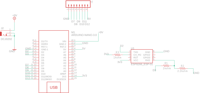
Esquemas
Proceso de manufactura
- TinyML-Language Detector basado en Edge Impulse y Arduino
- Juego de giroscopio Arduino con MPU-6050
- Dados digitales Arduino
- Máquina de LEVITACIÓN ULTRASÓNICA usando ARDUINO
- Voltímetro de bricolaje con Arduino y un teléfono inteligente
- Monitor de frecuencia cardíaca con IoT
- IOT - Smart Jar usando ESP8266, Arduino y sensor ultrasónico
- Sonda usando arduino y visualización en procesamiento IDE
- Control del brillo del LED usando Bolt y Arduino
- Control total de su televisor con Alexa y Arduino IoT Cloud
- Radio FM usando Arduino y RDA8057M