


Cultívelo usted mismo | GIY
Componentes y suministros
 |
| × | 1 | |||
 |
| × | 1 | |||
 |
| × | 1 | |||
 |
| × | 4 | |||
 |
| × | 1 | |||
 |
| × | 1 | |||
 |
| × | 1 | |||
 |
| × | 1 | |||
 |
| × | 1 | |||
 |
| × | 1 |
Herramientas y máquinas necesarias
| |
| |||
| |
|
Aplicaciones y servicios en línea
 |
| |||
 |
|
Acerca de este proyecto
Introducción
Me sentí muy inspirado después de ver la charla TED sobre agricultura digital, impartida por el director de la Iniciativa de agricultura abierta del MIT, Caleb Harper, que planteó el tema: Esta computadora hará crecer sus alimentos en el futuro . La pregunta más importante que se abordó en su charla y que realmente me inspiró fue ¿Qué pasaría si pudiéramos cultivar alimentos deliciosos y ricos en nutrientes en interiores en cualquier parte del mundo? ¡Y aquí nació la idea!
Entonces, lo que estoy tratando de hacer es algo así como una caja o incubadora, que puede crear las condiciones climáticas ideales necesarias para el crecimiento, proporcionando exactamente la cantidad de luz y nutrientes que necesita una planta. Quiero construir un emulador de luz solar, un sistema de riego y un controlador de clima envueltos en un diseño elegante y moderno.

Estoy planeando lograr los resultados deseados mediante la implementación de la siguiente tecnología:
Haz crecer la luz LED - La clorofila en las plantas responde principalmente a solo dos longitudes de onda, representadas por 450 nm y 650 nm. El sistema LED que planeo usar tendrá una combinación de luces LED rojas y azules para proporcionar la combinación perfecta para ayudar tanto en el crecimiento vegetativo como en la floración.
Atomizador ultrasónico (fabricante de niebla):quiero usar un nuevo método de riego, que descubrí por mí mismo recientemente, llamado aeroponía (FogPonics) que riega las plantas a través de una niebla infundida con fertilizantes.
Dosificación automática de nutrientes - Este sistema dosificará automáticamente los nutrientes para las plantas exactamente cuando lo necesiten.
Sistema de detección de agua - Quiero equipar mi sistema con sensores de pH y TDS (sólidos disueltos totales) para ayudar a mantener un valor de pH equilibrado en el depósito de agua que se adapte mejor a las plantas, así como saber y alertar cuándo dosificar los nutrientes.
Sistema de intercambio de agua - el sistema debe estar equipado con una conexión para cambios automáticos de agua. Quiero que este proceso sea fácil y controlado con solo hacer clic en un botón.
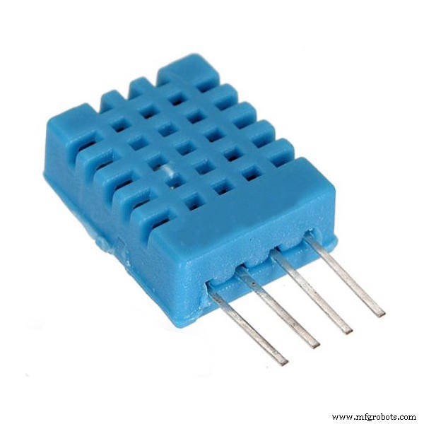
Sistema de control de aire - Permite tener un control preciso de la temperatura y la humedad dentro del sistema, hasta un solo grado. La tecnología detrás implica el uso de un sensor de temperatura / humedad como DHT22 o DHT11 para recibir los datos, y un ventilador con una bobina para regularlos en consecuencia.
Aplicación móvil - ¡Tengo muchas ganas de crear una aplicación por primera vez en mi vida! Esta aplicación debe incluir información en tiempo real sobre el nivel de pH, temperatura, humedad, nutrientes, ppm, etc. y una representación gráfica a lo largo del tiempo para realizar un seguimiento de las estadísticas y compartir el progreso del crecimiento en las redes sociales. También quiero implementar alertas inteligentes que me avisen cuando el sistema necesite mi implicación. ¡También quiero no solo recibir la representación de datos en mi teléfono, sino también poder configurar las condiciones climáticas dentro del sistema!
Desafortunadamente, no soy el primero a quien se le ocurrió este tipo de idea, pero ¡la mejor manera de tener una idea creativa es mejorar las existentes!
Hay varios proyectos similares disponibles en el mercado; sin embargo, a pesar de todas las ventajas individuales, también tienen algunas desventajas, como ocupar demasiado espacio o ser demasiado pequeños, demasiado costosos, cultivar solo una cosecha a la vez, etc. Investigar y analizar cuidadosamente las fortalezas y debilidades de los proyectos disponibles, y considerando la respuesta del mercado, quiero crear un nuevo sistema avanzado de código abierto, que reducirá las desventajas e implementará solo las mejores características.
Muy ambicioso, ¿no? Pero intentémoslo
Experimentos
¡Tratar con plantas consume mucho tiempo! Por lo general, requieren de varias semanas a varios meses para crecer, ¡y tengo que estar listo para eso!
Porque ya sé lo que quiero construir para mi proyecto final, tengo que cuidarlo con anticipación y no dejarlo todo para el último momento. ¡Por eso, comenzaré a probar y experimentar lo antes posible!
Lo primero que quiero averiguar es el hecho de que el cultivo de plantas con niebla rica en nutrientes y cultivar luces LED ¡Es mejor que un sistema convencional en suelo y luz solar natural! En teoría, este debería ser exactamente el caso, ¡pero no creo en nada hasta que lo intento!
Entonces decidí comenzar mi propio experimento, que requerirá algo de tiempo, y consiste en dividir las plantas en varios grupos:
- (Suelo + Luz solar) - este grupo crecerá en condiciones absolutamente naturales, se plantará en tierra y se colocará en el alféizar de la ventana.
- (Niebla + Luz solar) - este grupo se colocará en un recipiente, que tendrá una niebla rica en nutrientes en el interior, y también se colocará en el mismo alféizar de la ventana
- (Luz LED de suelo + cultivo) - este grupo estará en el suelo, pero usará luz LED de cultivo artificial en lugar de la luz solar
- (Niebla + Luz LED de crecimiento) - se supone que es el HÉROE group) Debido a que mi sistema futuro implementará estas dos características, la luz LED de crecimiento y la nube de niebla rica en nutrientes, espero descubrir que esta combinación mostrará los mejores resultados.
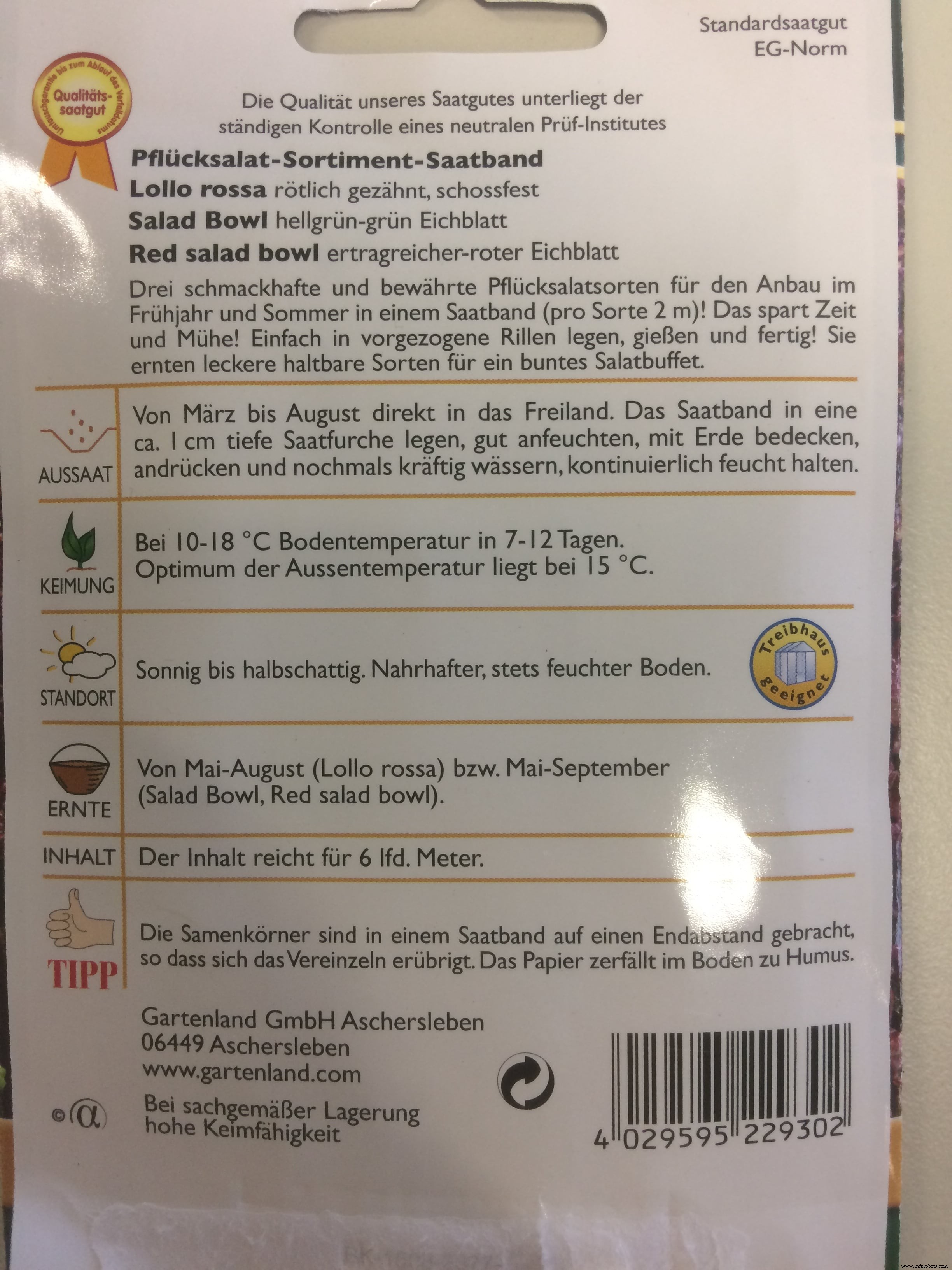
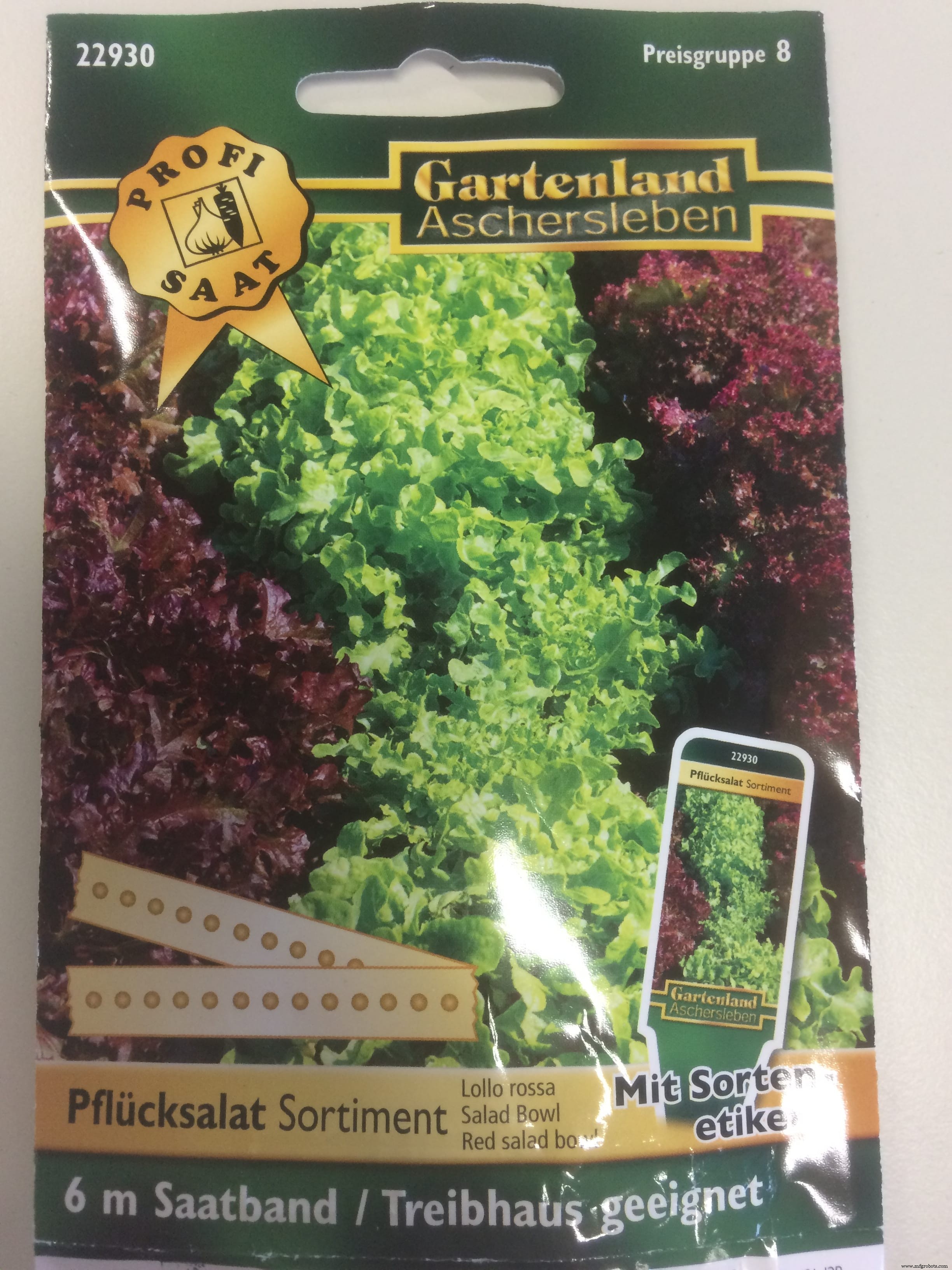
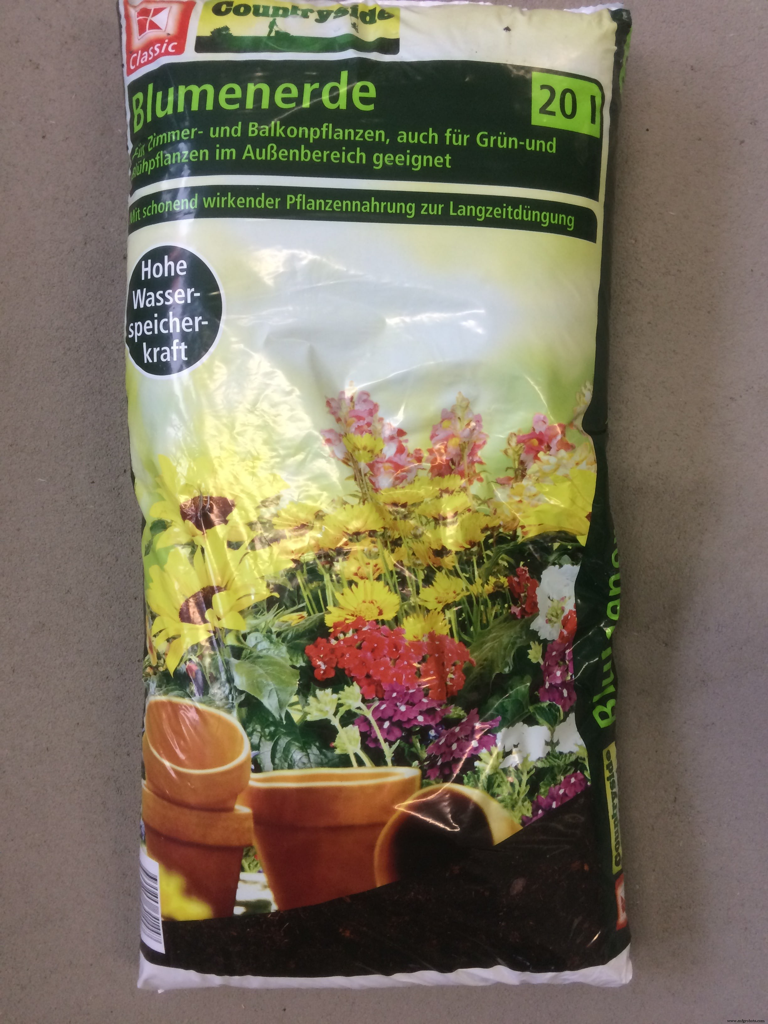
En la tienda local alemana Kaufland, en el departamento de plantas, compré las semillas de hierbas mixtas. Estos serán mis bebés de prueba:p
Fue la primera vez en mi vida que planté algo:¡D no me juzgues si hice algo mal!)
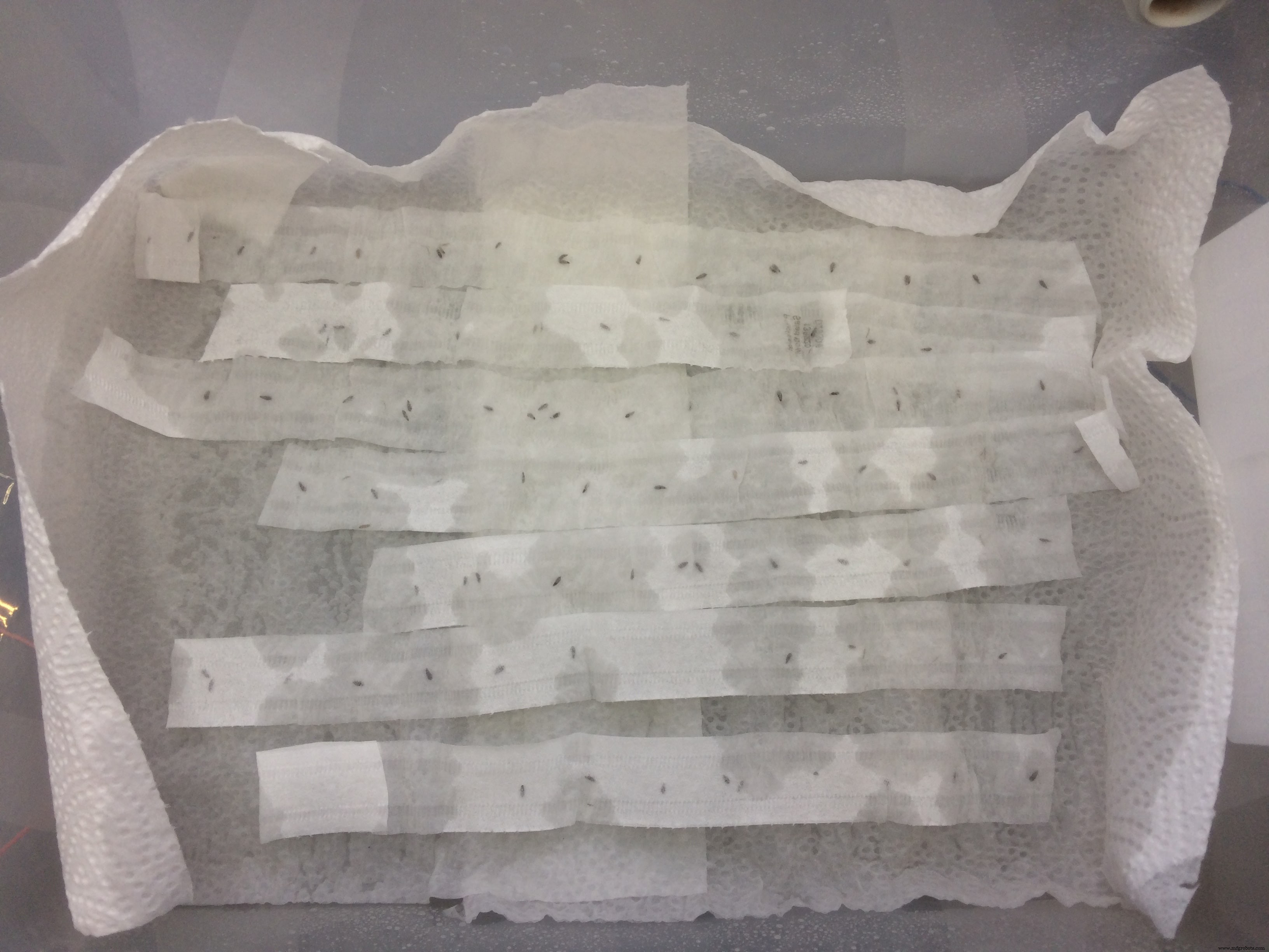
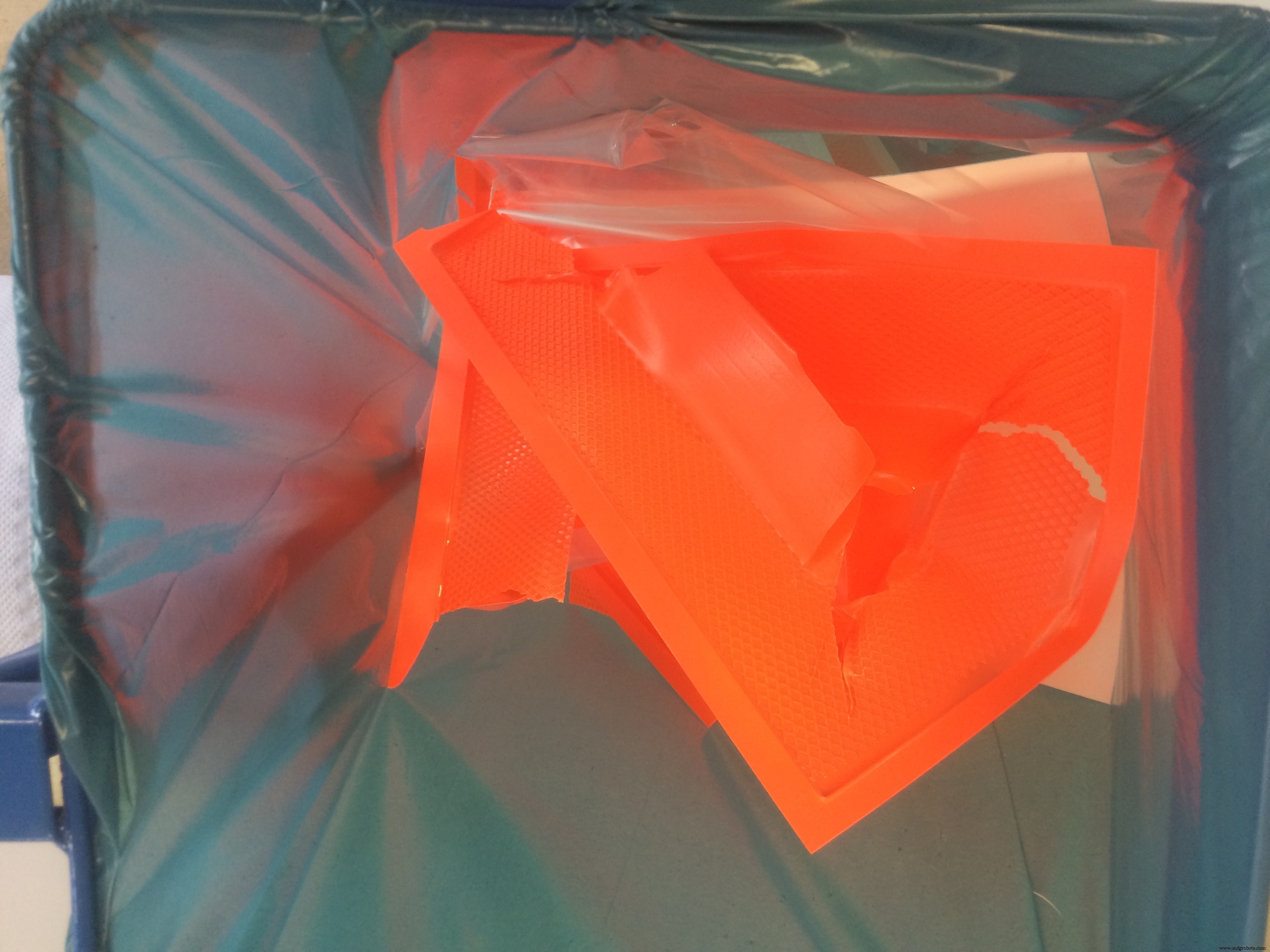
Revisé varios tutoriales antes y aprendí que primero tengo que germinar las semillas. Conseguí un recipiente de plástico, donde coloqué las semillas y las cubrí con una toalla de papel. En esta etapa, necesitan casi el 100% de humedad, por eso utilicé un spray para regar las toallas de papel, y cubrí el recipiente con la bolsa de plástico, para que el agua no se evapore.
Dejé las semillas durante 1,5 semanas y cuando abrí el recipiente, ¡me sorprendí mucho!
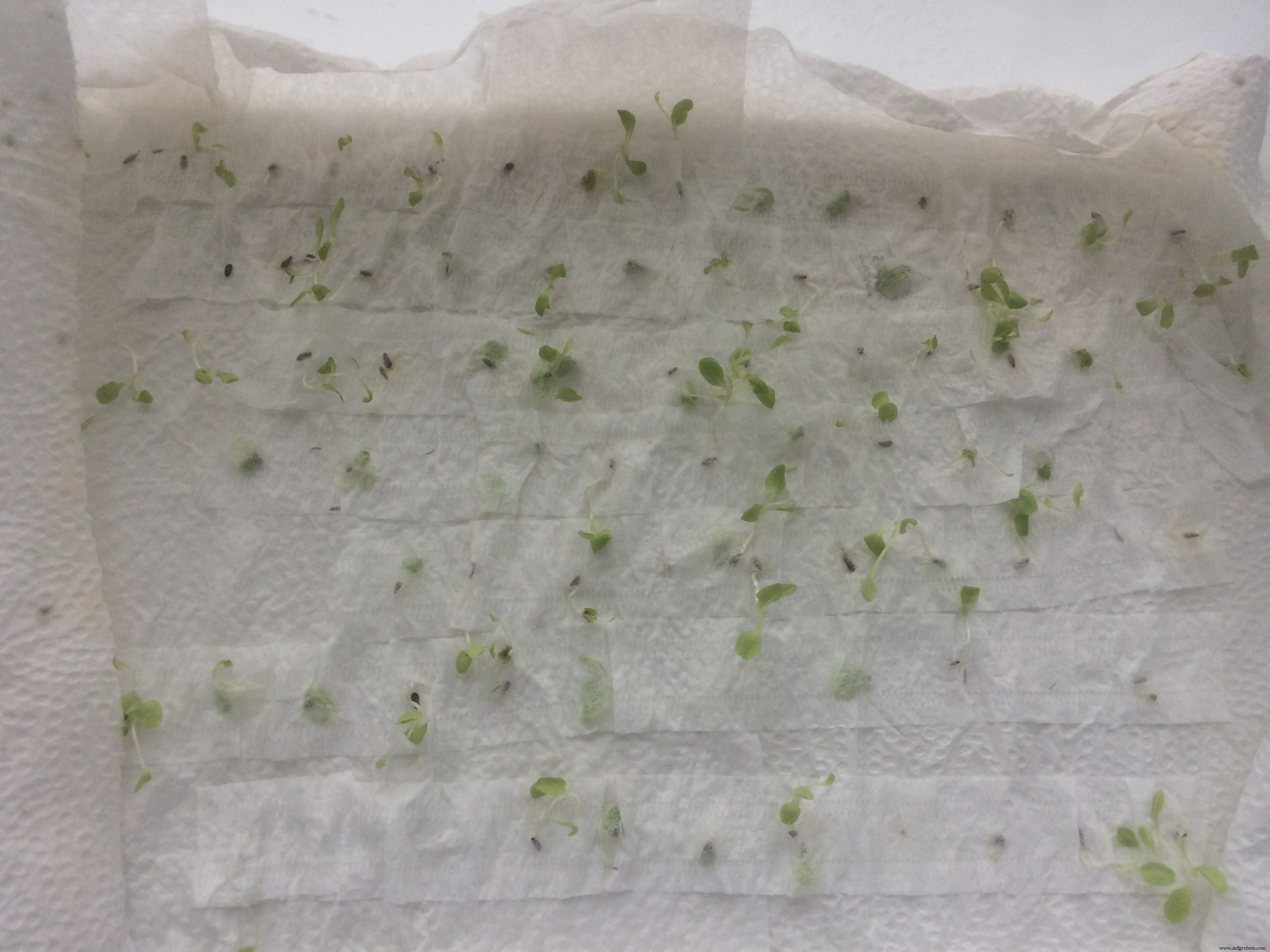
¡Casi todas las semillas germinaron! Era feliz como un niño)
A continuación, tuve que seleccionar las mejores plantas pequeñas, las que tenían el tallo más grueso y se veían más grandes y mejores en general.
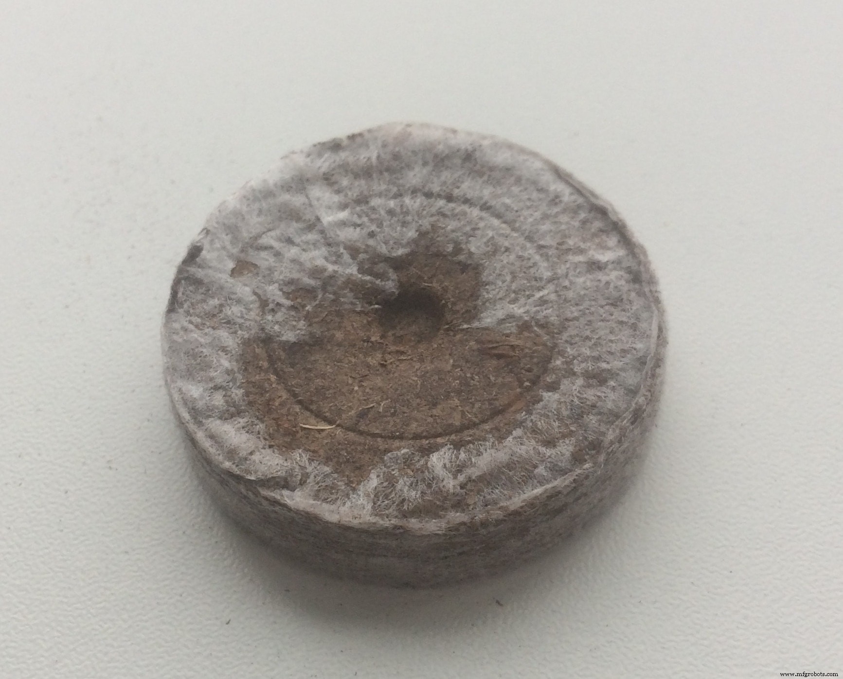
En el tutorial que estaba siguiendo (blogger de YouTube), el chico recomendaba plantar las plantitas en cualquier tipo de medio, hasta que den las llamadas "segundas hojas". En Amazon pedí gránulos de fibra de coco . Son orgánicos, tienen propiedades similares al suelo, y lo bueno es que cuando se riegan los gránulos, se vuelven x6 veces más grandes.
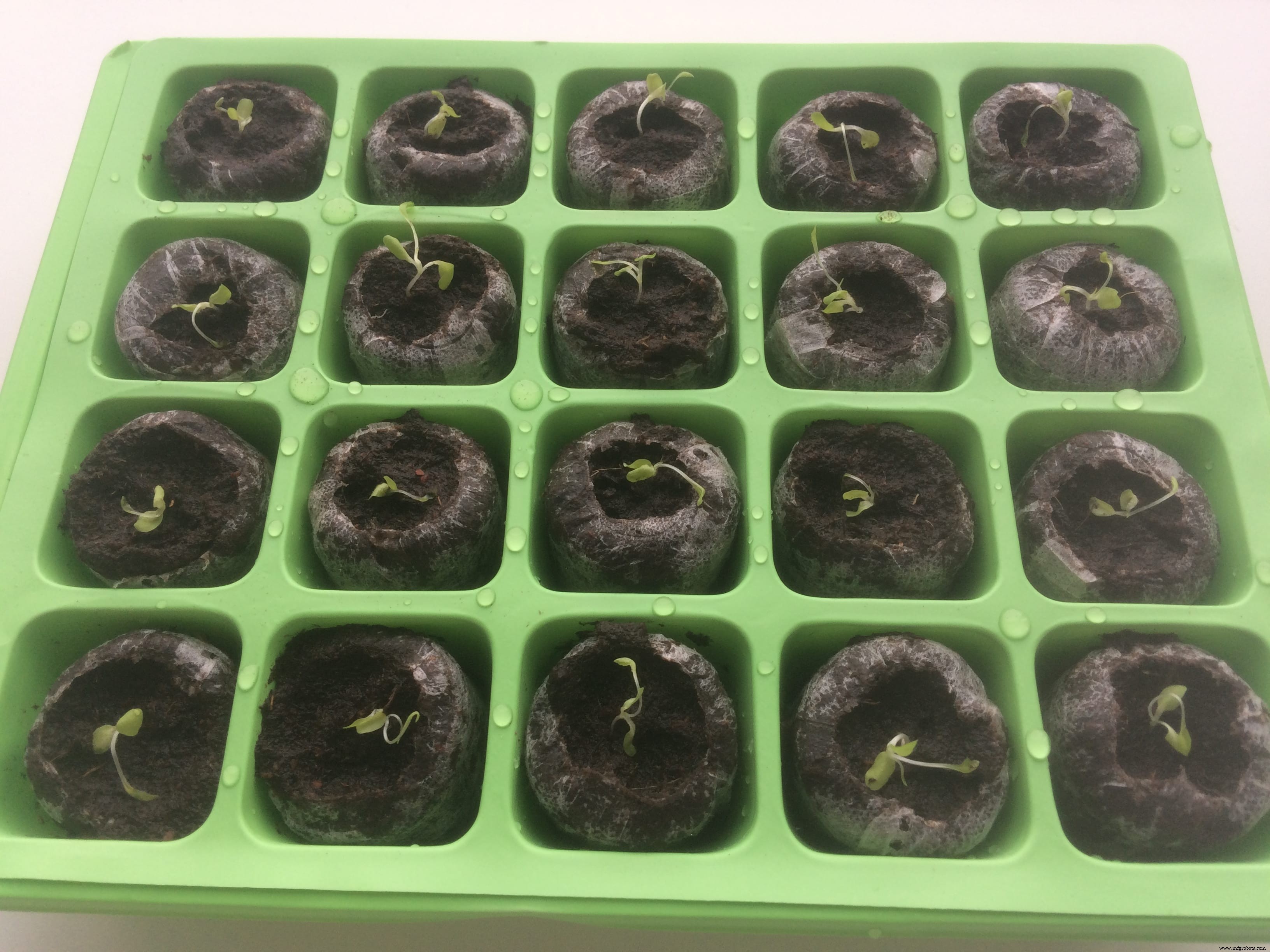
¡También compré una caja, que tiene separadores especialmente para plantar! Lo compré por solo 2 euros, y esto hizo que las cosas estuvieran mucho más organizadas. Coloqué las bolitas de coco dentro de los separadores de la caja, las regué hasta que se hidrataron por completo, coloqué las plantitas en el medio y cubrí la caja con una pieza de plástico transparente que venía con el kit de la caja.
Mi pequeño invernadero se veía así:
¡Cerré la caja y la dejé durante una semana!
Y de nuevo, cuando lo abrí, ¡me sorprendió! ¡De hecho se hicieron más grandes! Nunca me imaginé que podría lograr cultivar algunas plantas, apenas logro cuidarme:D
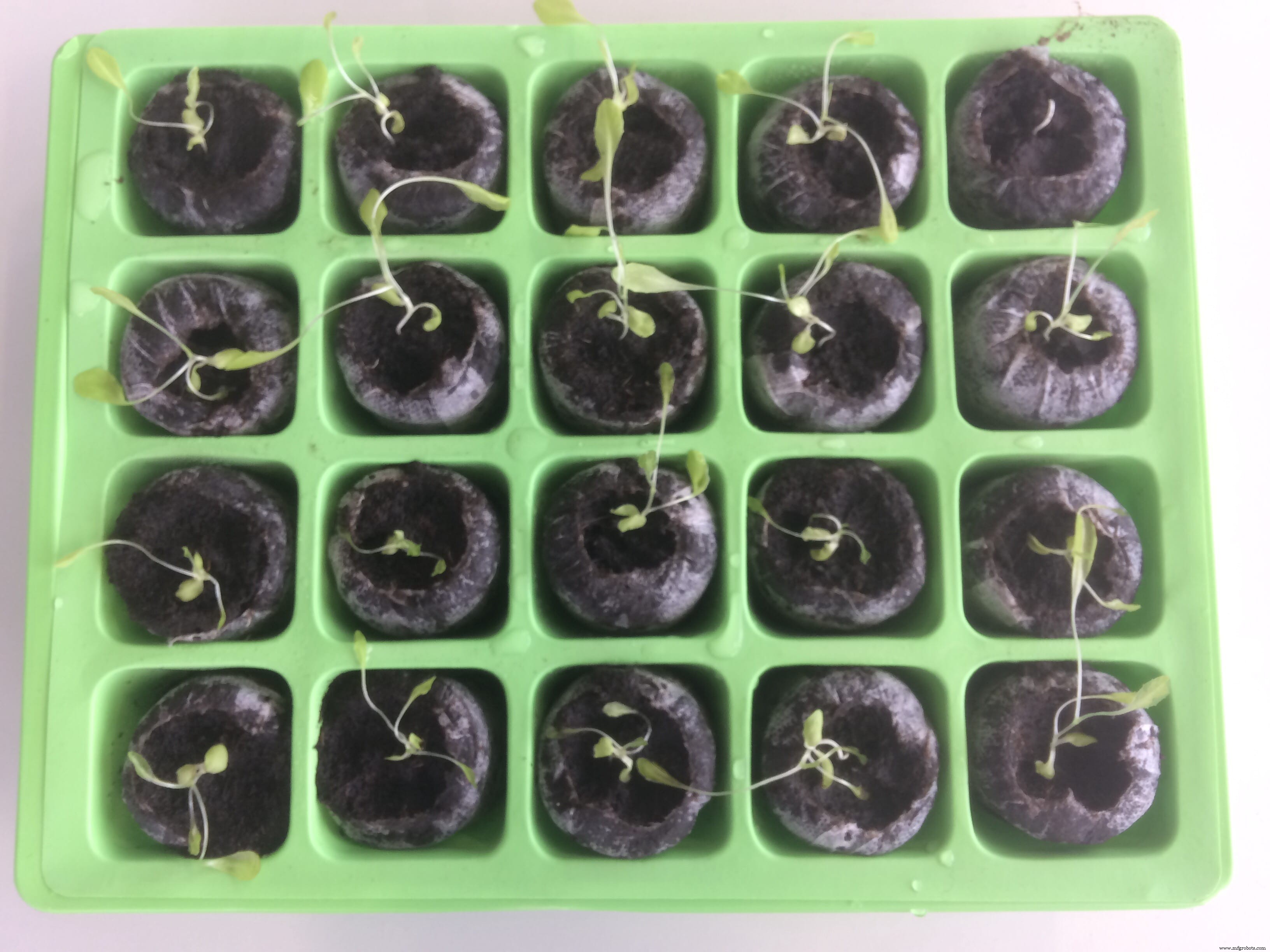
¡Después de una semana, la diferencia es notable!
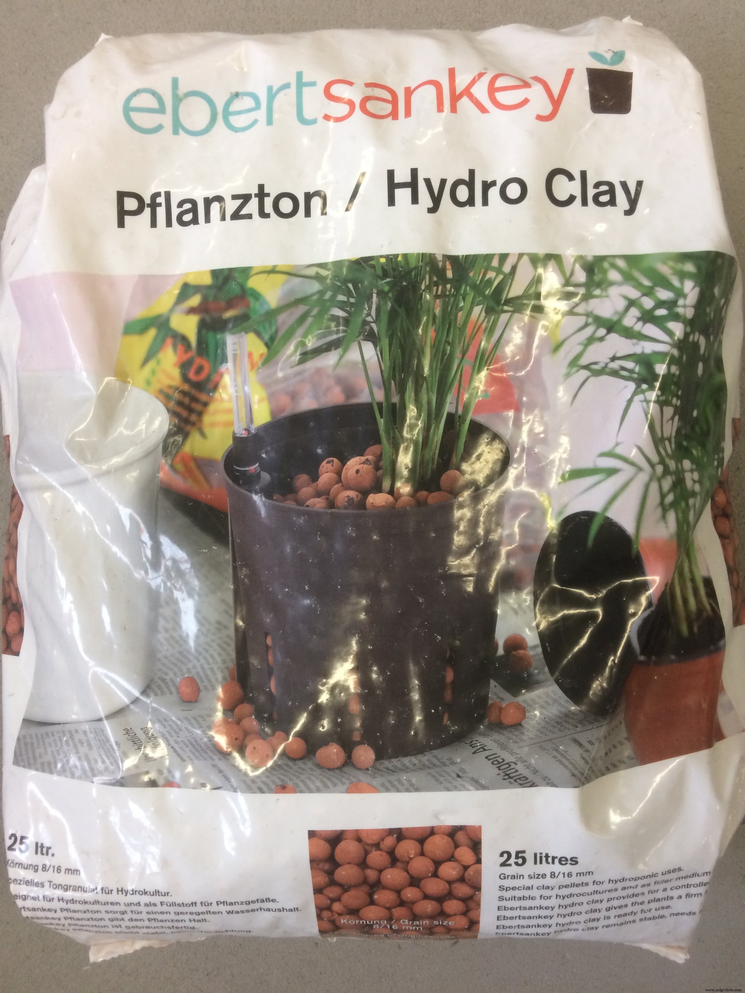
Ahora, cuando veo las primeras raíces, puedo colocarlas en bolas de tierra y arcilla, ¡y comenzar a experimentar con la niebla!
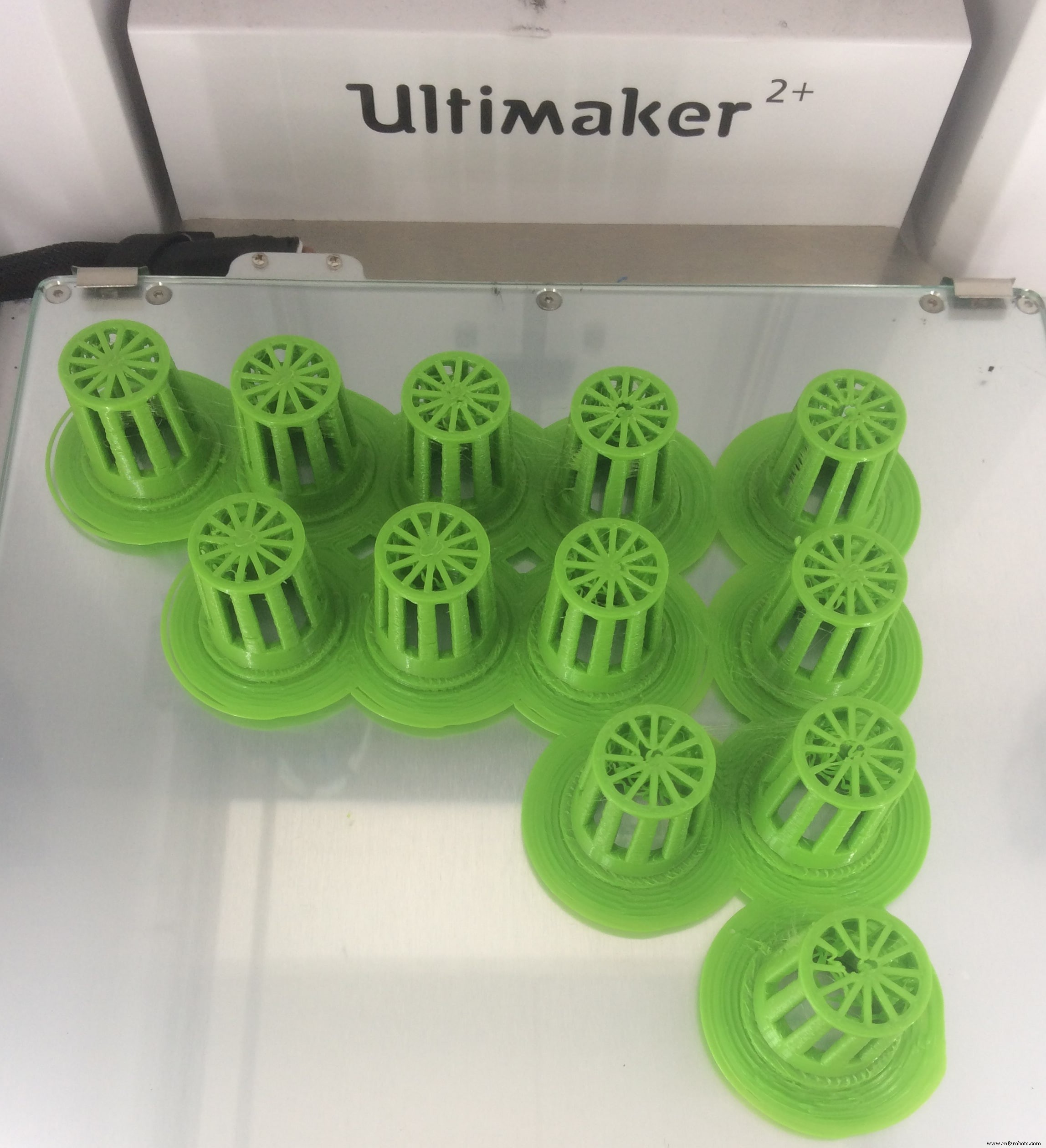
Durante la semana del Diseño Asistido por Computadora, diseñé los vasos de red, que usé para colocar las plantas
También compré en una tienda local un recipiente de plástico con las dimensiones aproximadas que necesito, ¡y dibujé los agujeros para perforar!
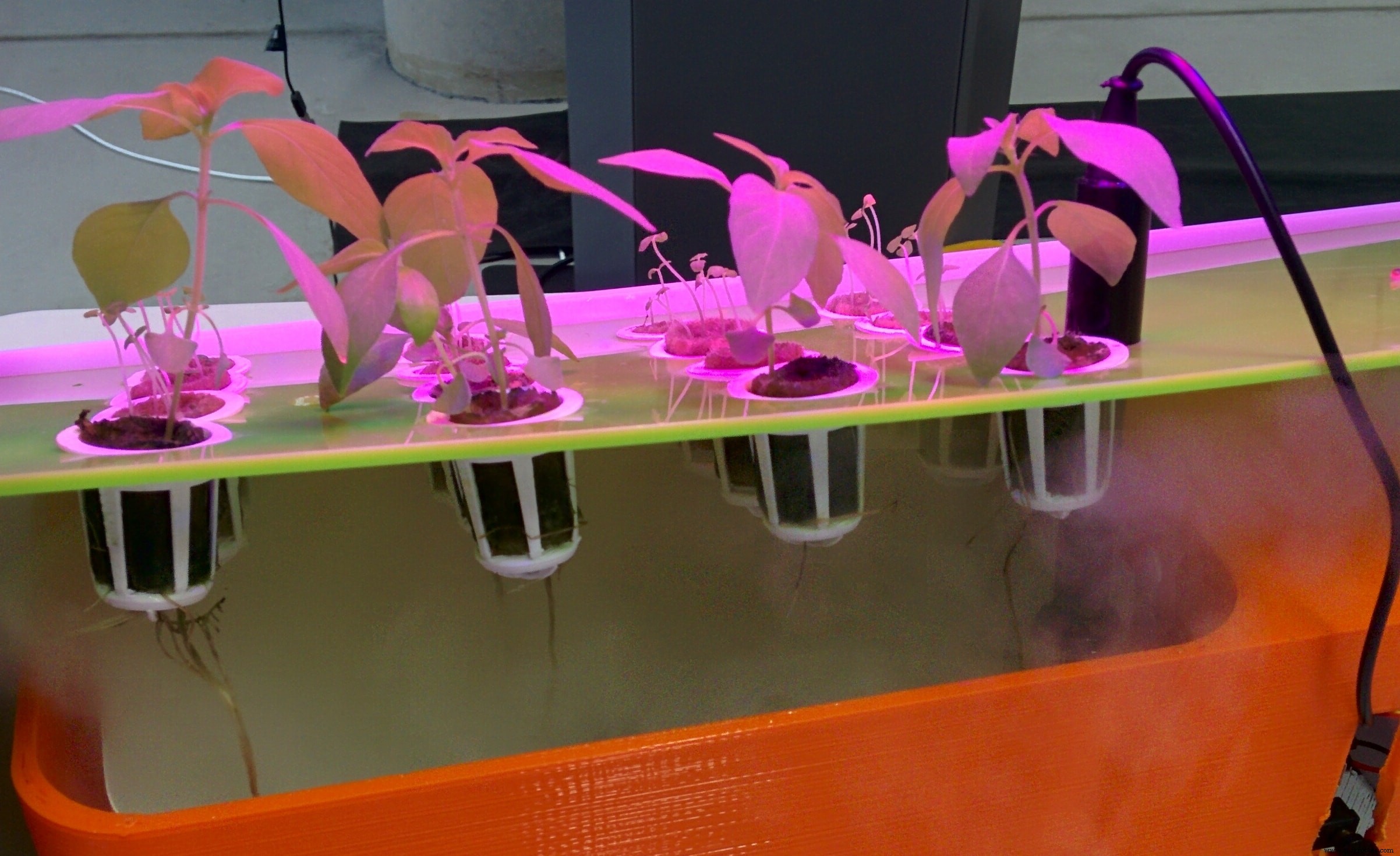
¡Y aquí está mi sistema de prueba ensamblado, con las plantas dentro de las bolitas de coco y las bolas de arcilla, así como la tierra!
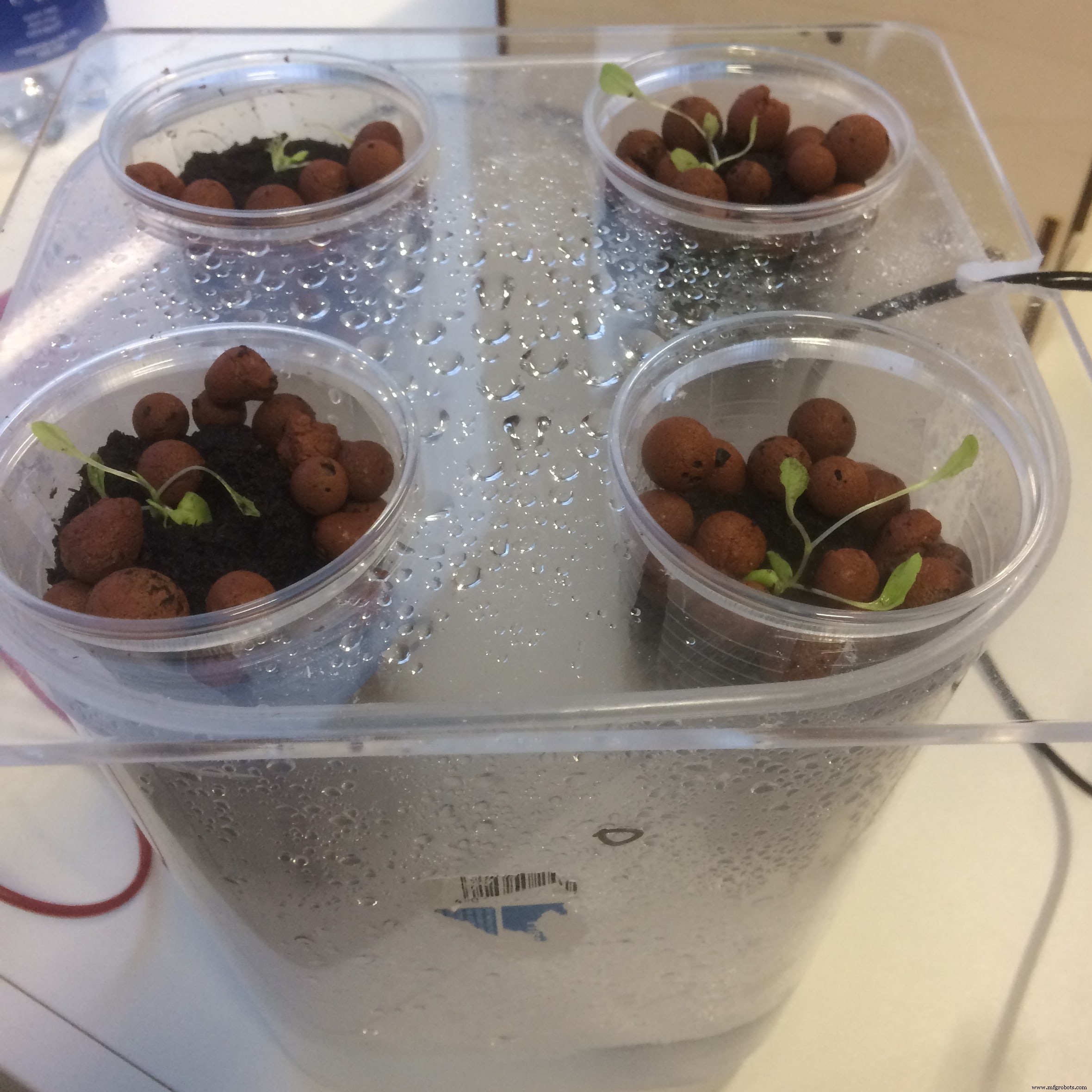
Para ser honesto, los resultados podrían ser mejores:D
Solo unas pocas plantas sobrevivieron en mi sistema de niebla. ¡Mi conjetura es por el medio de cultivo! La niebla no es lo suficientemente fuerte como para mantener húmedas las bolas de arcilla, ni el suelo.
¡Vacaciones de Pascua!
Durante el receso de Semana Santa no hice nada, y como el laboratorio estaba cerrado, todo el sistema también estaba apagado. Entonces, todas mis plantas murieron
Con la mente fresca, decidí hacer otro sistema, pero esta vez usando otro medio de cultivo basado en las observaciones anteriores
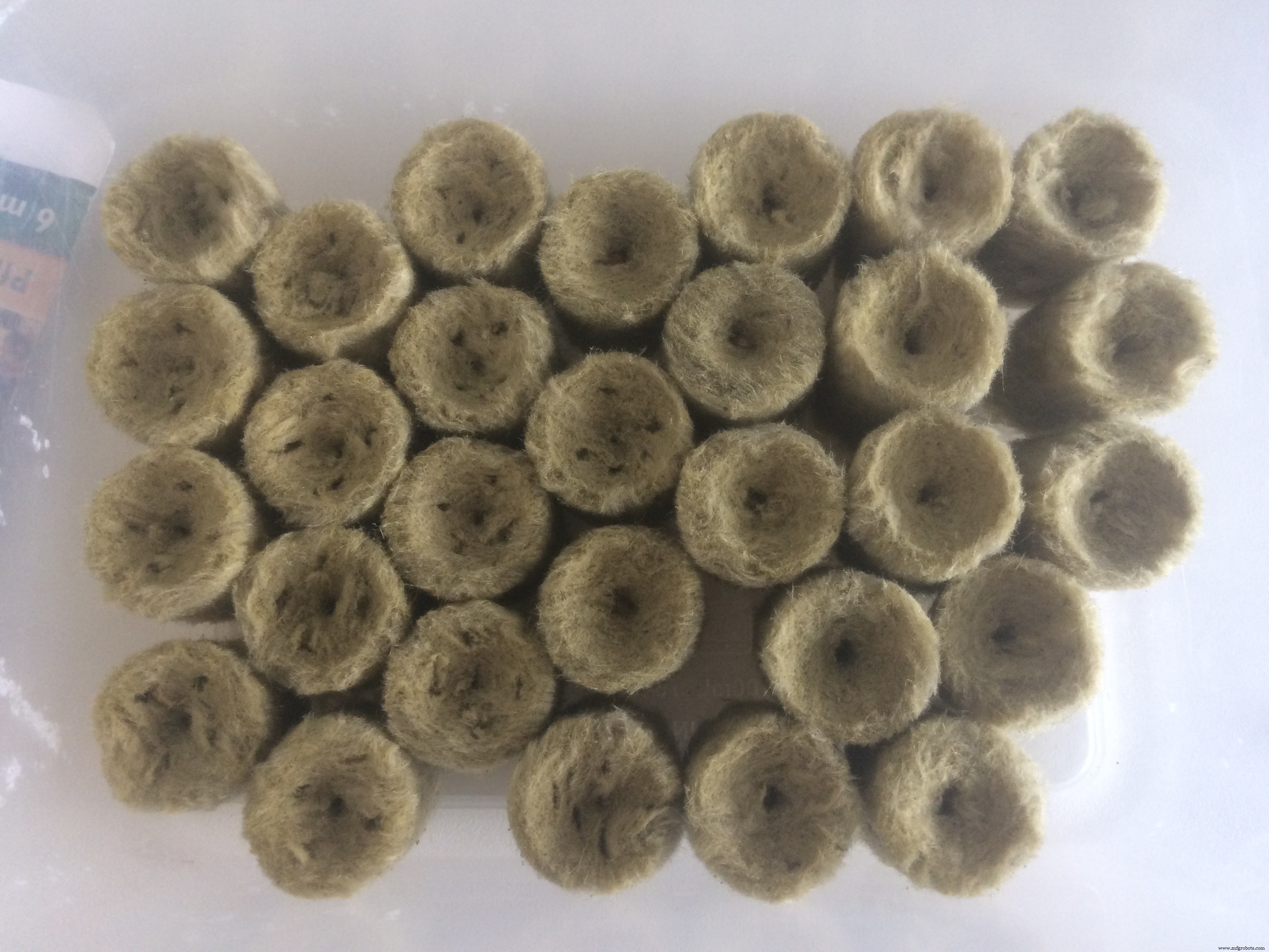
El medio de cultivo que elegí para este sistema es lana de roca . Lo compré en nuestra tienda IKEA local. También compré un par de semillas en su departamento

¡Y coloqué las semillas nuevas en la lana de roca para que germinen durante una semana!
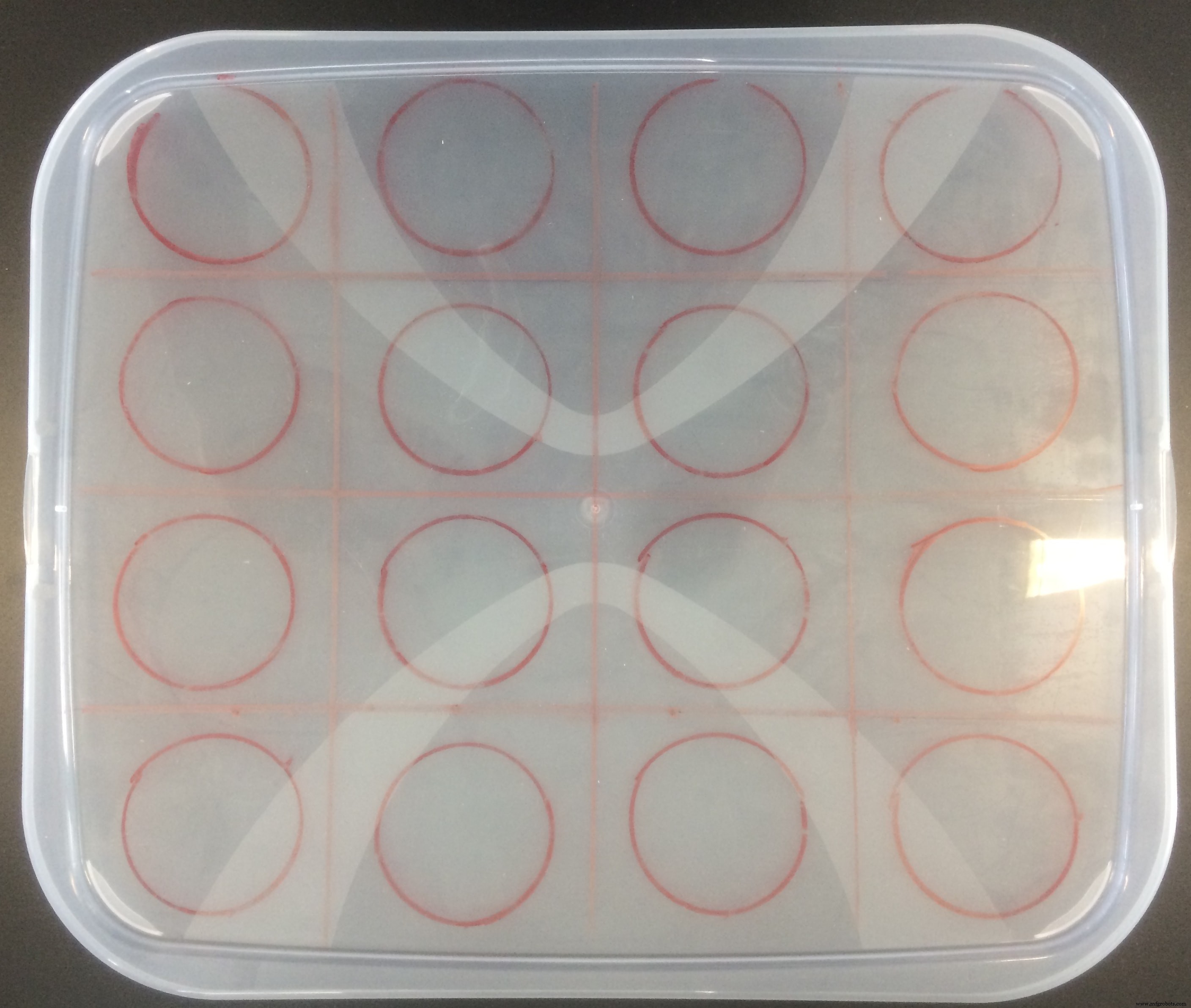
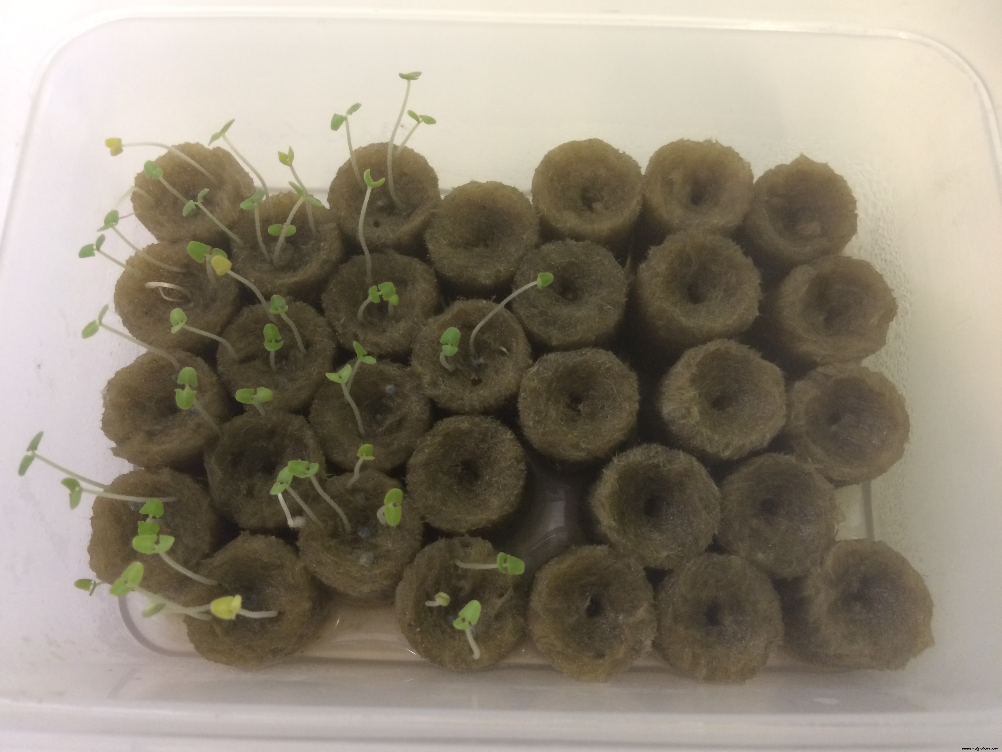
Después de una semana, marqué mi casilla y me di cuenta de que un tipo de semillas tuvo éxito, ¡otro falló! Por falta de tiempo seguí con las semillas que germinaron
Mientras tanto, configuro otro sistema de niebla e intentaré aumentar su tiempo de trabajo para ver si puedo germinar semillas usando niebla, ¡SOLO NIEBLA!
Seguiré experimentando con diferentes parámetros y configuraciones, ¡y veré hasta dónde puedo llegar!)
Diseño y producción de electrónica
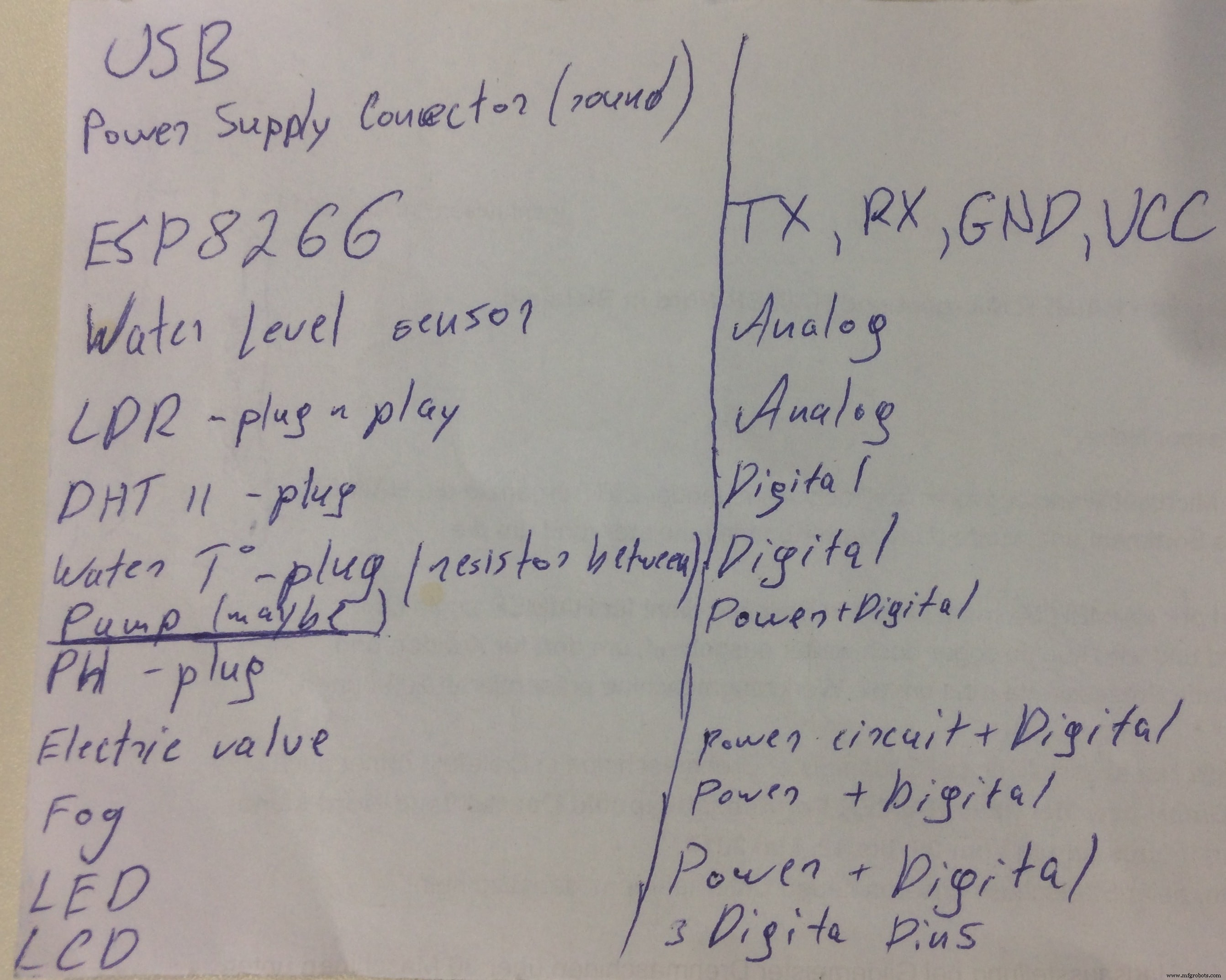
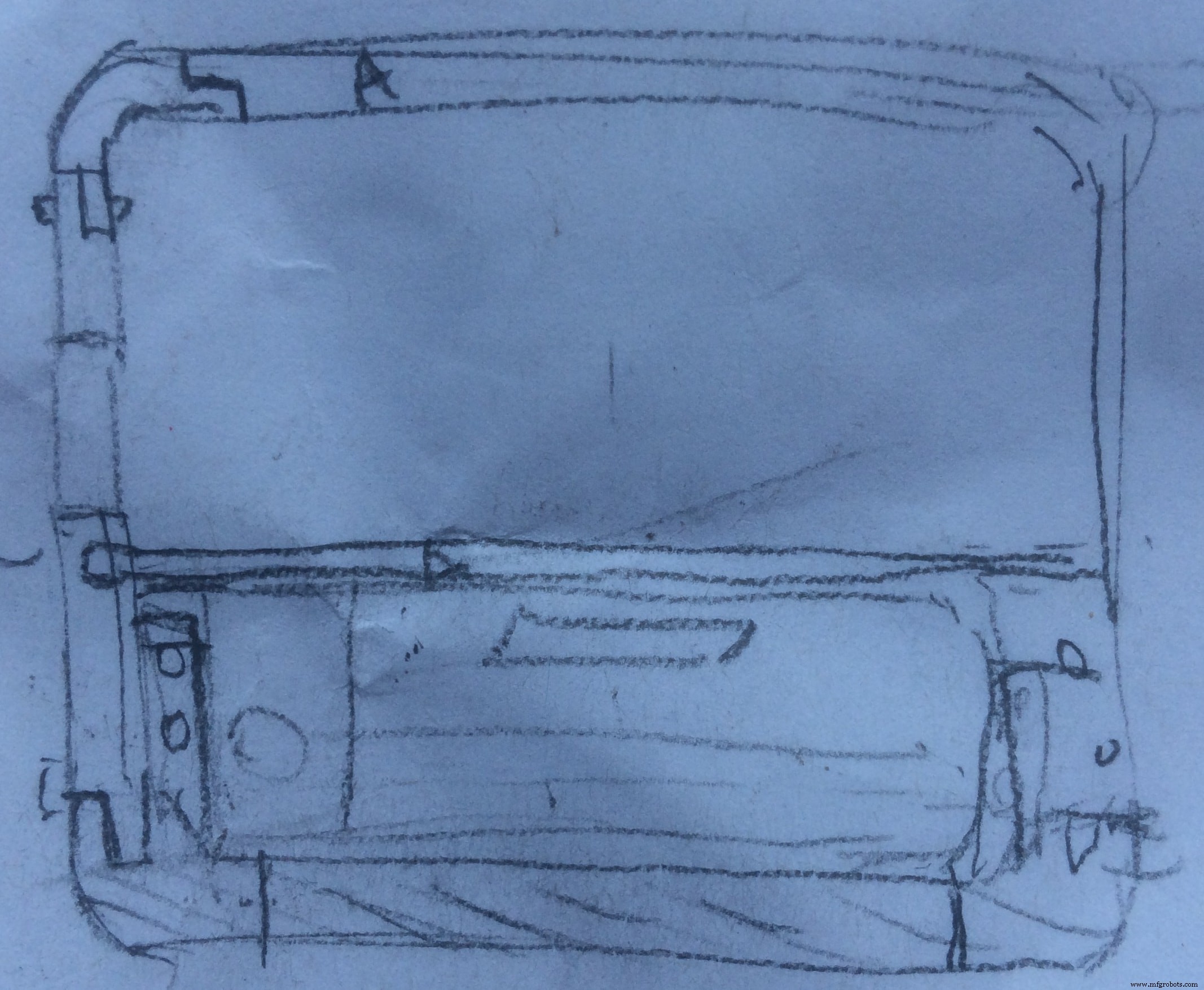
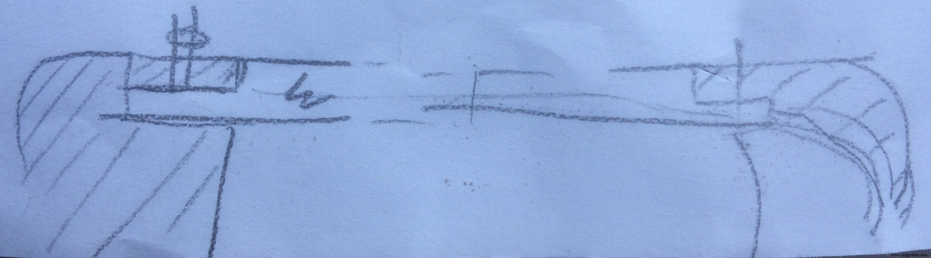
Antes de lanzarme al diseño del tablero final, me senté a dibujar en un papel todas las características y requisitos que el tablero debe implementar y cumplir. También hago un seguimiento de cuántos pines se van a utilizar, con el fin de estimar mejor y decidir cuál será el microprocesador final
Aquí está el boceto de lo que debería estar en la pizarra:
La elección final de qué tablero usar fue entre satshakit de Daniele Ingrassia y FABLEO por Jonathan Grinham
satshakit es un IDE 100% Arduino y compatible con bibliotecas, fabbable y placa de código abierto, y también una versión mejorada de Fabkit.
Las principales mejoras y características de Fabkit son:
- 16 Mhz en lugar de 8 Mhz
- cristal en lugar de resonador
- cuesta menos (7-9 euros frente a 13 euros)
- 100% compatible con Arduino IDE predeterminado (satshakit se reconoce como Arduino UNO)
- ADC6 / 7 conectado en lugar de ADC6 / 7 no conectado (satshakit láser y cnc)
- espacio más grande para facilitar la soldadura (satshakit láser y cnc)
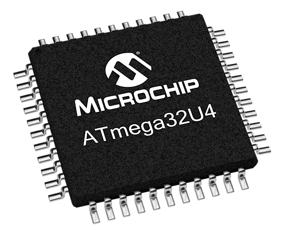
Por otro lado, FabLeo tiene características muy similares, ¡además del hardware USB! Como ya usé el ATmega328p antes, quería probar algo nuevo y decidí usar el diseño de FabLeo como mi punto de partida
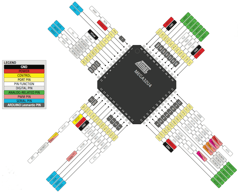
Mi biblia y la guía n. ° 1 para esta tarea fue el pinout ATmega32u4
Para diseñar la placa, el software que usaré para esto es EAGLE (Editor de diseño gráfico de fácil aplicación) es un programa de captura de esquemas EDA, diseño de PCB, enrutador automático y CAM flexible y expandible. EAGLE es popular entre los aficionados debido a su licencia de software gratuito y la gran disponibilidad de bibliotecas de componentes en la web.
Eagle tiene dos ventanas que se utilizan simultáneamente para diseñar un tablero:
- Esquema (.sch) - componentes lógicos
- Diseño de la placa (.brd) para el tablero real que fresamos
Después de instalar EAGLE, lo primero que quiero hacer es Crear un nuevo esquema . Un esquema en electrónica es un dibujo que representa un circuito. Utiliza símbolos para representar componentes electrónicos del mundo real. El símbolo más básico es un conductor simple (trazos), que se muestra simplemente como una línea. Si los cables se conectan en un diagrama, se muestran con un punto en la intersección.
Para colocar mis componentes en los esquemas, tengo que descargar y utilizar Bibliotecas especiales . Eagle tiene muchas bibliotecas de componentes integradas que podemos usar. La red fabulosa también mantiene una biblioteca que se actualiza constantemente:
fab.lbr
Para instalar la biblioteca, en el entorno EAGLE, vaya a la barra de herramientas superior y seleccione Library menú. Luego seleccione usar y abra el .lbr archivo que acabo de descargar.
Ahora puedo ir a Agregar componente y seleccionando la biblioteca, elijo el componente que quiero colocar.
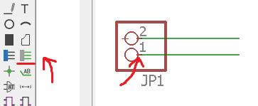
Cuando tengo todos los componentes colocados en mis esquemas, tengo que conectar cada uno de ellos a los pines del microprocesador. En el menú de la izquierda de EAGLE, hago clic en Net , comando que me permite dibujar líneas verdes y conectar los pines. Lo importante es iniciar la conexión desde la pequeña línea del pin (lo marqué en la imagen)
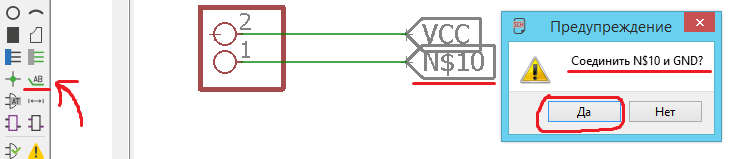
Para evitar múltiples conexiones, utilizaré Etiquetas. . En el menú izquierdo de EAGLE, presiono Agregar etiqueta y agréguelo al final de mi línea de conexión. Si presiono el clic derecho y luego elija nombre , Puedo atribuir a la etiqueta el mismo nombre que usé para el pin del microprocesador, ¡y conectarlos de esta manera!
Si hice todo bien, debería aparecer un mensaje que diga: ¿Está seguro de que desea conectar su etiqueta (N $ 10) con GND?
En esta etapa, en la química, lo importante es la Lógica de todas las conexiones, no como se ve. Una vez que terminé de colocar todos los componentes y los conecté de una manera lógica, así es como se ve:
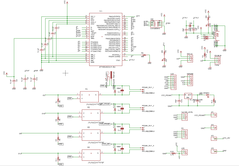
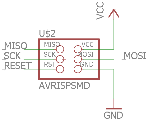
Agregué el AVRISP cabezales de alfiler y colocarlos en el orden del conector. Estos pines se utilizarán para programar mi placa.
Aquí están los esquemas del USB circuito junto con el cristal
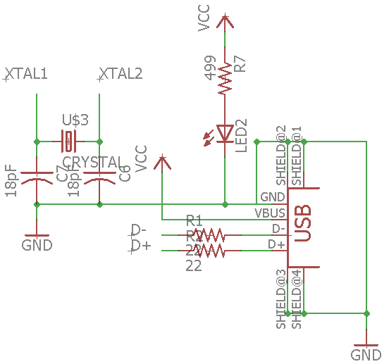
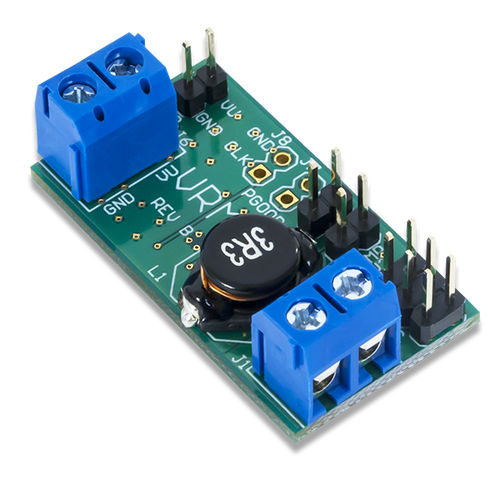
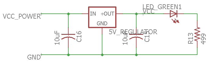
También agregué un regulador de voltaje circuito que alimentará toda la placa transformando la entrada 12V en 5V
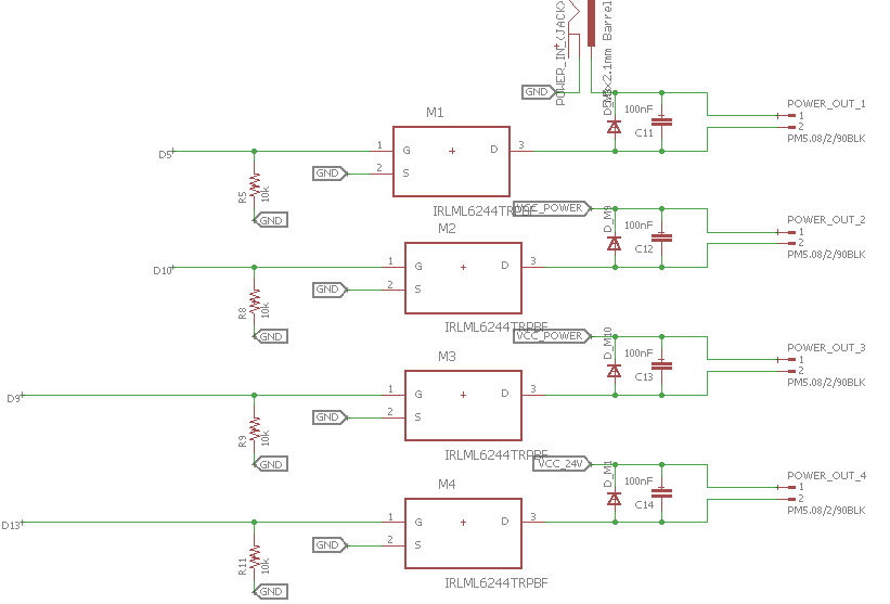
Una de las características importantes de esta placa es el MOSFET circuitos, agregué 4 de ellos, 3 conectados directamente a la entrada (12V), y uno se conectará a un regulador de voltaje elevador. El último se utilizará para alimentar la niebla que funciona a 24 V
Después de verificar todas las conexiones, puedo continuar con el siguiente paso, que es el Diseño de la placa . . En el menú superior, presiono Generate / Switch to Board .
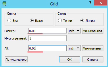
Lo primero que hago es aumentar la cuadrícula resolución. Voy a Ver menú y presione Grid y cambie los valores a 0.01 . Esto me permitirá ser más preciso al dibujar las líneas de ruta.
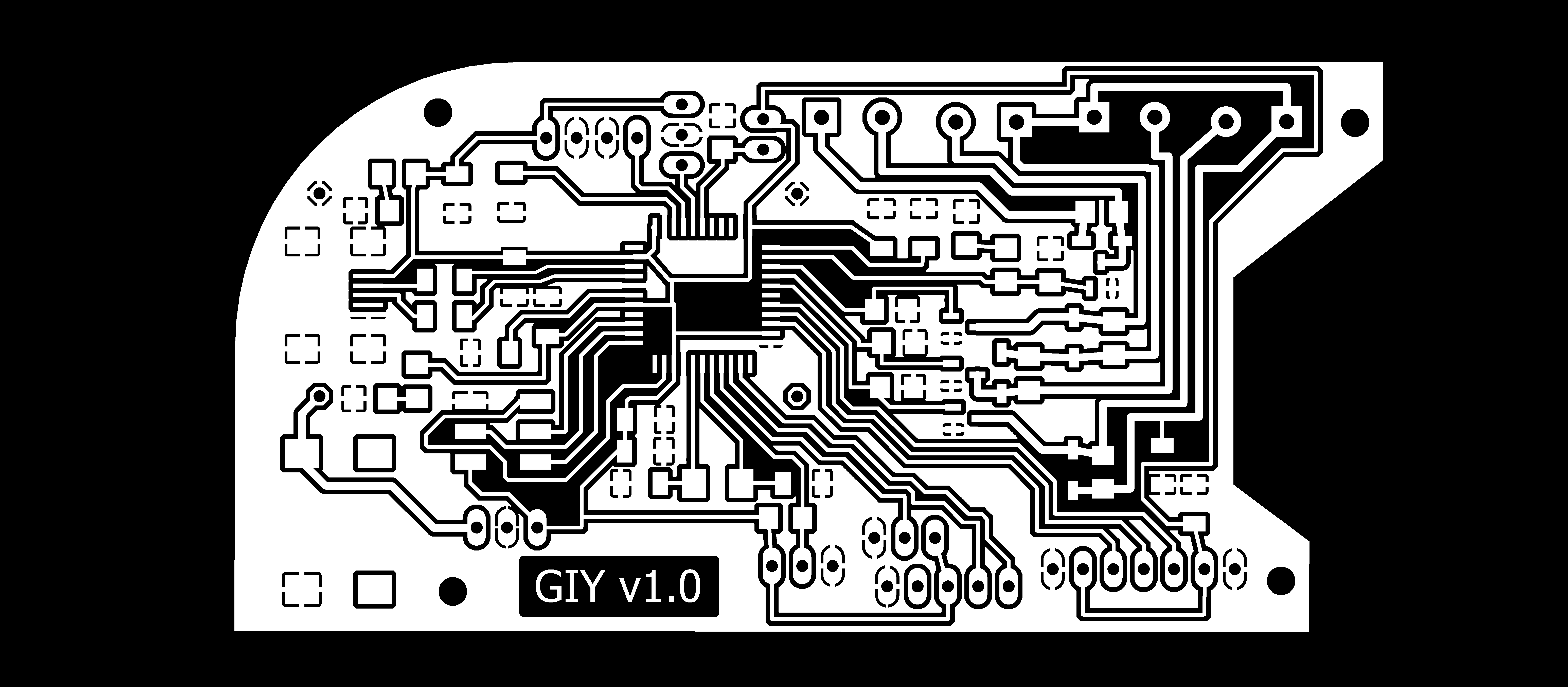
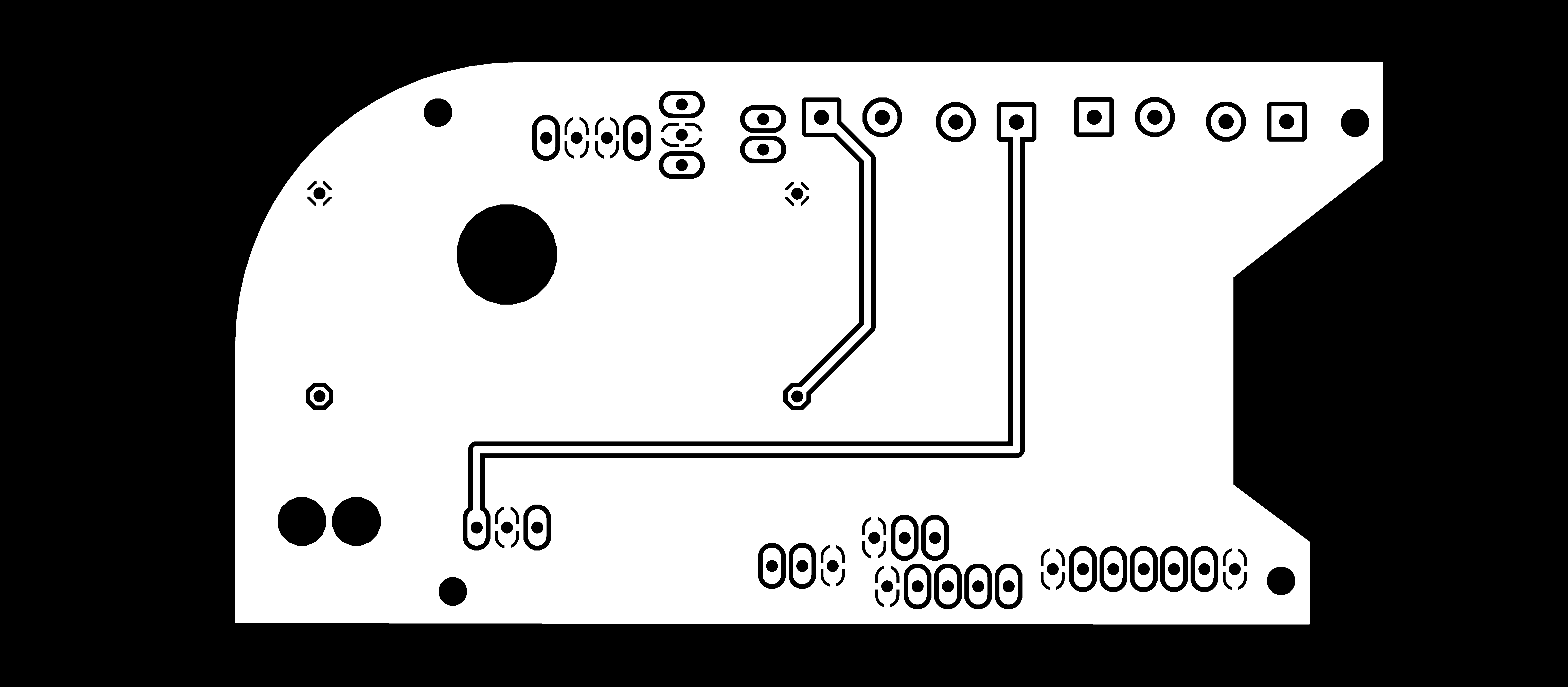
¡Sorprendentemente, el enrutamiento de la tabla más compleja que he hecho hasta ahora también fue el más rápido!) Estoy orgulloso de mí mismo. La experiencia de hacer tablas influyó positivamente en la mejora de la velocidad. Una vez que terminé de enrutar, así es como se ve la pequeña bestia:
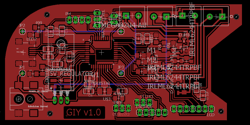
Para esta placa también estoy usando el truco que aprendí antes. Dibujo un polígono alrededor de mis componentes y, al presionar el clic derecho en la línea del polígono, cambio el nombre a GND. Esto llenará toda el área dentro del polígono y lo convertirá en GND.
Esto ahorrará mucho tiempo, espacio y esfuerzo
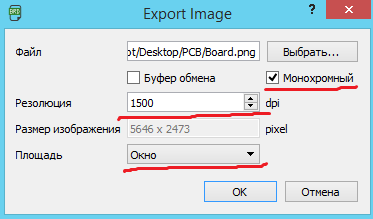
Cuando verifico todo, puedo Exportar mi archivo como .png imagen.
En la ventana que aparece, aumento la resolución a 1500 dpi , haga clic en monocromo y seleccione ventana modo.
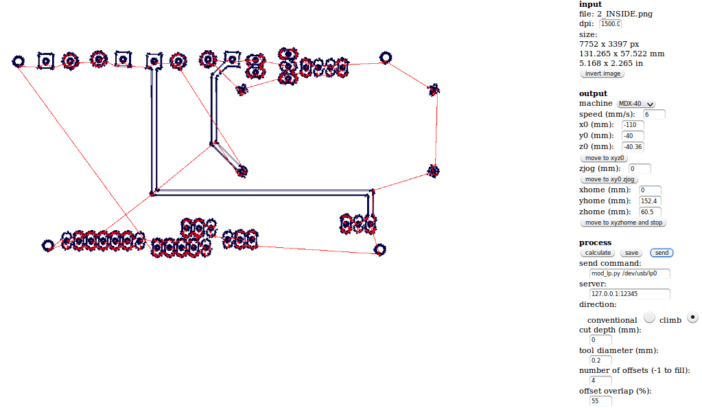
Para editar la imagen.png, usaré Abro mi imagen en GIMP , y usando la herramienta de selección rectangular , Selecciono la imagen dejando algo de espacio por todos los lados. Después de presionar Archivo y Copiar el área seleccionada. Para seguir trabajando con la imagen seleccionada, vuelvo a hacer clic en Archivo y Crear desde el portapapeles
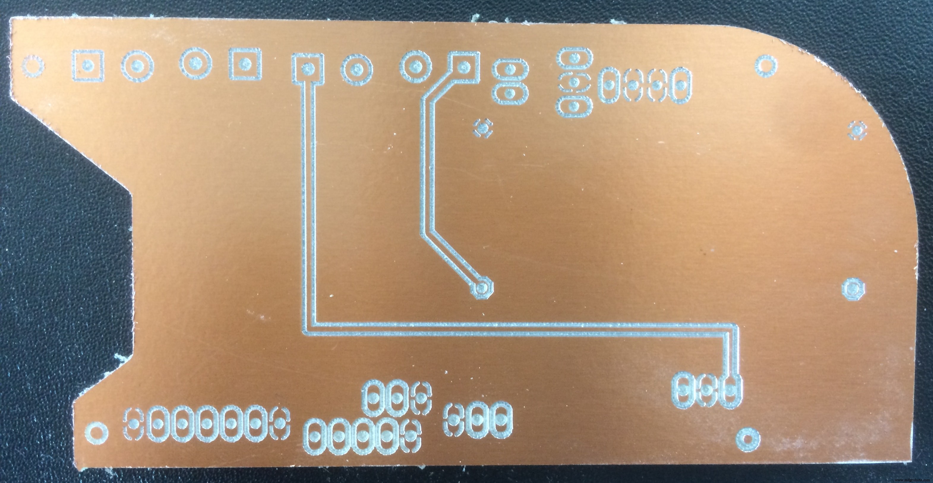
Esto es lo que obtengo después de todas las ediciones:
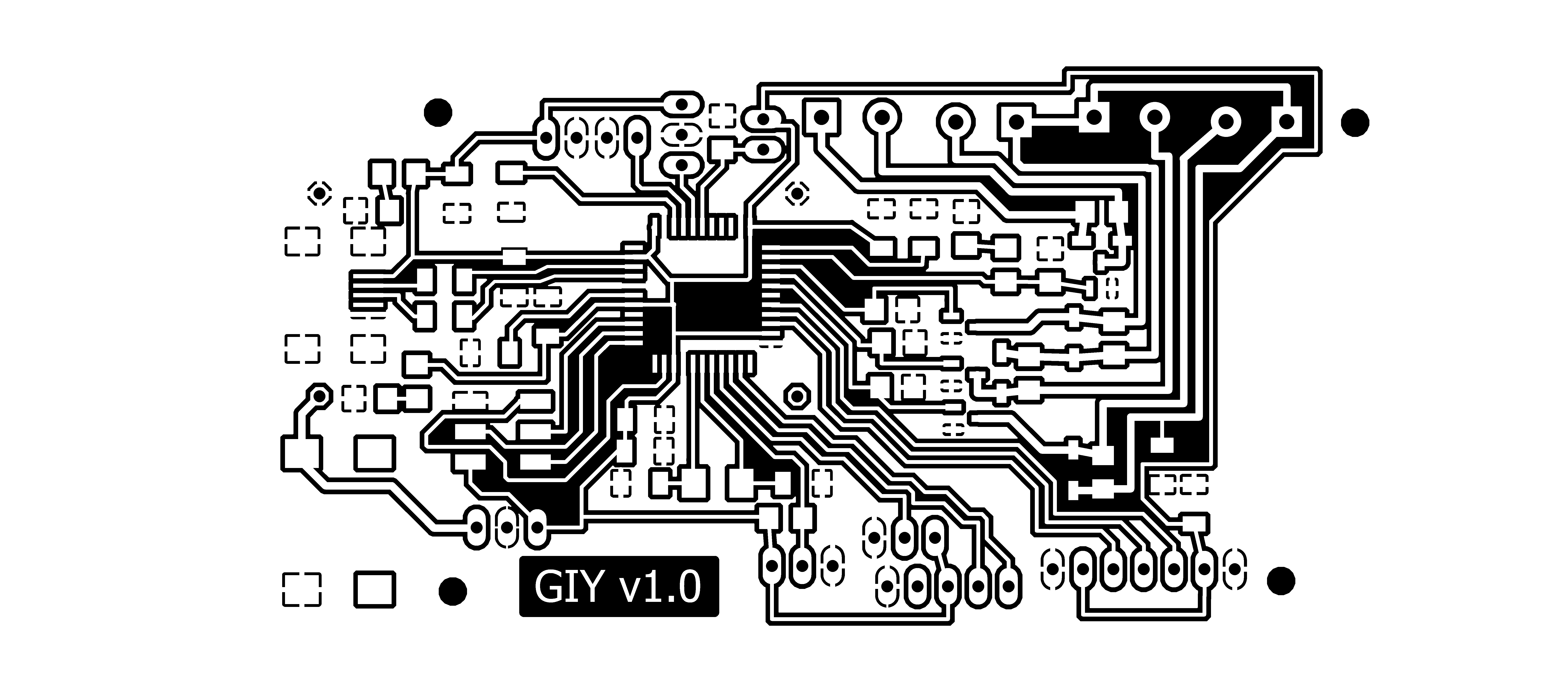
Esta imagen está lista para imprimirse y la llamaré Inside_Cut
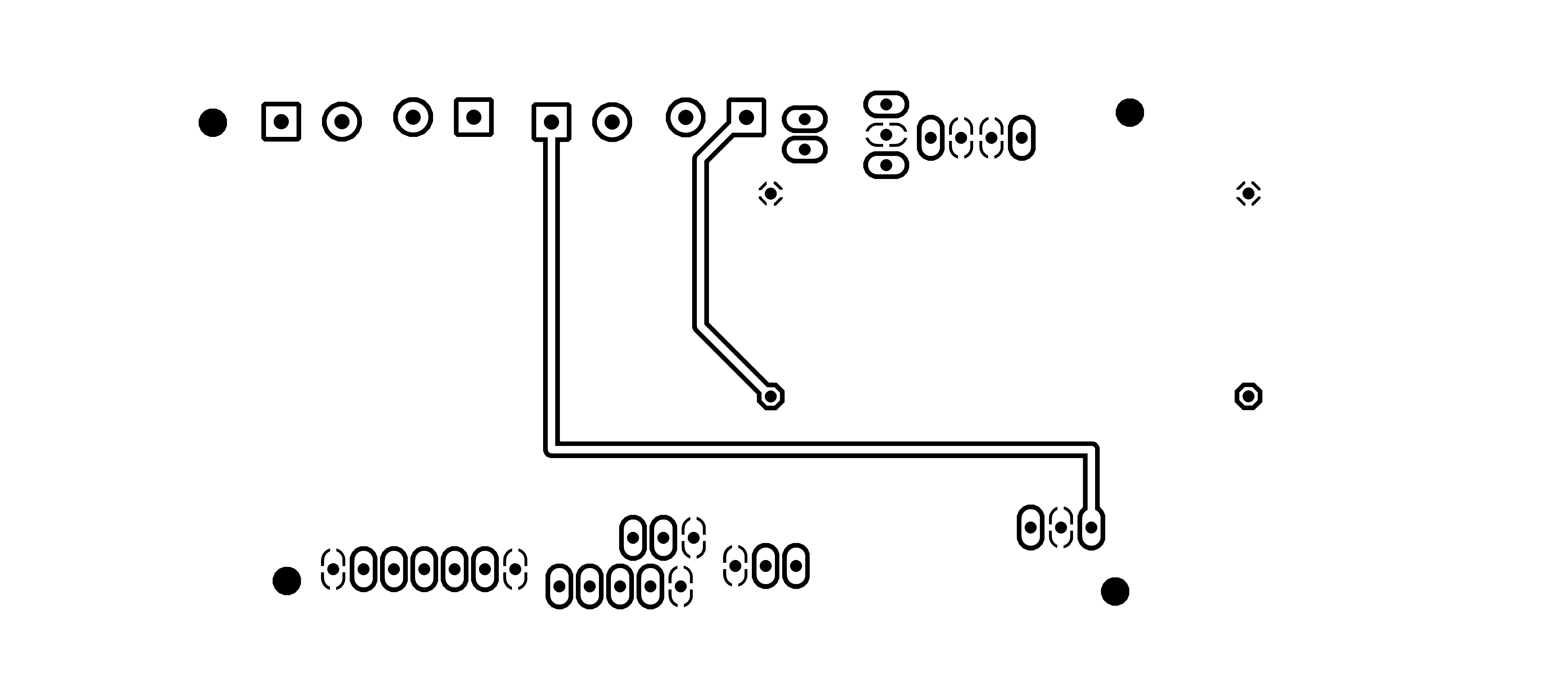
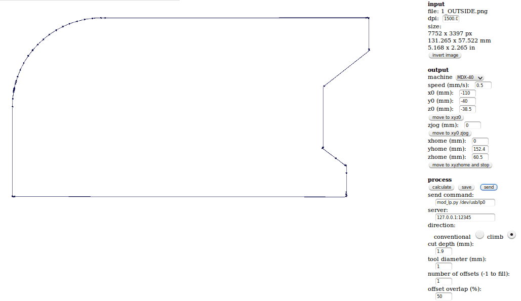
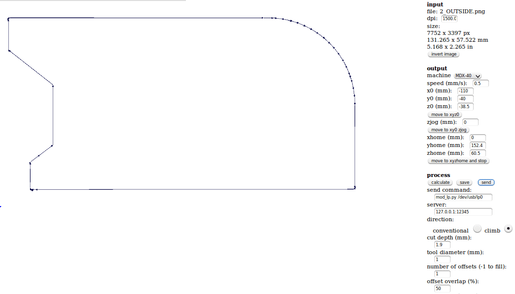
Preparo el proceso para el Corte exterior , y esto es lo que obtengo:

Debido a que mi tablero es de doble cara, tengo que fresar dos piezas y luego pegarlas. Lo único a tener en cuenta es que la parte inferior tiene que ser reflejada horizontalmente
Parte inferior Inside_Cut

Parte inferior Outside_Cut
Ahora puedo pasar a la fresadora CNC. Entonces, nuevamente usé FabModules para convertir los archivos .PNG en Gcodes para la máquina Roland.
Empecemos a trabajar con los módulos Fab. Cuando introduzco la dirección IP en la ventana del navegador, la primera interfaz que aparecerá es:
Después de presionar el botón gris formato de entrada , debería aparecer un nuevo menú con la opción de cargar la imagen .PNG. Aquí subo la primera imagen, que es el grabado interior. Después de hacer eso, la vista previa de la imagen aparecerá en los Módulos Fab y también aparecerán otros campos y otros parámetros
En el lado derecho de la ventana, tenemos muchos parámetros de entrada. Para poder mover la máquina, tenemos que ingresar los siguientes parámetros:
mod_lp.py / dev / usb / lp0 en el comando enviar campo
hostname_of_your_machine en el servidor field (just the address without http or /)
In order to move the machine I just enter in the respective fields the x, y and z position coordinates. Before moving the machine I have to make sure that the zjog parameter is always set to 0, even if it will change automatically. To move the machine I have to press the move to xyz0 button.
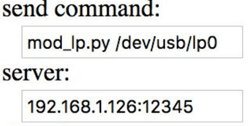
* A small life hack is to use the multimeter and check if there is connection between the tool and the surface. As a tool to engrave PCB is suggested to use diameter from 0.2 mm and below, while for cutting we can use a 1 mm herramienta.
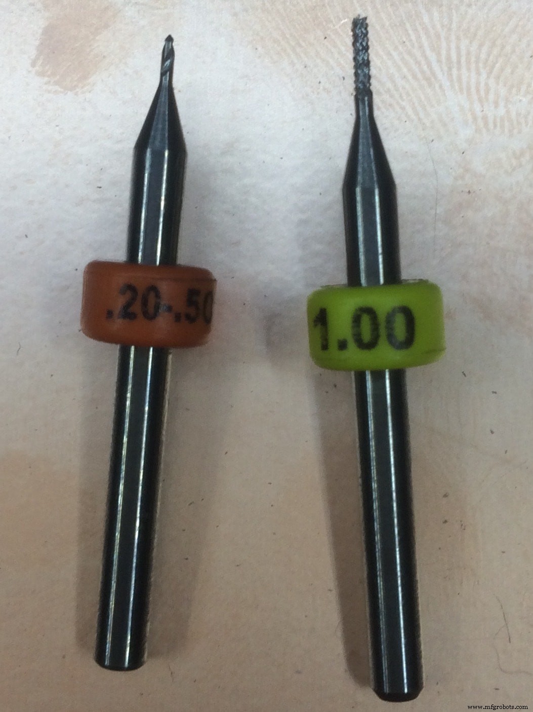
So my final settings look like this:
For the outside cut the settings remain the same with the exception of the value of the Z-Axis, as I replaced the 0.2mm tool with the 1mm tool. This is how it looks:
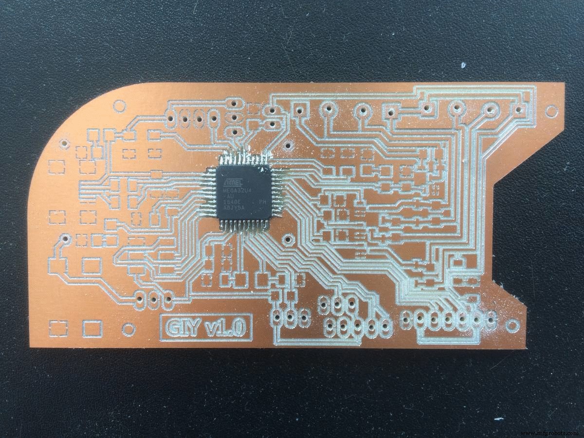
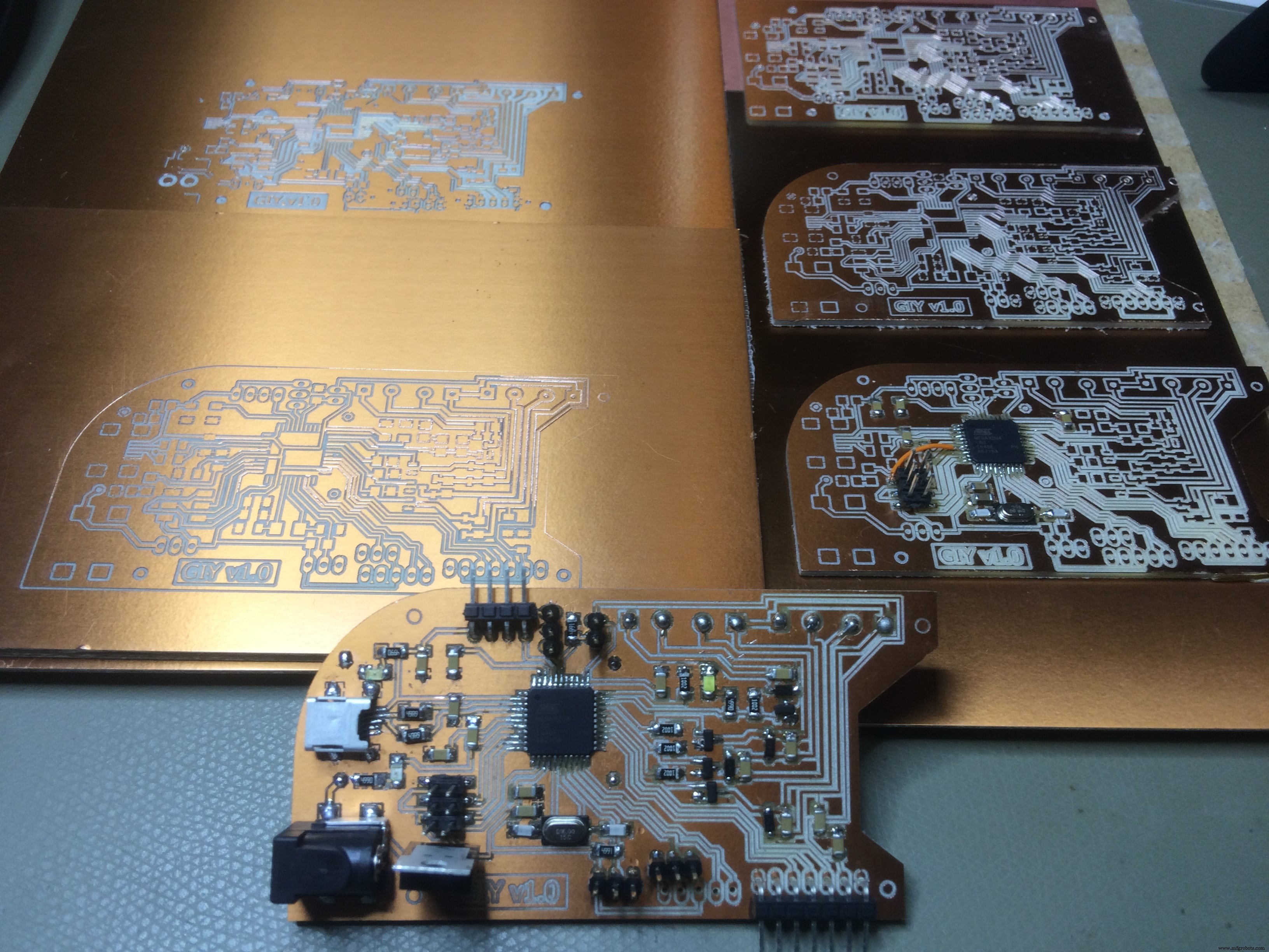
Repeat the same process for the Bottom part and mill the Inside and the Outside parts:
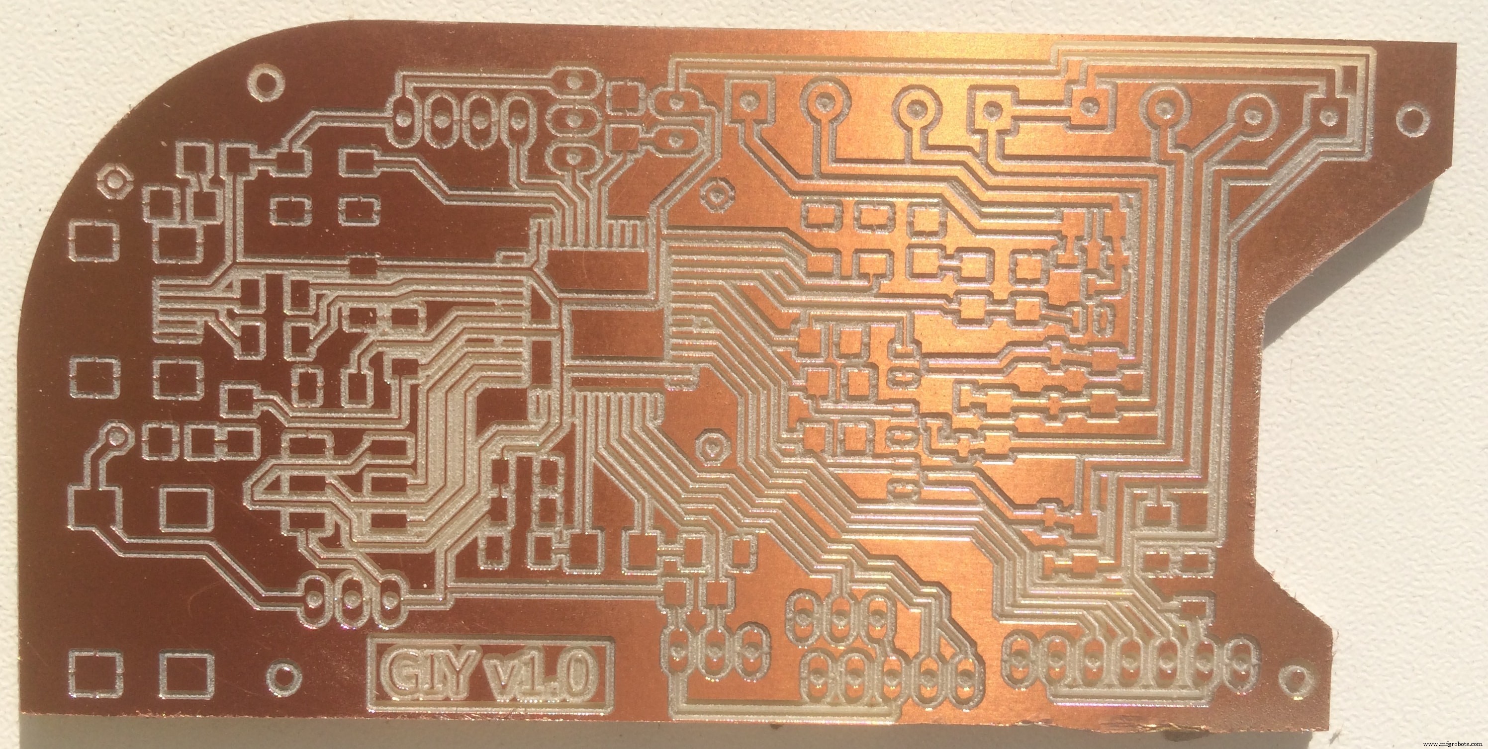
This is the final result for the Top part:
And the Bottom part:
And now Let's solder this!
In order to make sure that I soldered everything in a right way, after each component soldered, I used the multimeter to check if there is conductivity between the component and the traces.
Short animation of the process:
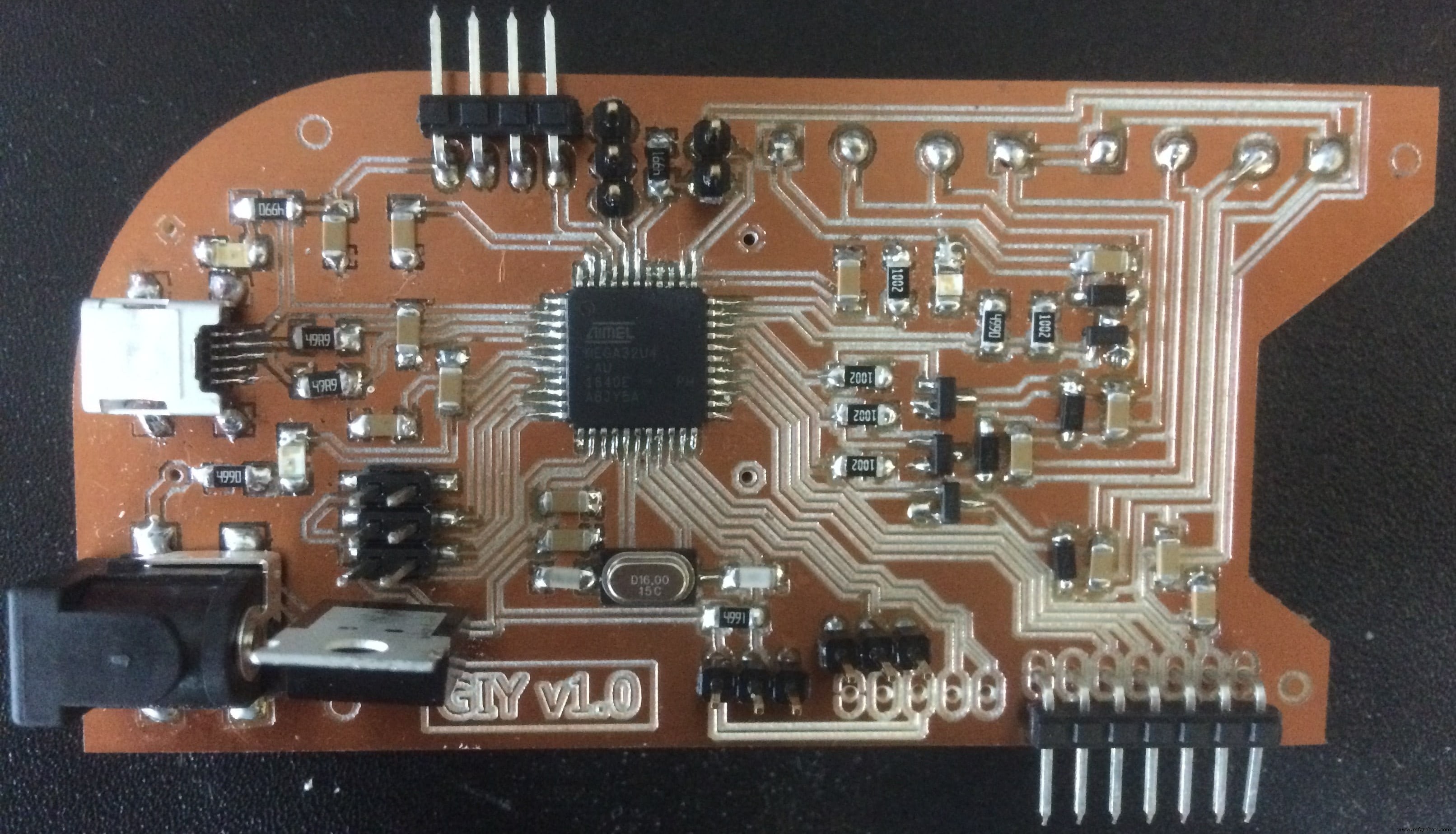
When I plugged in the PCB board to check if everything is fine, I noticed an error. From experience, I know that the error was from a short circuit, because the computer was disconecting the Arduino all the time I connect the VCC and GND to it. So my guess was that somewhere on the board VCC and GND are connected, and using the multimeter, I confirmed that I was right.
It was late, and I got so f*ckin' mad because of that, took me one hour under the microscope to find that little mistake. Here it is:
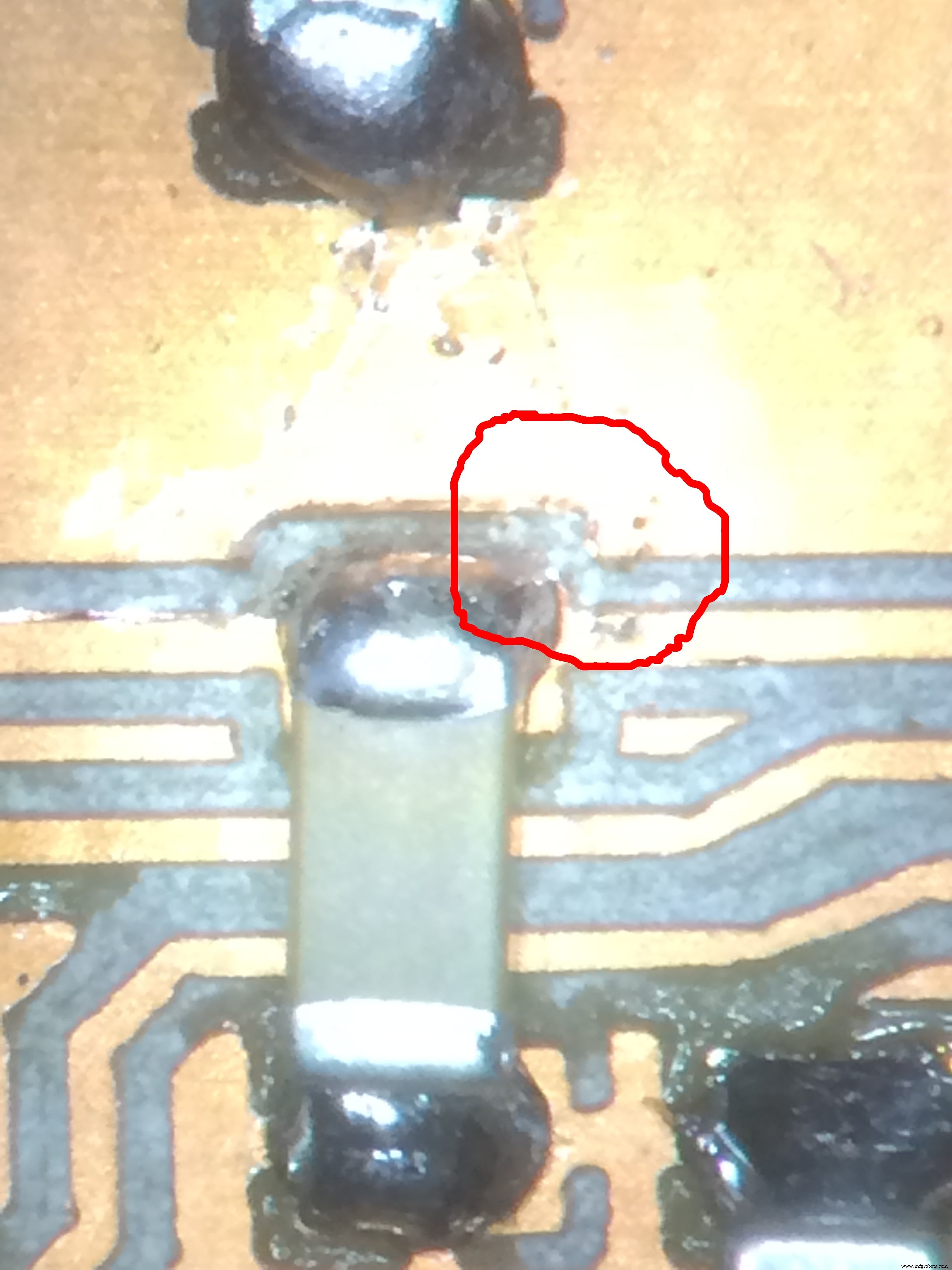
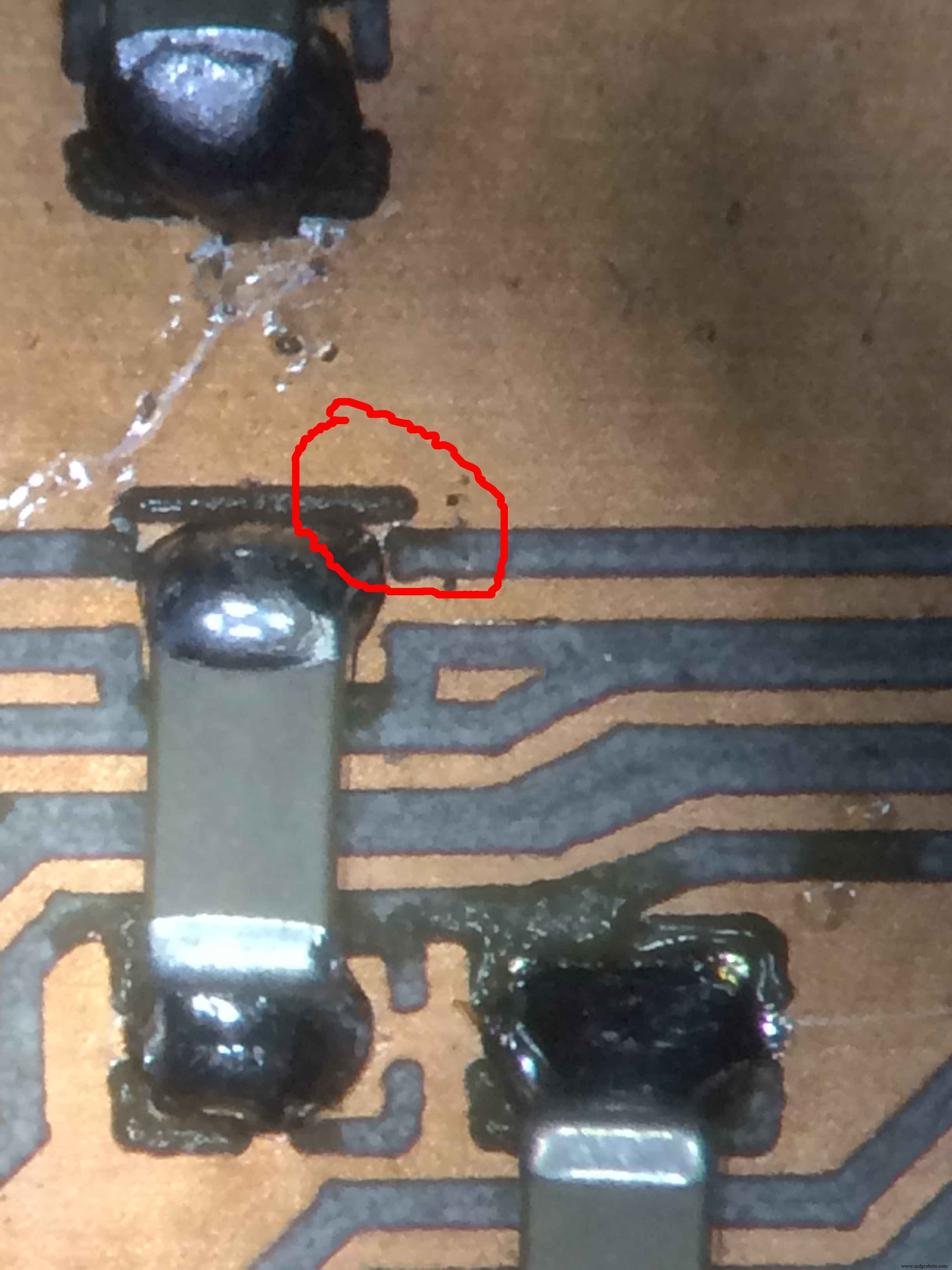
I fixed it by scratching with a knife, and increasing the isolation!
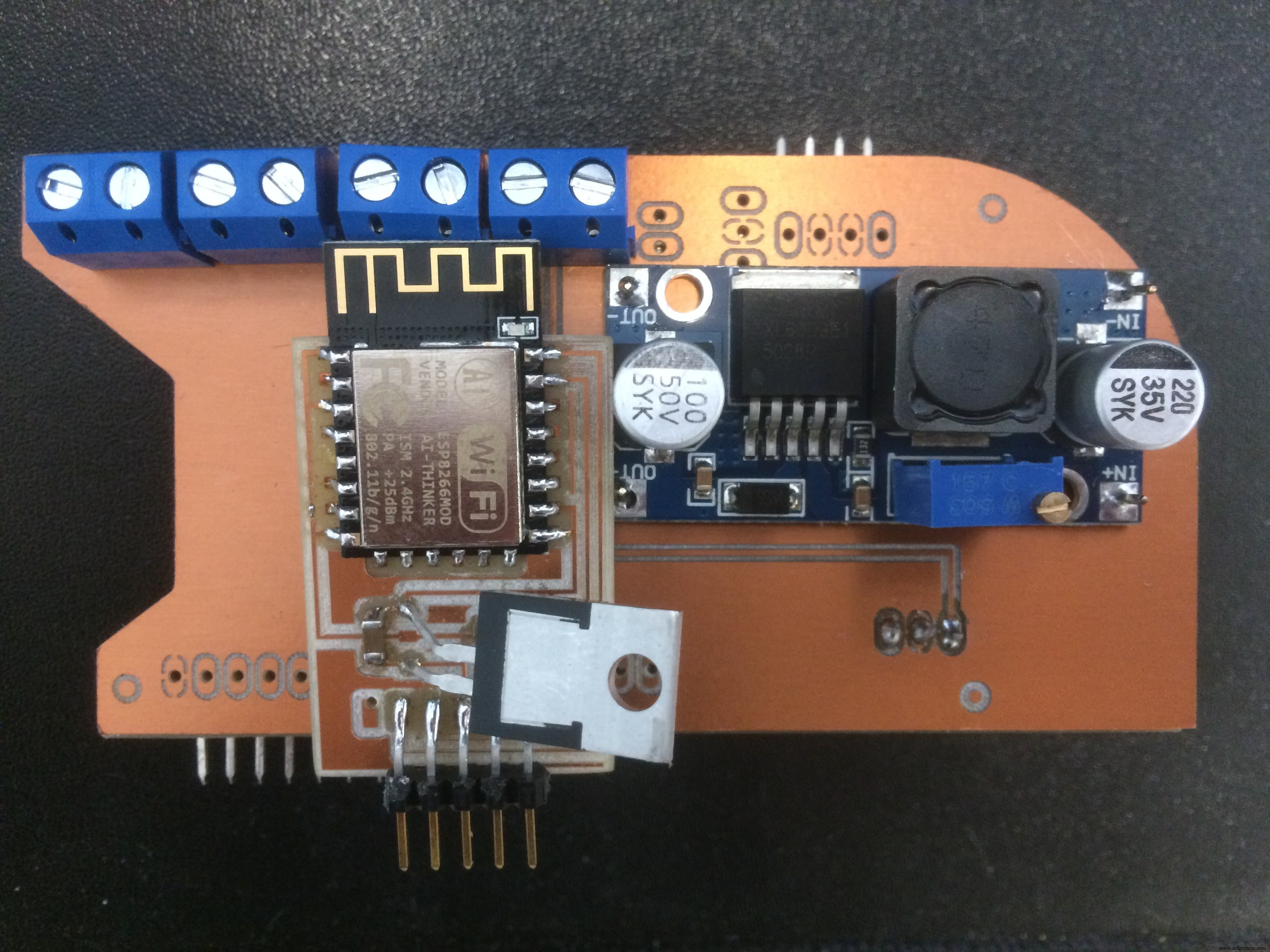
Another thing is placing the Step Up Voltage Reguator on the back side of my board.
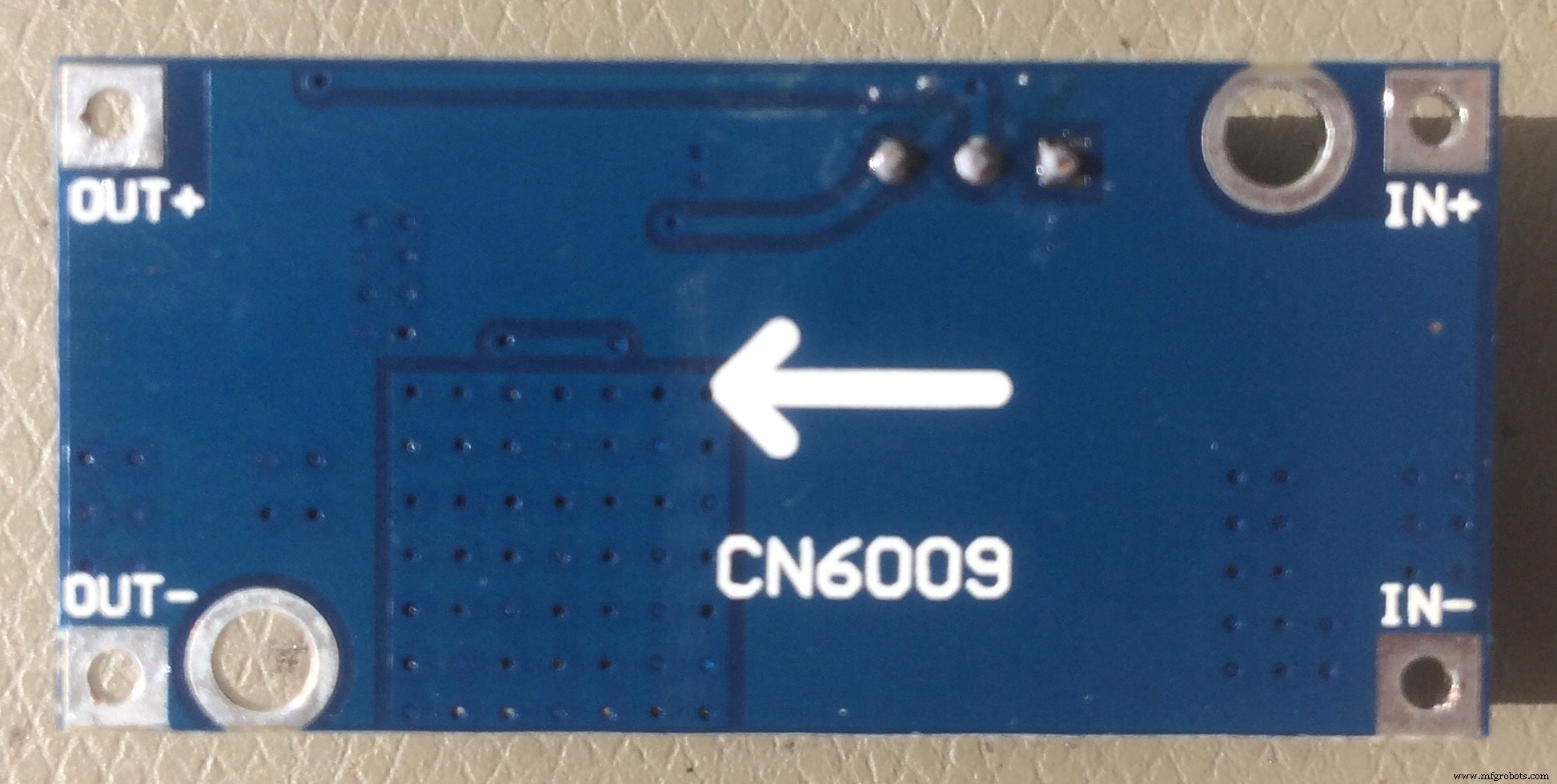
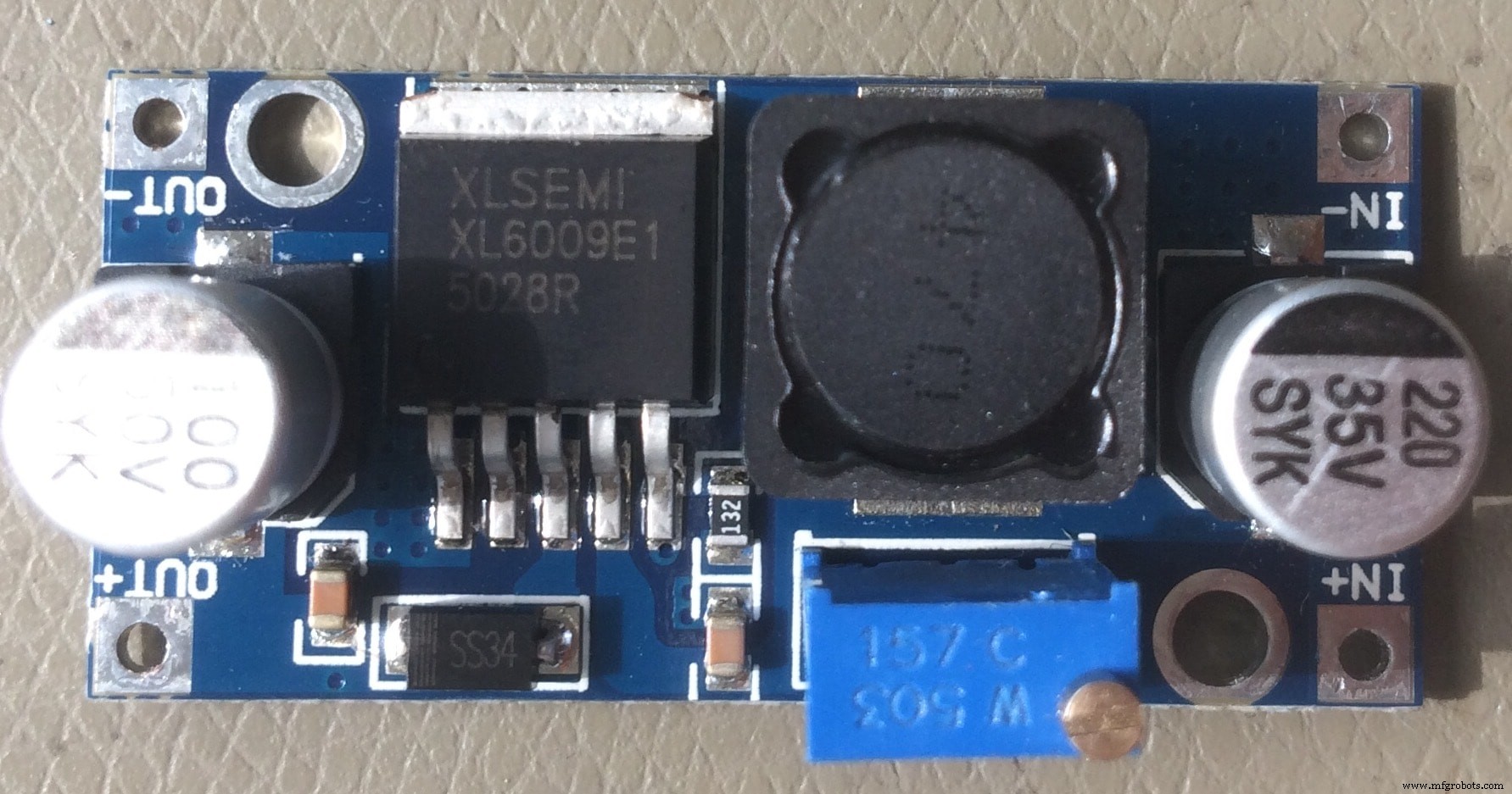
I measured the dimensions in advance, and designed predrilled holes to fix it with the pinheaders. But before soldering it on the back side, I have to calibrate it.
The idea is that when I power the board with 12V, the step up will output 24V necessary for the Ultrasonic Atomizer, which is connected to the MOSFET circuit
I used the bench power supply, with a fixed 12V, to measure the output voltage using a multimeter.
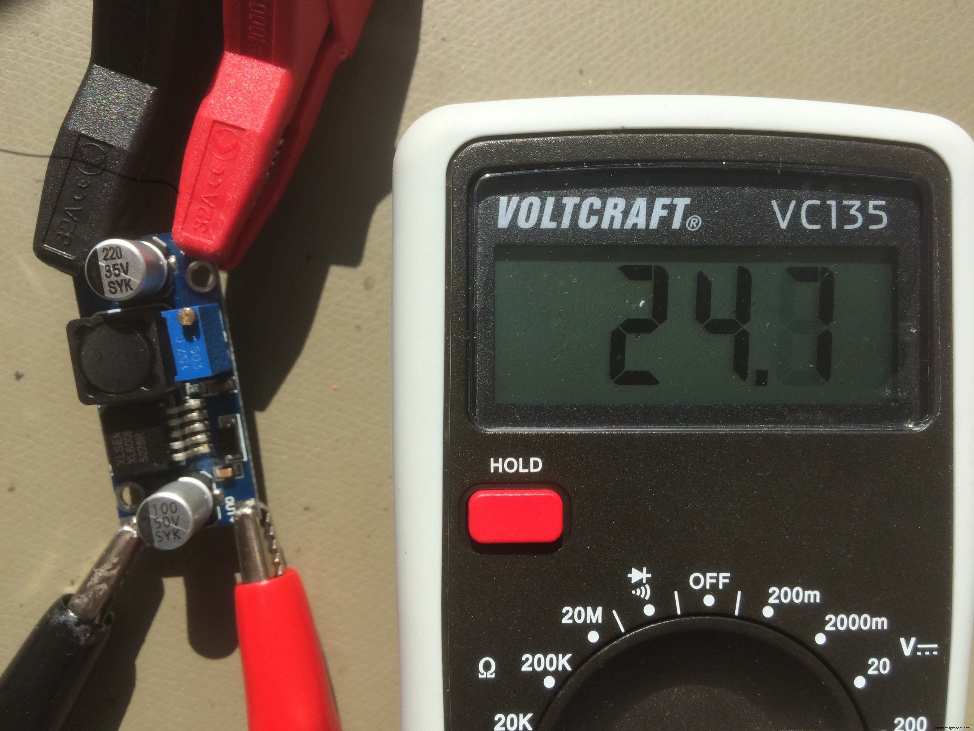
After I adjust the output to the one that I need, 24V in my case, I can solder it to the back side of my board!
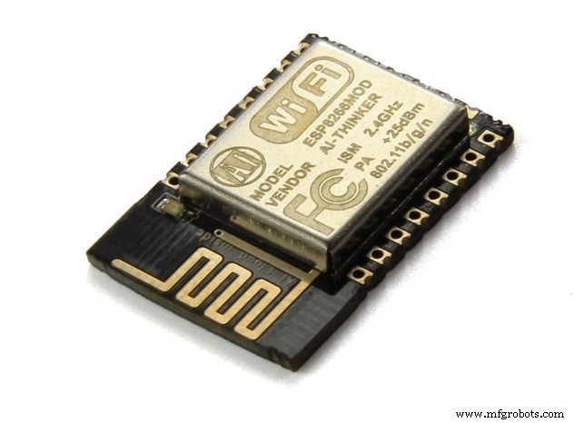
Also on the back side, I placed the WiFi board which I made during the Networking and Communications week!
So, here is The BEAST :
A HERO picture for those who may think that it was easy, and everything went smooth :D
Download Files:
GIY Schematics (.sch)
GIY Layout (.brd)
Board#1 Internal Cut(.png)
Board#1 External Cut (.png)
Board#2 Internal Cut (.png)
Board#2 External Cut (.png)
Wiring &Embedded programming (I/O Devices)
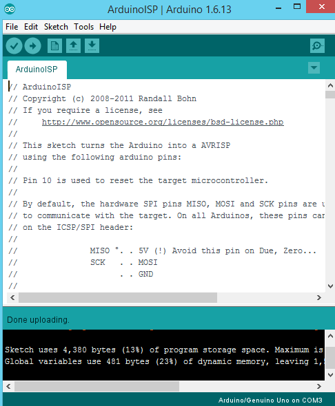
To program my board I used Arduino IDE . I connect the arduino board to the USB hub, in the tools menu select the right board (Arduino Leonardo) and the port, after go to File --> examples and open the Arduino as ISP bosquejo. Upload the code.
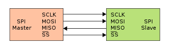
After I see done uploading, which means that the code is uploaded to the board, I disconnect the arduino from the PC. The next step is to connect my PCB board to Arduino using some wires. The connection scheme is this one:
- SCLK:Serial Clock (output from master) ----------> Arduino Pin 13
- MOSI:Master Output Slave Input ----------> Arduino Pin 11
- MISO:Master Input Slave Output ----------> Arduino Pin 12
- VCC:Positive supply voltage ----------> Arduino VCC
- GND:Ground ----------> Arduino GND
- RST:----------> Arduino Pin 10
I connect the arduino board to the USB hub. Under Tools select the right board, select Arduino as ISP programmer, double check the parameters, and press the Burn Bootloader button.
And I see Done Uploading! Good sign)
To test the board, I upload the basic Blink example code:
Ohh, I LOVE that BLINK :D Now let's go to sensors!
First sensor that I want to use is DHT11 - Temperature &Humidity Sensor
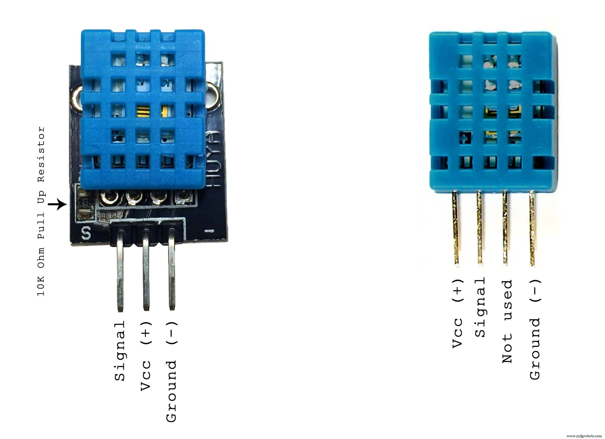
These sensors are very basic and slow, but are great for hobbyists who want to do some basic data logging. The DHT sensors are made of two parts, a capacitive humidity sensor and a thermistor. There is also a very basic chip inside that does some analog to digital conversion and spits out a digital signal with the temperature and humidity. The digital signal is fairly easy to read using any microcontroller.
Some characteristics:
- Ultra low cost
- 3 to 5V power and I/O
- 2.5mA max current use during conversion (while requesting data)
- Good for 20-80% humidity readings with 5% accuracy
- Good for 0-50°C temperature readings ±2°C accuracy
- No more than 1 Hz sampling rate (once every second)
- Body size 15.5mm x 12mm x 5.5mm
- 4 pins with 0.1" spacing
The wiring is pretty easy, just VCC, GND, and any Digital Pin! In my case, I designed in advance the connection for this sensor.
To test it, I will upload a simple sketch. The sketch includes the library DHT.h
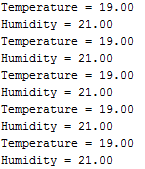
So here is the code:
// DHT11 Temperature and Humidity Sensors Example#include "DHT.h" //include DHT library#define DHTPIN 2 //define as DHTPIN the Pin 2 used to connect the Sensor#define DHTTYPE DHT11 //define the sensor used(DHT11)DHT dht(DHTPIN, DHTTYPE); //create an instance of DHTvoid setup() { Serial.begin(9600); //initialize the Serial communication dht.begin(); //initialize the Serial communication}void loop() { float h =dht.readHumidity(); // reading Humidity float t =dht.readTemperature(); // read Temperature as Celsius (the default) Serial.print("Temperature ="); Serial.println(t, 2); //print the temperature Serial.print("Humidity =");; Serial.println(h, 2); //print the humidity delay(2000); //wait 2 seconds } When I open the Serial Monitor, this is what I get:
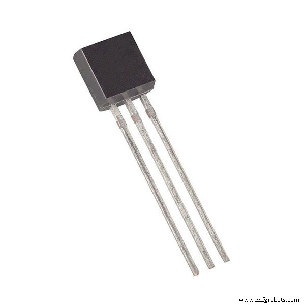
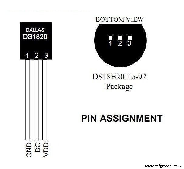
Another sensor which I want to use is DS18B20 - One Wire Digital Temperature Sensor
DS18B20 is 1-Wire digital temperature sensor from Maxim IC. Reports degrees in Celsius with 9 to 12-bit precision, from -55 to 125 (+/-0.5). Each sensor has a unique 64-Bit Serial number etched into it - allows for a huge number of sensors to be used on one data bus.
This is by far one of the most simple digital sensors to hookup. Aside from power and ground, it has a single digital signal pin that I will be connecting to digital pin which I designed in advance. It also requires a 4.7k pull-up resistor between the signal and power pin, which unfortunately I forgot to place on my PCB. That is why, I will solder it manually directly to the sensor cables.
Before I start, I have to download the libraries:OneWire.h and DallasTemperature.h
Upload the following sketch:
// First we include the libraries#include #include #define ONE_WIRE_BUS 3 // Setup a oneWire instance to communicate with any OneWire devices, (not just Maxim/Dallas temperature ICs) OneWire oneWire(ONE_WIRE_BUS); // Pass our oneWire reference to Dallas Temperature. DallasTemperature sensors(&oneWire);void setup(void) { // start serial port Serial.begin(9600); sensors.begin(); } void loop(void) { // call sensors.requestTemperatures() to issue a global temperature (request to all devices on the bus)sensors.requestTemperatures(); // Send the command to get temperature readings Serial.print("Temperature is:"); Serial.print(sensors.getTempCByIndex(0)); //You can have more than one DS18B20 on the same bus. 0 refers to the first IC on the wire delay(1000); } The funny thing is that after I successfully programmed the sensor, It stopped working while I was integrating all the sensors together! I spend quite a long time trying to figure out why it does not work, but due to the limited time, I decided to use another DS18B20 sensor which was available in our FabLab stock, and waterproof it by myself!
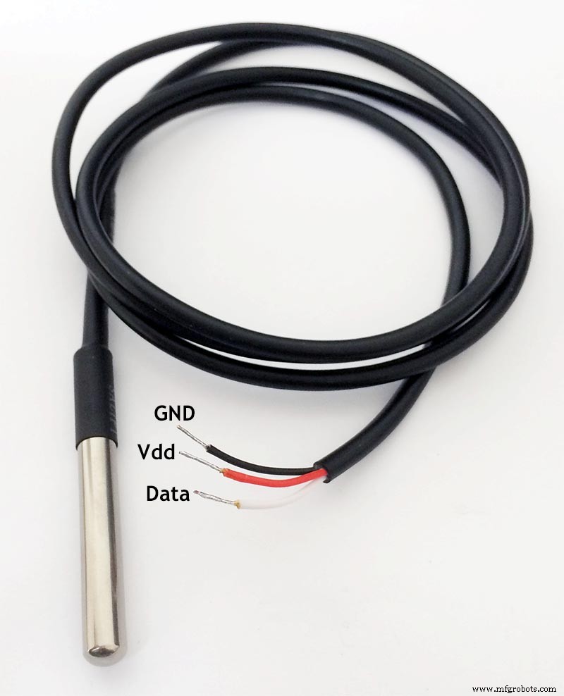
So I took the sensor, and used the datasheet to properly solder the cables, and isolate them from each other using shrink tubes
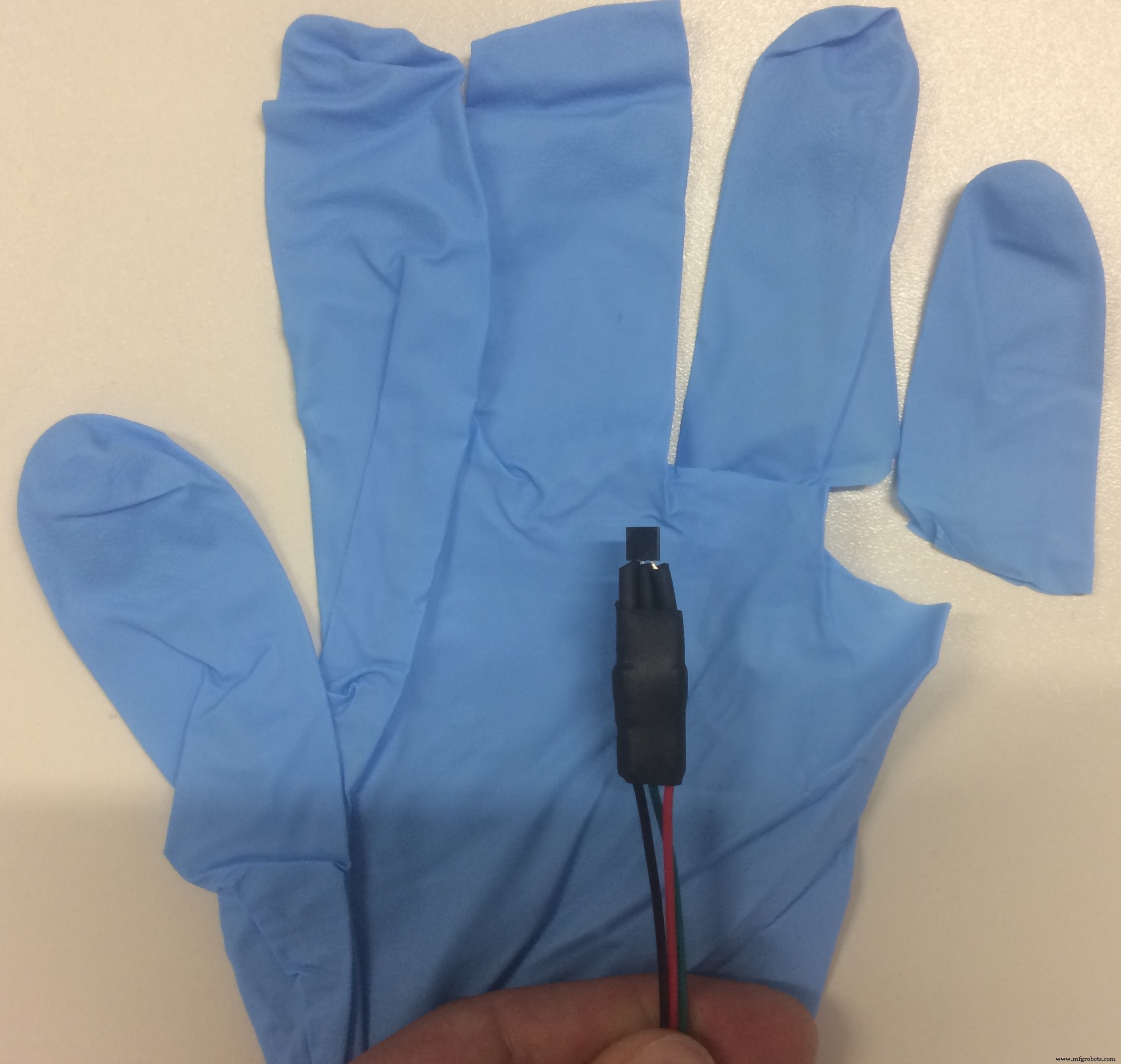
I guess you have got the idea how I am going to waterproof it, right? :D Mama ama engineer!
Said &DONE!
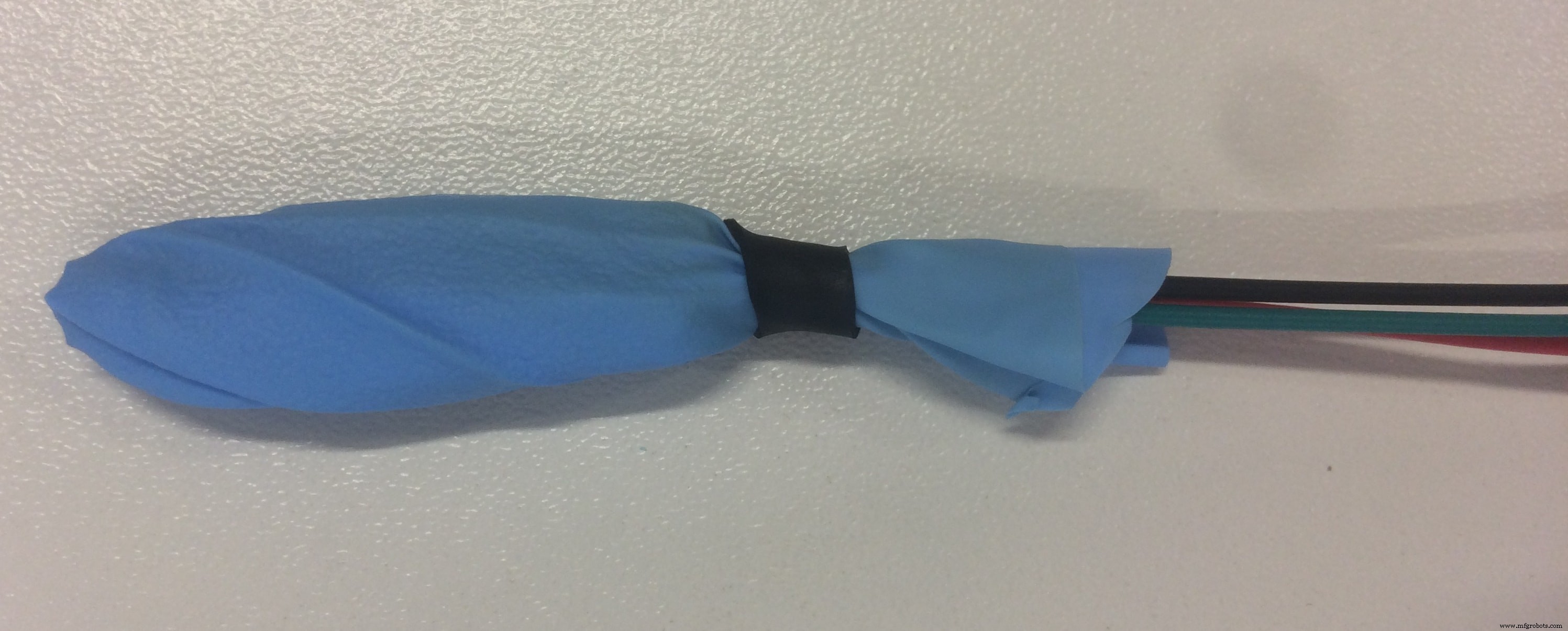
Yeah, I know what it looks like :D but I assure you, its just a hand waterproof sensor. The most important is that it works, and does not leak when submerged in water!
And we go to the next sensor which is LDR =Light Dependent Resistor
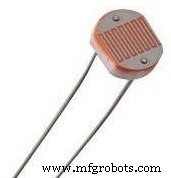
LDR is a passive electronic component, basically a resistor which has a resistance that varies depending of the light intensity. The resistance is very high in darkness, almost high as 1MΩ but when there is light that falls on the LDR, the resistance is falling down to a few KΩ (10-20kΩ @ 10 lux, 2-4kOmega; @ 100 lux) depending on the model.
The LDR gives out an analog voltage when connected to Vcc (5V), which varies in magnitude in direct proportion to the input light intensity on it. That is, the greater the intensity of light, the greater the corresponding voltage from the LDR will be. Since the LDR gives out an analog voltage, it is connected to the analog input pin on the Arduino. The Arduino, with its built-in ADC (Analog to Digital Converter), then converts the analog voltage (from 0-5V) into a digital value in the range of (0-1023). When there is sufficient light in its environment or on its surface, the converted digital values read from the LDR through the Arduino will be in the range of 800-1023.
Here is the sketch code to test the sensor:
int sensorPin =A0; /* select the input pin for LDR */int sensorValue =0; /* variable to store the value coming from the sensor */void setup(void) { Serial.begin(9600); /* start serial port */} void loop(void) { sensorValue =analogRead(sensorPin); // read the value from the sensor // We'll have a few threshholds, qualitatively determined Serial.print("LDR Value ="); Serial.print(sensorValue); if (sensorValue <100) { Serial.println(" (Dark)"); } else if (sensorValue <200) { Serial.println(" (Dim)"); } else if (sensorValue <500) { Serial.println(" (Light)"); } else if (sensorValue <800) { Serial.println(" (Bright)"); } else { Serial.println(" (Very bright)"); } delay(3000);} Next is Water Level Sensor
I want to have a water level sensor in order to receive an alarm when the water container is empty, and its time to add some water. Because I did not think about it in advance, and we did not have any water level sensor in our stock, I decided that I can make my own water sensor!
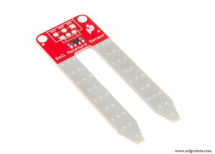
I decided to use the materials available, in my case the Soil Moisture Sensor . The basic principle of the water level sensor is to measure electric conductivity, which is the same for the soil moisture sensor. I thought that If I can calibrate the sensor in a way that will fulfil my requirements, I can use the moisture sensor like an water level sensor) In principle, this is an analog sensor and the data that we will read will be values from 0 to 1024, and the rest is just math!
But as it often happens, the reality is slightly different. When the sensor is not in touch with the water, the analog value is 0, and when I submerge only the tip, the value goes to 800. I used the following sketch to read the values:
/* Print values from analog pin A4 to serial monitor */void setup(){ Serial.begin(9600); }void loop(){ Serial.println(analogRead(A4)); delay(100);} After I can read the values, I calibrated the sensor to give out three different responses:EMPTY! - when the value is 0, LOW when the values are around 800, and Full when the values are more than 900!
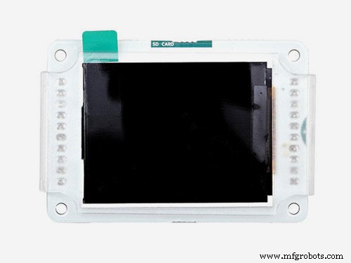
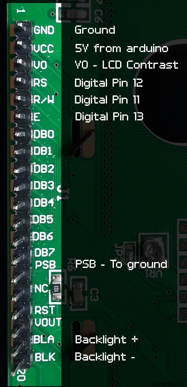
Graphic LCD Display
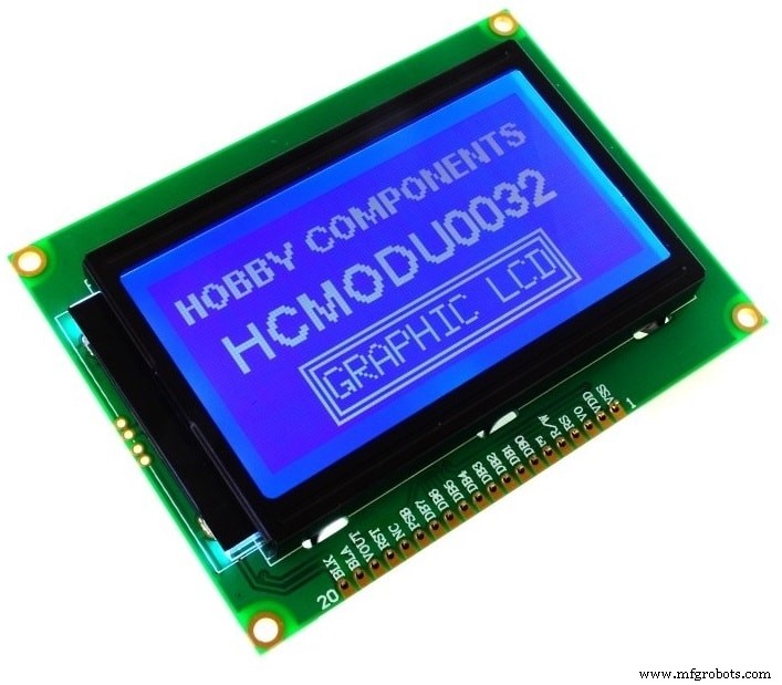
Because usually the LCD displays use a lot of pins, I had to find a way to connect the 128×64 screen in another way, and I DID!!! This way alows using only 3 Digital Pins on the board which is awesome because I may need the rest of the pins for other stuff, and it does not create a mess of wires. I premade the pins for the LCD on my PCB, and this is how I connected everything:
After I connect the LCD, It's time to programm it!
First of all, I have to download the U8glib library from HERE. Another important thing is the declared pins used in the code. The one I used are the following: U8GLIB_ST7920_128X64 u8g(4, 12, 6, U8G_PIN_NONE)
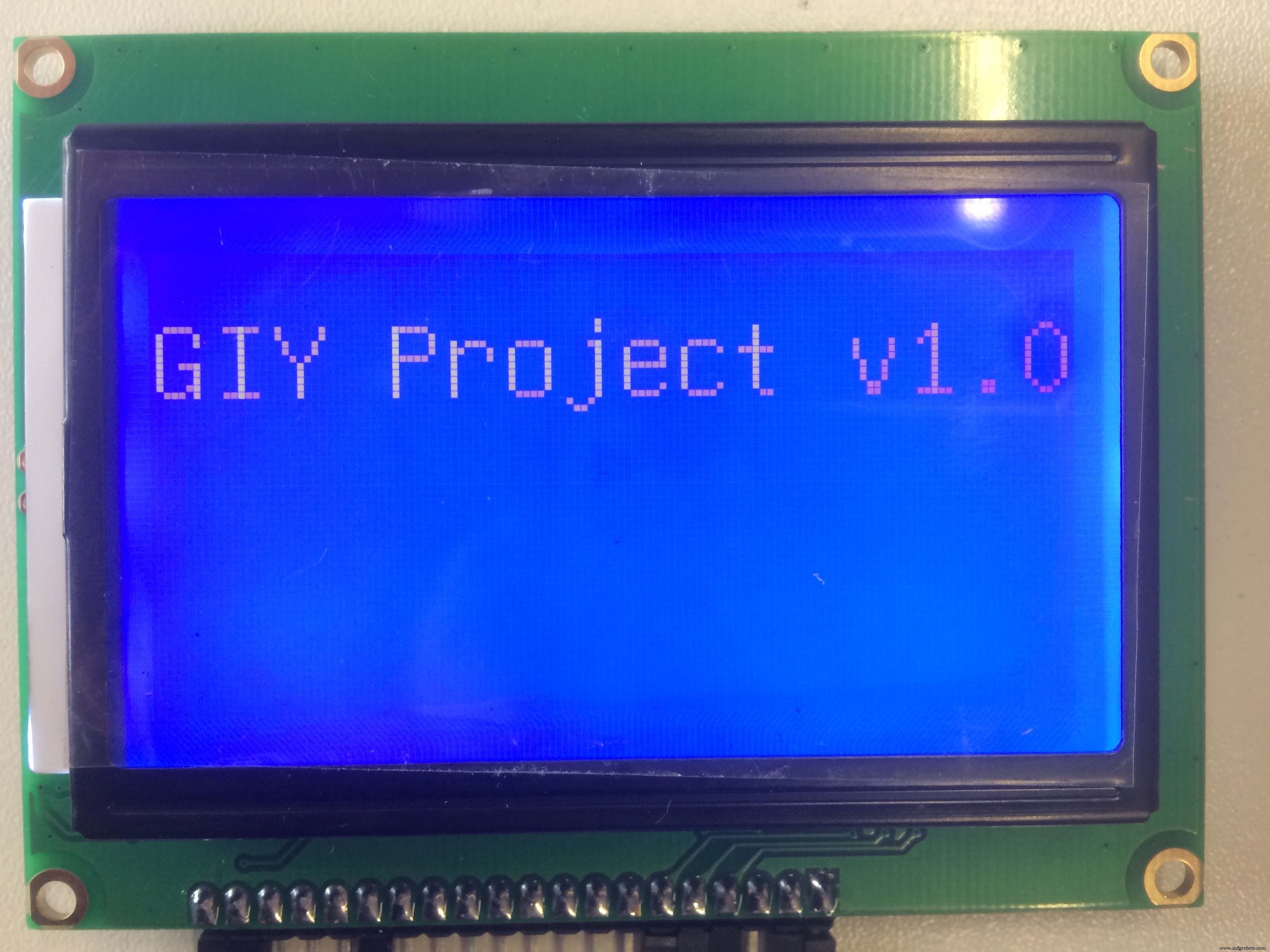
Using the "HELLO WORLD" library example, I came up with this test code:
#include "U8glib.h"U8GLIB_ST7920_128X64 u8g(4, 12, 6, U8G_PIN_NONE);void draw(void) { // graphic commands to redraw the complete screen should be placed here u8g.setFont(u8g_font_unifont); u8g.setPrintPos(0, 20); // call procedure from base class, http://arduino.cc/en/Serial/Print u8g.print("GIY Project v1.0!");}void setup(void) { // flip screen, if required // u8g.setRot180();}void loop(void) { // picture loop u8g.firstPage(); do { draw(); } while( u8g.nextPage() ); // rebuild the picture after some delay delay(500);} And this is what I get:
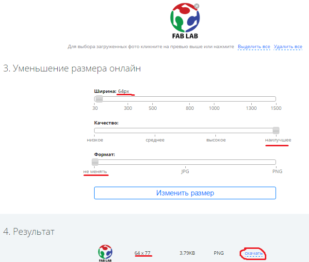
One cool idea that came to my mind was to display the FabLab logo for some seconds, all the time when the display is powered. I spent quite a lot of time on doing this, but I finally did it! In order to display it on the Graphic LCD, I had to have a (.bmp) format picture, and display it as a bitmap.
First thing which I did was download the FabLab logo from the internet as a (.png) file, and reduce it significantly in size, so it fits my small LCD borders. I used the following online service to do that:LINK
These are the configurations I used:
The next step is to convert my small picture into (.bmp) format. I used the following online service to do that:LINK
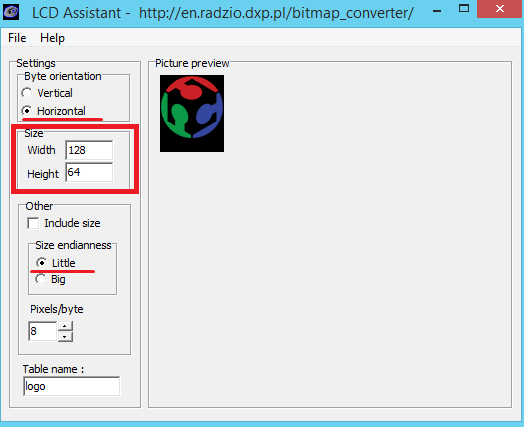
Now, after I have my (.bmp) file, in order to place it into my code, I have to convert it into HEX formación. I used a nice tool called LCD Assistant . To load up an image in LCD Assistant, go to File> Load Image. A preview of the image should open up, make sure it’s the right size – 128 pixels wide, 64 pixels tall . Also make sure the Byte orientation is set to Horizontal and the Size endianness is set to Little . These are the configurations for my LCD Display:
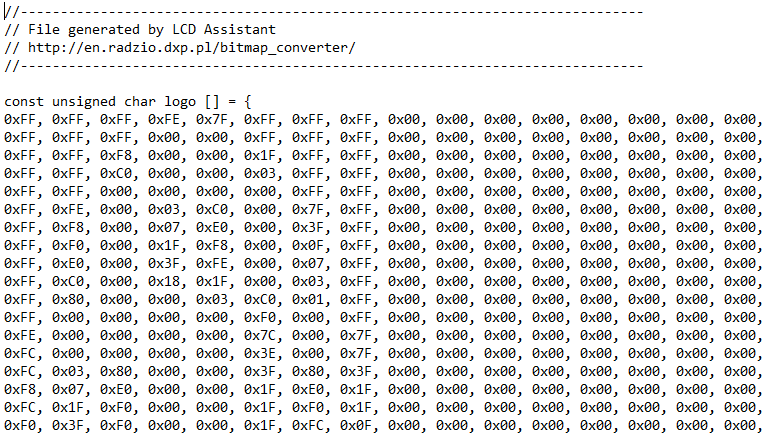
Then I go to File> Save output to generate a temporary text Archivo. Open that text file to have a look at my shiny new array.
pH Sensor
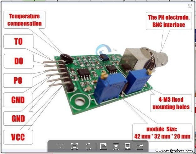
I should admit that this is the most tricky sensor from all that I played with! It is really hard to find any info about the sensor which I am using (logo ph sensor v1.1) , so I decided to make a detailed description about it!
The probe is like a (tiny) battery when placed in a liquid. Depending the pH it output a positive or negative voltage of a couple of millivolts. This value is too small and other tech stuff like impedance make it unusable directly with an Arduino, that's why you need an "op amp". The op amp board just convert the millivolts of the probe into to something acceptable for Arduino (positive between 0 and 5v).
There are 3 common buffer solutions used for pH measurement:pH 4.01, pH 6.86 and pH 9.18 (7.0 and 10.0 exists). I suggest the powder instead the liquid because it's cheaper, expire after longer and the powder can't be contaminated (vs bottle). You should read the product instructions but usually you have to put the content of the bag into 250ml of water and stir. You can use any water with an average pH (6-8) because the powder will saturate the water at the correct pH level. I personally use tap water (pH 7.4) and didn't see any difference between distilled, and demineralized water. Buffers are not stable in the time, this means that you cannot keep the solution for weeks or months.
Now let's talk more about the sensor that I am using!
- Pin To:Should be the temperature but I can't make it work
- Pin Po:Analog input signal
- Pin To:Should be the temperature but I can't make it work
- Pin Do:High/Low 3.3v adjustable limit.
- Pin G/GND:Probe ground. It is useful when the ground is not the same as your Arduino. In some circumstances the ground voltage of the liquid to measure can be different.
- Pin G/GND:Power ground (direct from the board).
- Pin V+/VCC:Input power 5V DC (direct from the board).
- Blue potentiometer (close to BNC):pH offset.
- Blue potentiometer (close to pins):limit adjustment.
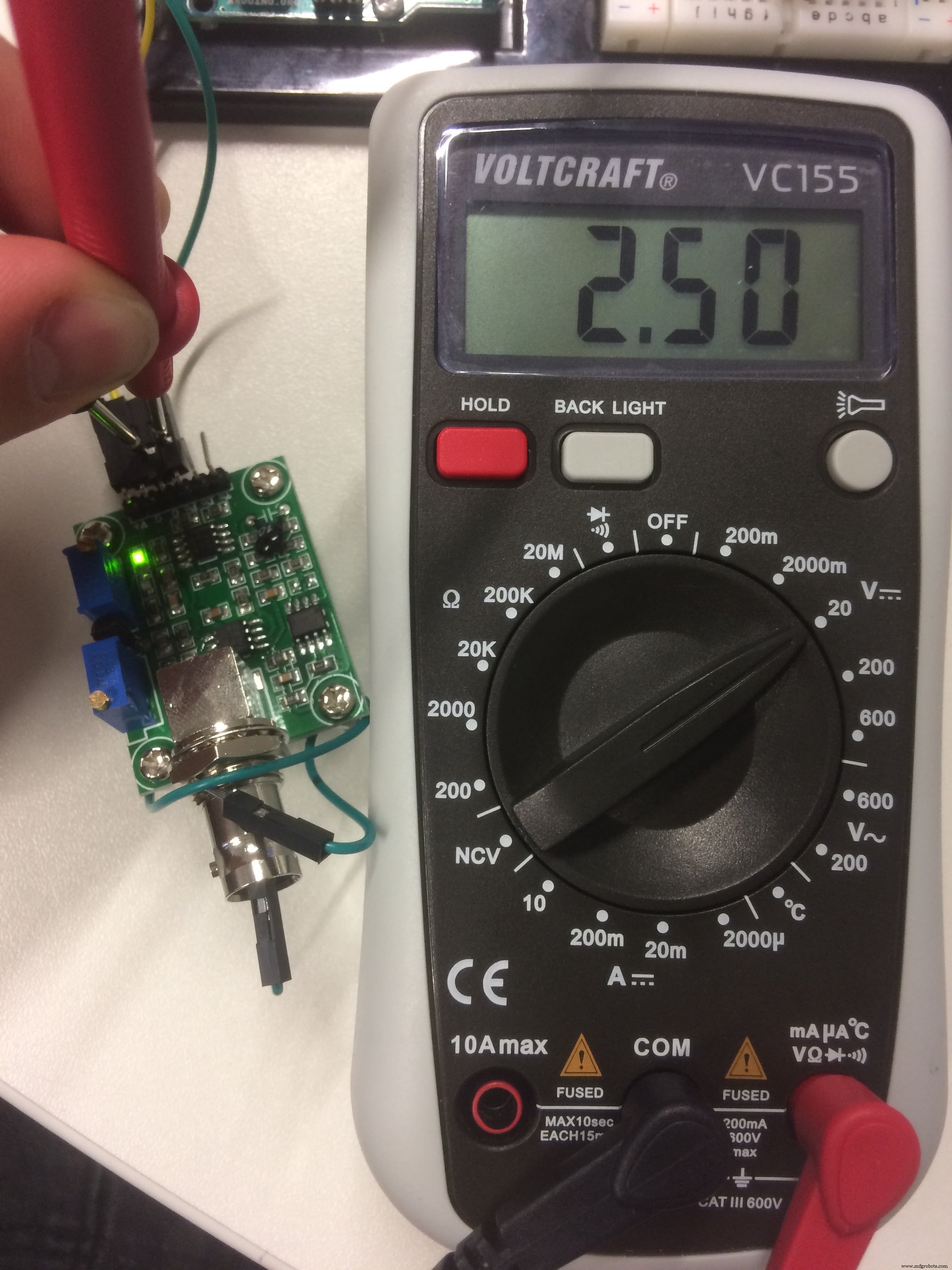
Now let's try to calibrate the sensor! There are 2 different parameters, the "offset" value and the "step" value
The offset is the shifting of all pH values to a specific voltage range. If a pH 7 output a voltage of 2.2v and pH 8 a voltage of 2.1v, then a shift of +0.3v move the pH 7 to 2.5v and the pH 8 to 2.4v. This can be done on the board or via software but it's probably easier on the board because it's probe independent and there are less programming to do.
Connect GND (both) and Vcc to Arduino GND and 5v. Remove the probe and do a short circuit between the the small BNC hole and the external part of BNC. Put a voltmeter (or Arduino) to measure the voltage between GND and Po. Adjust the pot (close BNC) until the output is 2.5v. Now the pH 7 have an exact value of 2.5v (511 with analogRead function) because the probe will output 0 millivolt.
To calibrate the steps I need one or more buffer solutions depending on the range and precision required. Ideally it is better to know the range of the measure with the system. I use water between pH 5 and pH 7, then I choose the buffer 4.01 (and 6.86 to verify my stuff). If you usually measure pH between 8 and 10 choose buffer 9.18 (eventually 6.86 also).
I connect the (clean) probe and put it in the buffer, then let it stabilize for a minute. I know it's stable when it goes up and down (3.04 then 3.05 then 3.03 then 3.04).Take note of the voltmeter (or Arduino) value, in my example it's 3.05v.
That's all, now I can use it with the code below.
int ph_pin =A7; //This is the pin number connected to Povoid setup() { Serial.begin(9600);}void loop() { int measure =analogRead(ph_pin); Serial.print("Measure:"); Serial.print(measure); double voltage =5 / 1024.0 * measure; //classic digital to voltage conversion Serial.print("\tVoltage:"); Serial.print(voltage, 3); // PH_step =(voltage@PH7 - voltage@PH4) / (PH7 - PH4) // PH_probe =PH7 - ((voltage@PH7 - voltage@probe) / PH_step) float Po =7 + ((2.5 - voltage) / 0.18); Serial.print("\tPH:"); Serial.print(Po, 3); Serial.println (""); delay(2000);} The PH_step calculation is quite simple. I take the difference between the two known voltage, in my example 2.5v@pH7 and 3.05v@pH4.01 which is -0.55v. It's the voltage range equivalent of the pH range from 7 to 4.01, which is 2.99 pH units. A small division of the voltage by pH units gives a volts per pH number (0, 1839... in my case).
The PH_probe is calculated by taking the known pH 7 voltage (2.5v) where we add some PH_step to match the probe voltage. This means that a pH of 8 has a voltage value of 2.5v (pH 7) + 0.1839 (1 unit/step); pH 9 then is 2.5v + 0.1839 + 0.1839 =2.87v.
No magic, JUST MATH :D
MOSFET output:
I connected the RGB LED stripe and the Ultrasonic Atomizer to the MOSFET circuit outputs, which are controlled by digital pins. For the LED lights, I stated in the setup digitalWrite (LED, HIGH); , which means that the LED will switch on all the time when the system is powered. For the Fog maker, I made an If function depending on the water level value. If there is water, the fog maker is ON, if there is no water, EMPTY!, then the fog is OFF!
Now Let's put things together!
Here I came up with my final code:
#include "dht.h"#include "U8glib.h"#include #include #define DHT11_PIN 2 // what digital pin we're connected to#define ONE_WIRE_BUS 3#define WATER_LEVEL A4#define LDR_PIN A3#define PH_PIN A5#define GROW_LIGHT 10#define FOG_PUMP 13int waterLevel;int LightLevel;int pH;dht DHT;OneWire oneWire(ONE_WIRE_BUS); DallasTemperature waterTemp(&oneWire);U8GLIB_ST7920_128X64 u8g(4, 12, 6, U8G_PIN_NONE);const unsigned char logo [] PROGMEM ={0xFF, 0xFF, 0xFF, 0xFE, 0x7F, 0xFF, 0xFF, 0xFF, 0x00, 0x00, 0x00, 0x00, 0x00, 0x00, 0x00, 0x00,0xFF, 0xFF, 0xFF, 0x00, 0x00, 0xFF, 0xFF, 0xFF, 0x00, 0x00, 0x00, 0x00, 0x00, 0x00, 0x00, 0x00,0xFF, 0xFF, 0xF8, 0x00, 0x00, 0x1F, 0xFF, 0xFF, 0x00, 0x00, 0x00, 0x00, 0x00, 0x00, 0x00, 0x00,0xFF, 0xFF, 0xC0, 0x00, 0x00, 0x03, 0xFF, 0xFF, 0x00, 0x00, 0x00, 0x00, 0x00, 0x00, 0x00, 0x00,0xFF, 0xFF, 0x00, 0x00, 0x00, 0x00, 0xFF, 0xFF, 0x00, 0x00, 0x00, 0x00, 0x00, 0x00, 0x00, 0x00,0xFF, 0xFE, 0x00, 0x03, 0xC0, 0x00, 0x7F, 0xFF, 0x00, 0x00, 0x00, 0x00, 0x00, 0x00, 0x00, 0x00,0xFF, 0xF8, 0x00, 0x07, 0xE0, 0x00, 0x3F, 0xFF, 0x00, 0x00, 0x00, 0x00, 0x00, 0x00, 0x00, 0x00,0xFF, 0xF0, 0x00, 0x1F, 0xF8, 0x00, 0x0F, 0xFF, 0x00, 0x00, 0x00, 0x00, 0x00, 0x00, 0x00, 0x00,0xFF, 0xE0, 0x00, 0x3F, 0xFE, 0x00, 0x07, 0xFF, 0x00, 0x00, 0x00, 0x00, 0x00, 0x00, 0x00, 0x00,0xFF, 0xC0, 0x00, 0x18, 0x1F, 0x00, 0x03, 0xFF, 0x00, 0x00, 0x00, 0x00, 0x00, 0x00, 0x00, 0x00,0xFF, 0x80, 0x00, 0x00, 0x03, 0xC0, 0x01, 0xFF, 0x00, 0x00, 0x00, 0x00, 0x00, 0x00, 0x00, 0x00,0xFF, 0x00, 0x00, 0x00, 0x00, 0xF0, 0x00, 0xFF, 0x00, 0x00, 0x00, 0x00, 0x00, 0x00, 0x00, 0x00,0xFE, 0x00, 0x00, 0x00, 0x00, 0x7C, 0x00, 0x7F, 0x00, 0x00, 0x00, 0x00, 0x00, 0x00, 0x00, 0x00,0xFC, 0x00, 0x00, 0x00, 0x00, 0x3E, 0x00, 0x7F, 0x00, 0x00, 0x00, 0x00, 0x00, 0x00, 0x00, 0x00,0xFC, 0x03, 0x80, 0x00, 0x00, 0x3F, 0x80, 0x3F, 0x00, 0x00, 0x00, 0x00, 0x00, 0x00, 0x00, 0x00,0xF8, 0x07, 0xE0, 0x00, 0x00, 0x1F, 0xE0, 0x1F, 0x00, 0x00, 0x00, 0x00, 0x00, 0x00, 0x00, 0x00,0xFC, 0x1F, 0xF0, 0x00, 0x00, 0x1F, 0xF0, 0x1F, 0x00, 0x00, 0x00, 0x00, 0x00, 0x00, 0x00, 0x00,0xF0, 0x3F, 0xF0, 0x00, 0x00, 0x1F, 0xFC, 0x0F, 0x00, 0x00, 0x00, 0x00, 0x00, 0x00, 0x00, 0x00,0xF0, 0xFF, 0xF0, 0x00, 0x00, 0x1F, 0xFF, 0x0F, 0x00, 0x00, 0x00, 0x00, 0x00, 0x00, 0x00, 0x00,0xE0, 0xFF, 0xF0, 0x00, 0x00, 0x3F, 0xFF, 0x07, 0x00, 0x00, 0x00, 0x00, 0x00, 0x00, 0x00, 0x00,0xE0, 0xFF, 0xF0, 0x00, 0x00, 0x3F, 0xFF, 0x07, 0x00, 0x00, 0x00, 0x00, 0x00, 0x00, 0x00, 0x00,0xC0, 0xFF, 0xF8, 0x00, 0x00, 0x7F, 0xFF, 0x03, 0x00, 0x00, 0x00, 0x00, 0x00, 0x00, 0x00, 0x00,0xC0, 0xFF, 0xFC, 0x00, 0x00, 0xFF, 0xFF, 0x03, 0x00, 0x00, 0x00, 0x00, 0x00, 0x00, 0x00, 0x00,0xC0, 0xFF, 0xFF, 0x00, 0x01, 0xFF, 0xFF, 0x03, 0x00, 0x00, 0x00, 0x00, 0x00, 0x00, 0x00, 0x00,0x80, 0xFF, 0xFF, 0xC0, 0x07, 0xFF, 0xFF, 0x01, 0x00, 0x00, 0x00, 0x00, 0x00, 0x00, 0x00, 0x00,0x80, 0xFF, 0xFF, 0xFF, 0xFF, 0xFF, 0xFF, 0x01, 0x00, 0x00, 0x00, 0x00, 0x00, 0x00, 0x00, 0x00,0x80, 0xFF, 0xFF, 0xFF, 0xFF, 0xFF, 0xFF, 0x01, 0x00, 0x00, 0x00, 0x00, 0x00, 0x00, 0x00, 0x00,0x80, 0xFF, 0xFF, 0xFF, 0xFF, 0xFF, 0xFF, 0x01, 0x00, 0x00, 0x00, 0x00, 0x00, 0x00, 0x00, 0x00,0x80, 0xFE, 0x1F, 0xFF, 0xFF, 0xF0, 0x3C, 0x01, 0x00, 0x00, 0x00, 0x00, 0x00, 0x00, 0x00, 0x00,0x80, 0xF8, 0x03, 0xFF, 0xFF, 0xC0, 0x10, 0x01, 0x00, 0x00, 0x00, 0x00, 0x00, 0x00, 0x00, 0x00,0x80, 0xF0, 0x01, 0xFF, 0xFF, 0x80, 0x00, 0x01, 0x00, 0x00, 0x00, 0x00, 0x00, 0x00, 0x00, 0x00,0x00, 0xF0, 0x00, 0xFF, 0xFF, 0x00, 0x00, 0x01, 0x00, 0x00, 0x00, 0x00, 0x00, 0x00, 0x00, 0x00,0x00, 0xE0, 0x00, 0x7F, 0xFE, 0x00, 0x00, 0x01, 0x00, 0x00, 0x00, 0x00, 0x00, 0x00, 0x00, 0x00,0x80, 0xE0, 0x00, 0x3F, 0xFC, 0x00, 0x00, 0x01, 0x00, 0x00, 0x00, 0x00, 0x00, 0x00, 0x00, 0x00,0x80, 0xE0, 0x00, 0x1F, 0xFC, 0x00, 0x00, 0x01, 0x00, 0x00, 0x00, 0x00, 0x00, 0x00, 0x00, 0x00,0x80, 0xE0, 0x00, 0x1F, 0xF8, 0x00, 0x00, 0x01, 0x00, 0x00, 0x00, 0x00, 0x00, 0x00, 0x00, 0x00,0x80, 0xE0, 0x00, 0x0F, 0xF8, 0x00, 0x00, 0x01, 0x00, 0x00, 0x00, 0x00, 0x00, 0x00, 0x00, 0x00,0x80, 0xE0, 0x00, 0x0F, 0xF0, 0x00, 0x00, 0x01, 0x00, 0x00, 0x00, 0x00, 0x00, 0x00, 0x00, 0x00,0x80, 0xE0, 0x00, 0x0F, 0xF0, 0x00, 0x01, 0x01, 0x00, 0x00, 0x00, 0x00, 0x00, 0x00, 0x00, 0x00,0x80, 0xE0, 0x00, 0x07, 0xF0, 0x00, 0x07, 0x01, 0x00, 0x00, 0x00, 0x00, 0x00, 0x00, 0x00, 0x00,0xC0, 0xF0, 0x00, 0x07, 0xF0, 0x00, 0x07, 0x03, 0x00, 0x00, 0x00, 0x00, 0x00, 0x00, 0x00, 0x00,0xC0, 0xF0, 0x00, 0x07, 0xF0, 0x00, 0x0F, 0x03, 0x00, 0x00, 0x00, 0x00, 0x00, 0x00, 0x00, 0x00,0xC0, 0xF8, 0x00, 0x07, 0xF0, 0x00, 0x0F, 0x03, 0x00, 0x00, 0x00, 0x00, 0x00, 0x00, 0x00, 0x00,0xC0, 0xF8, 0x00, 0x07, 0xF0, 0x00, 0x1F, 0x07, 0x00, 0x00, 0x00, 0x00, 0x00, 0x00, 0x00, 0x00,0xE0, 0xFC, 0x00, 0x07, 0xF0, 0x00, 0x1F, 0x07, 0x00, 0x00, 0x00, 0x00, 0x00, 0x00, 0x00, 0x00,0xE0, 0xFE, 0x00, 0x0F, 0xF0, 0x00, 0x3F, 0x07, 0x00, 0x00, 0x00, 0x00, 0x00, 0x00, 0x00, 0x00,0xF0, 0x3E, 0x00, 0x0F, 0xF0, 0x00, 0x7C, 0x0F, 0x00, 0x00, 0x00, 0x00, 0x00, 0x00, 0x00, 0x00,0xF0, 0x1E, 0x00, 0x1F, 0xF8, 0x00, 0xF8, 0x0F, 0x00, 0x00, 0x00, 0x00, 0x00, 0x00, 0x00, 0x00,0xF8, 0x06, 0x00, 0x1F, 0xFC, 0x01, 0xE0, 0x1F, 0x00, 0x00, 0x00, 0x00, 0x00, 0x00, 0x00, 0x00,0xFC, 0x00, 0x00, 0x7F, 0xFF, 0x0F, 0x80, 0x3F, 0x00, 0x00, 0x00, 0x00, 0x00, 0x00, 0x00, 0x00,0xFC, 0x00, 0x00, 0x7F, 0xFF, 0xFF, 0x00, 0x3F, 0x00, 0x00, 0x00, 0x00, 0x00, 0x00, 0x00, 0x00,0xFE, 0x00, 0x00, 0x7F, 0xFF, 0xFC, 0x00, 0x7F, 0x00, 0x00, 0x00, 0x00, 0x00, 0x00, 0x00, 0x00,0xFF, 0x00, 0x00, 0x7F, 0xFF, 0xF0, 0x00, 0xFF, 0x00, 0x00, 0x00, 0x00, 0x00, 0x00, 0x00, 0x00,0xFF, 0x80, 0x00, 0x7F, 0xFF, 0xC0, 0x01, 0xFF, 0x00, 0x00, 0x00, 0x00, 0x00, 0x00, 0x00, 0x00,0xFF, 0xC0, 0x00, 0x7F, 0xFF, 0x80, 0x03, 0xFF, 0x00, 0x00, 0x00, 0x00, 0x00, 0x00, 0x00, 0x00,0xFF, 0xE0, 0x00, 0x7F, 0xFE, 0x00, 0x07, 0xFF, 0x00, 0x00, 0x00, 0x00, 0x00, 0x00, 0x00, 0x00,0xFF, 0xF0, 0x00, 0x1F, 0xF8, 0x00, 0x0F, 0xFF, 0x00, 0x00, 0x00, 0x00, 0x00, 0x00, 0x00, 0x00,0xFF, 0xF8, 0x00, 0x0F, 0xF0, 0x00, 0x1F, 0xFF, 0x00, 0x00, 0x00, 0x00, 0x00, 0x00, 0x00, 0x00,0xFF, 0xFC, 0x00, 0x03, 0xC0, 0x00, 0x3F, 0xFF, 0x00, 0x00, 0x00, 0x00, 0x00, 0x00, 0x00, 0x00,0xFF, 0xFF, 0x00, 0x00, 0x00, 0x00, 0xFF, 0xFF, 0x00, 0x00, 0x00, 0x00, 0x00, 0x00, 0x00, 0x00,0xFF, 0xFF, 0xC0, 0x00, 0x00, 0x03, 0xFF, 0xFF, 0x00, 0x00, 0x00, 0x00, 0x00, 0x00, 0x00, 0x00,0xFF, 0xFF, 0xF0, 0x00, 0x00, 0x1F, 0xFF, 0xFF, 0x00, 0x00, 0x00, 0x00, 0x00, 0x00, 0x00, 0x00,0xFF, 0xFF, 0xFE, 0x00, 0x00, 0x7F, 0xFF, 0xFF, 0x00, 0x00, 0x00, 0x00, 0x00, 0x00, 0x00, 0x00,0xFF, 0xFF, 0xFF, 0xFD, 0x3F, 0xFF, 0xFF, 0xFF, 0x00, 0x00, 0x00, 0x00, 0x00, 0x00, 0x00, 0x00};bool first;float hum =0.0;double T=0.0;void dht_test(float * humPerc);void setup(void) { waterTemp.begin(); pinMode (GROW_LIGHT, OUTPUT); pinMode (FOG_PUMP, OUTPUT); digitalWrite (GROW_LIGHT, HIGH); first =true; // assign default color value if ( u8g.getMode() ==U8G_MODE_R3G3B2 ) { u8g.setColorIndex(255); // white } else if ( u8g.getMode() ==U8G_MODE_GRAY2BIT ) { u8g.setColorIndex(3); // max intensity } else if ( u8g.getMode() ==U8G_MODE_BW ) { u8g.setColorIndex(1); // pixel on } else if ( u8g.getMode() ==U8G_MODE_HICOLOR ) { u8g.setHiColorByRGB(255,255,255); } // picture loop u8g.firstPage(); do { u8g.drawBitmapP( 32, 0, 16, 64, logo); } while( u8g.nextPage() ); dht_test(&hum);}void RefreshDisplay(float * humPerc, double *T, int *WL, int *LL, int *pH_value) { u8g.setFont(u8g_font_fub11); u8g.setFontRefHeightExtendedText(); u8g.setDefaultForegroundColor(); u8g.setFontPosTop(); u8g.drawStr( 4, 0, "Hum%"); u8g.setPrintPos( 68, 0); u8g.print( *humPerc); u8g.drawStr( 4, 15, "Temp"); u8g.setPrintPos( 68, 15); u8g.print( *T); u8g.drawStr( 4, 30, "Wlvl"); if (*WL ==0){ u8g.drawStr (68, 30,"EMPTY!"); digitalWrite (FOG_PUMP, LOW); } else{ if (*WL <800) u8g.drawStr (68, 30,"LOW"); else { digitalWrite(FOG_PUMP, HIGH); u8g.drawStr (68, 30,"HIGH"); } } if (*LL <100) { u8g.drawStr (68, 45,"Dark"); } else if (*LL <200) { u8g.drawStr (68, 45,"Dim"); } else if (*LL <500) { u8g.drawStr (68, 45, "Light"); } else if (*LL <800) { u8g.drawStr (68, 45,"Bright"); } else { u8g.drawStr (68, 45,"2Bright"); } double voltage =5.0 / 1024.0 * (*pH_value); float Po =7 + ((2.5 - voltage) / 0.18); u8g.drawStr (4, 45,"pH"); u8g.setPrintPos( 28, 45); u8g.print( Po); }void loop(void) {waterTemp.requestTemperatures();T =waterTemp.getTempCByIndex(0);waterLevel =analogRead(WATER_LEVEL);LightLevel =analogRead(LDR_PIN);pH =analogRead (PH_PIN);char status;int chk =DHT.read11(DHT11_PIN);hum =DHT.humidity; dht_test(&hum); if(first) { first =false; } else { u8g.firstPage(); do { RefreshDisplay(&hum, &T,&waterLevel, &LightLevel, &pH); } while( u8g.nextPage() ); }}void dht_test(float * humPerc) { // Wait a few seconds between measurements. delay(1000);}
Download Files:
GIY Final Code (.ino)
3D Design &3D Printing
Actually for my final system, I used a lot of 3D design and 3D printing technique. I used two different printers, and played a lot with the settings until I got the desired result!
For 3D design, I used which as I mentioned before, is my favourite CAD software! I will not go too much into details of how to create simple shapes, and extrude objects, all this could be found during my Computer-Aided Design week, where I learned how to use diferent softwares, as well as 3D Scanning and Printing week.

The main task was to design the physical appearence of my system! The challenge was that I wanted it to look SEXY!!!
The aesthetics was a very important criteria, as well as functionality! The system should also be assemblable, which makes it even more challenging. I also wanted to integrate the skills which I learned like 3D printing, CNC milling, Laser cutting etc.
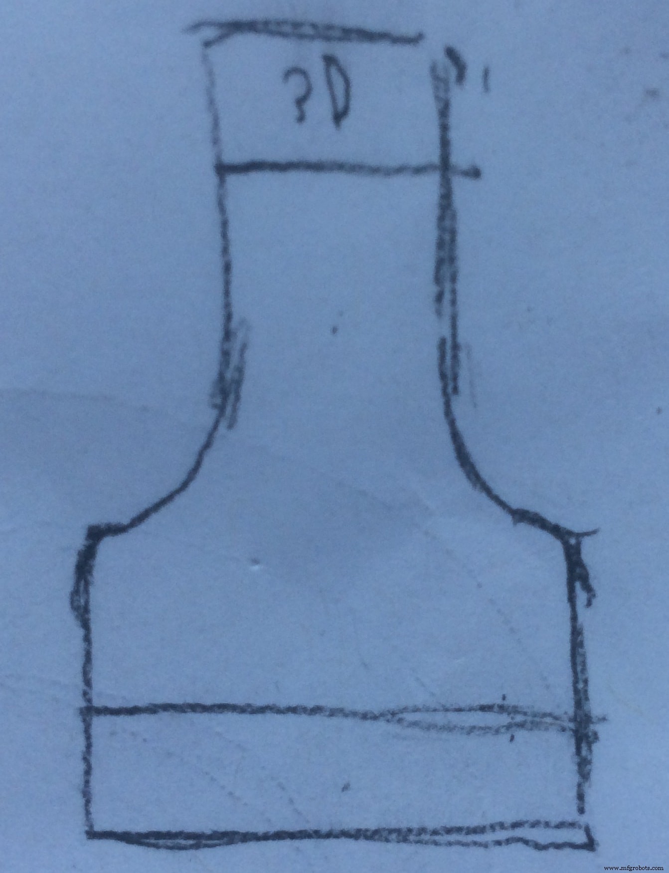
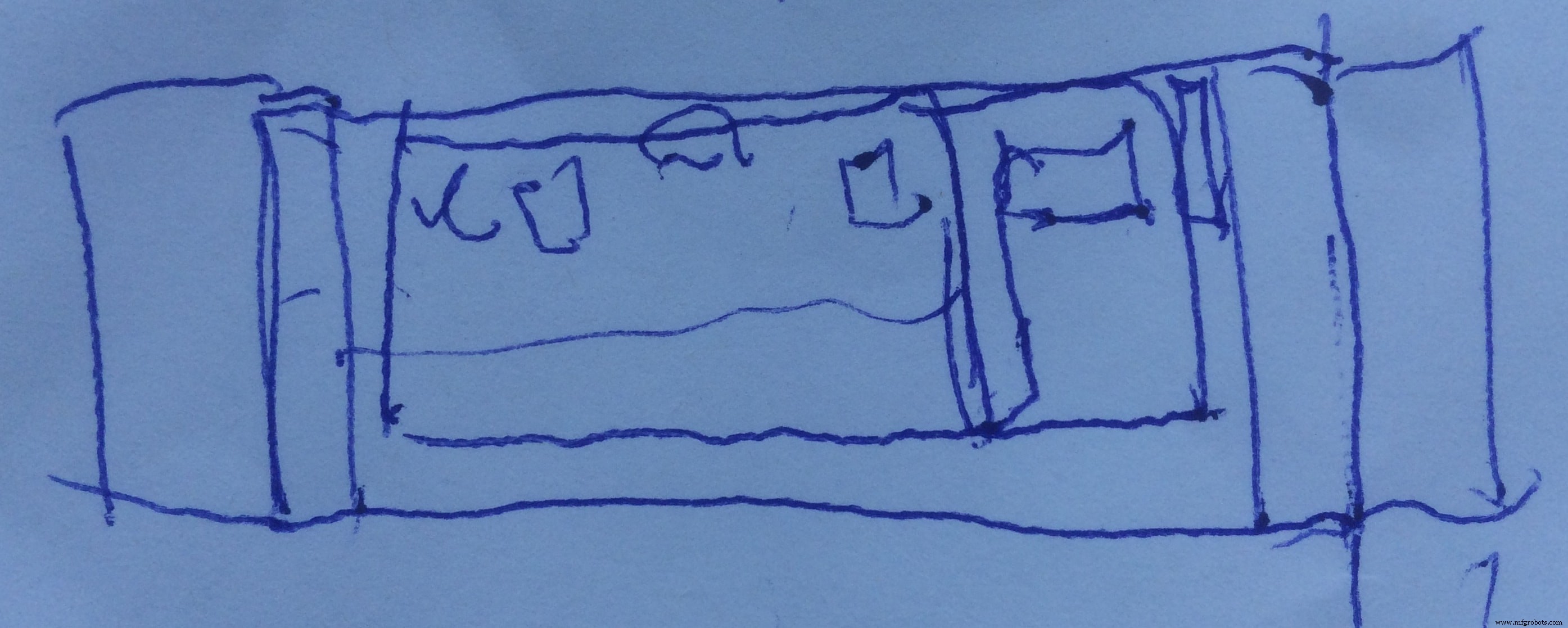
Before designing it in the digital world, I made a simple sketch on paper! Here it is:
And this is the final 3D design:
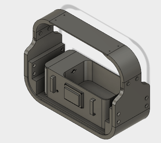
My sexy ass system :D
First thing which I designed was the water container . Here it is:
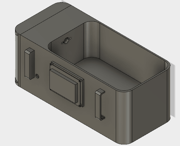
It incorporates several features! First, there is enough space for plants to grow, as well as in the middle I made a hole to place the Ultrasonic Atomizer. It is done because I wanted to level the fogger with the container. The thing is that the water level should be above the fogger by 2cm, so all the water which is leveled with the fogger hight, will not be used (waste)! So if I place the fogger below the container level, I have a water zero level exactly at the point where it should be, zero for the container =2cm above the fogger. In this way, all the water is used!
I also considered the hight of the container. Actually, all the dimensions of the container are measured during the experimental stage!
As you can see, I made a hole on the wall, which will be used for the cables from sensors placed in the water to hide into the electronics section. In the front of the container, I made the slot to attach the graphic display. I also designed some handles to easily remove the container when need!
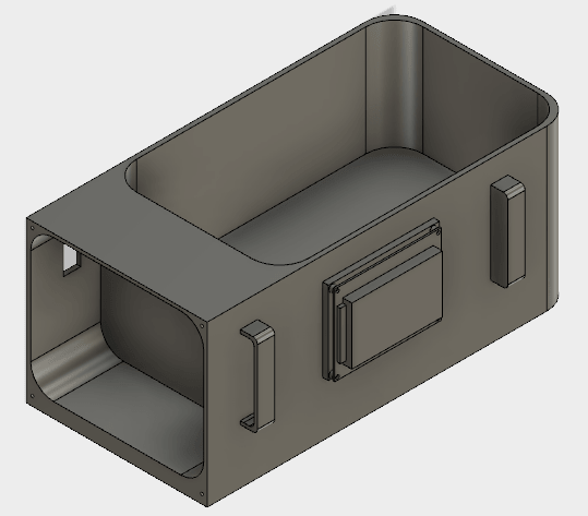
From this perspective, you can see the electronics section. Now its opened, but I also designed a lid to close it. Inside the electronics section, I designed a hole to have access to power and program the board
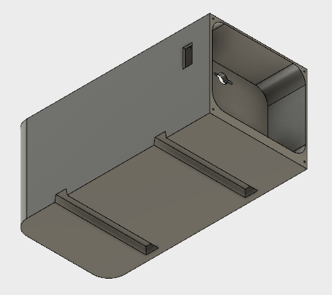
On the bottom side I designed sliders which will be attached to the rest of the system, and make it easier to remove the container when needed, it will also play a role of fixation of the container in place!
And now Let's Print It!
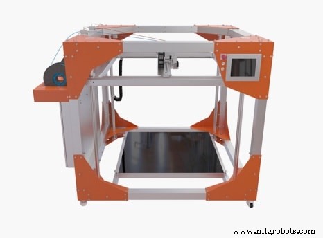
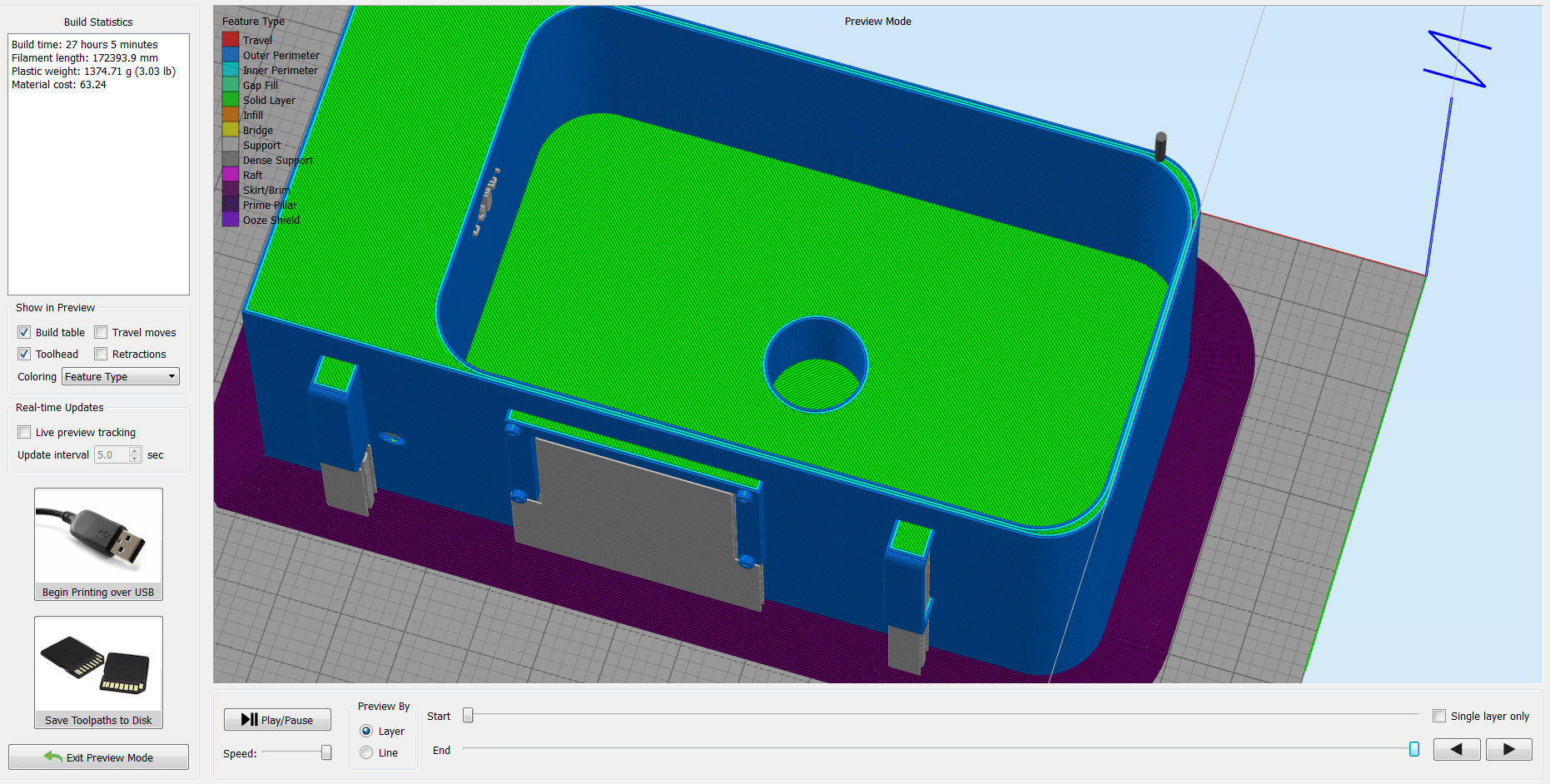
I can proudly announce that the printer which I will be using is called BigRep 3D Printer , only available in our FabLab Kamp-Lintfort. It has a capacity of one cubic meter, and provides the largest FFF build volume for professional and industrial use.
The slicing software which I use is Simplify3D , one of the most advanced slicing tools, in my opinion, with a lot of configurations and options.

I do not think that there is a right and a wrong way to print something, you just have to play with the settings until you find the best options for the specific object to print.
Because this printer is new, there are not too many testings made. So, I had to experiment with the settings, and try, try and again try...
I will show bellow the settings that I will be using for my water container print, but some of them are intuitive.
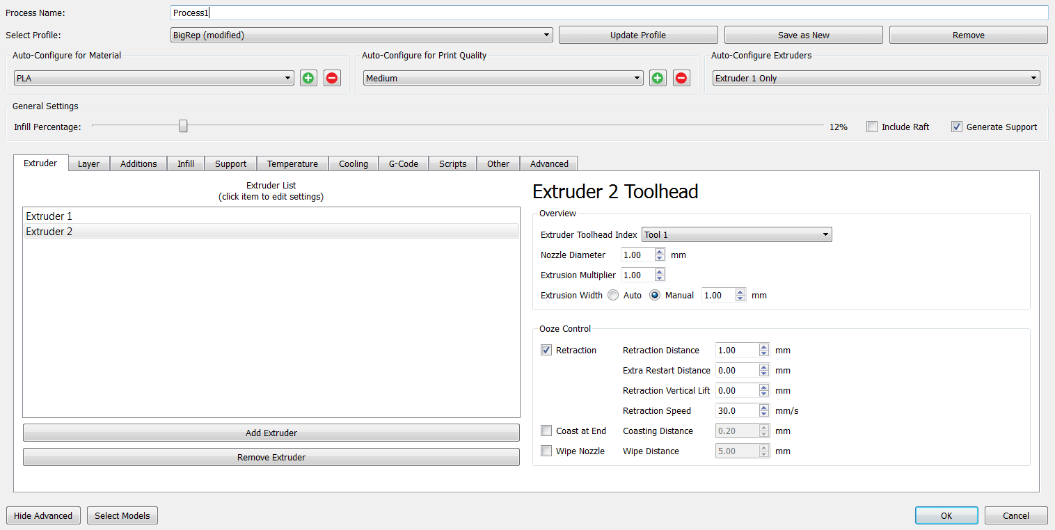
I choose the Tool1 , because the BigRep Printer has two nozzels with two different filaments, and I have to specify which nozzel I want to use, as well as the nozzle diameter and the rest of the settings.
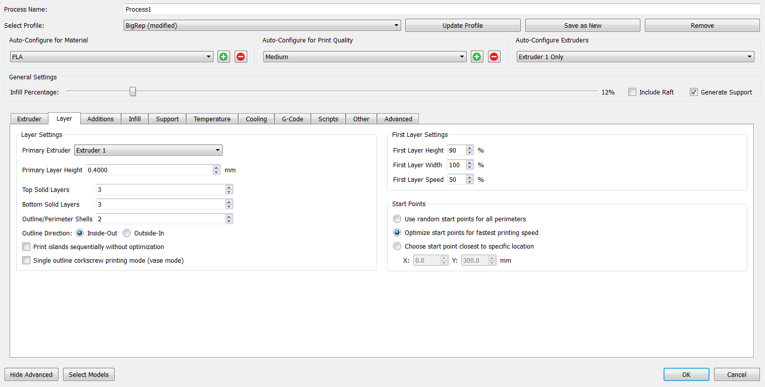
Layer:
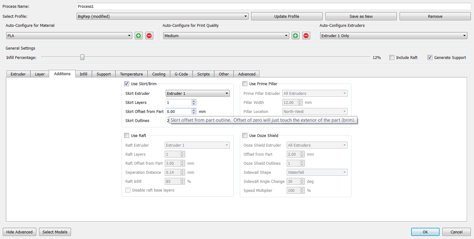
Additions:
Infill:
Soporte:
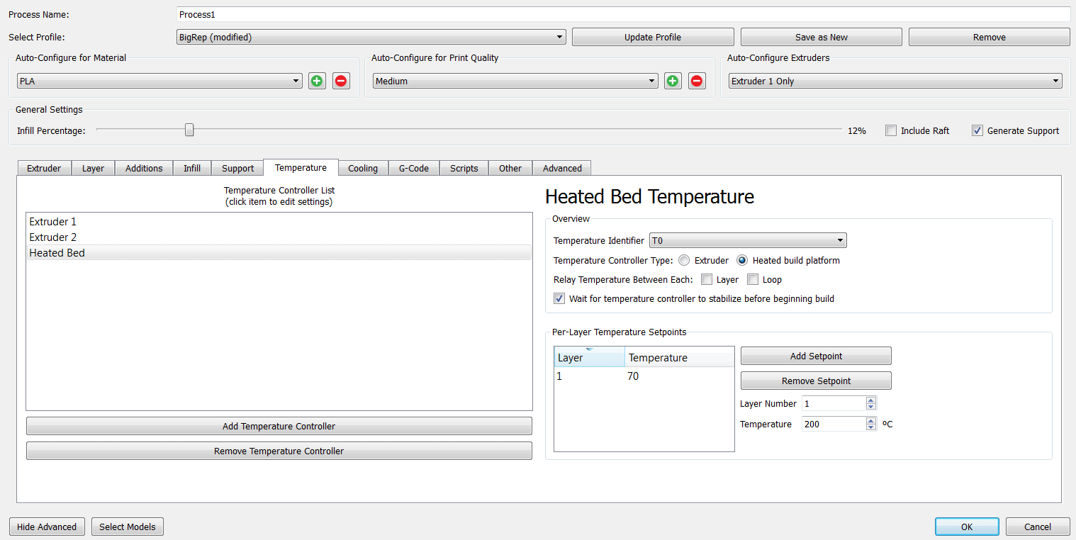
Temperature:
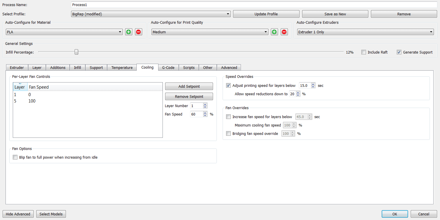
Cooling:
Other:

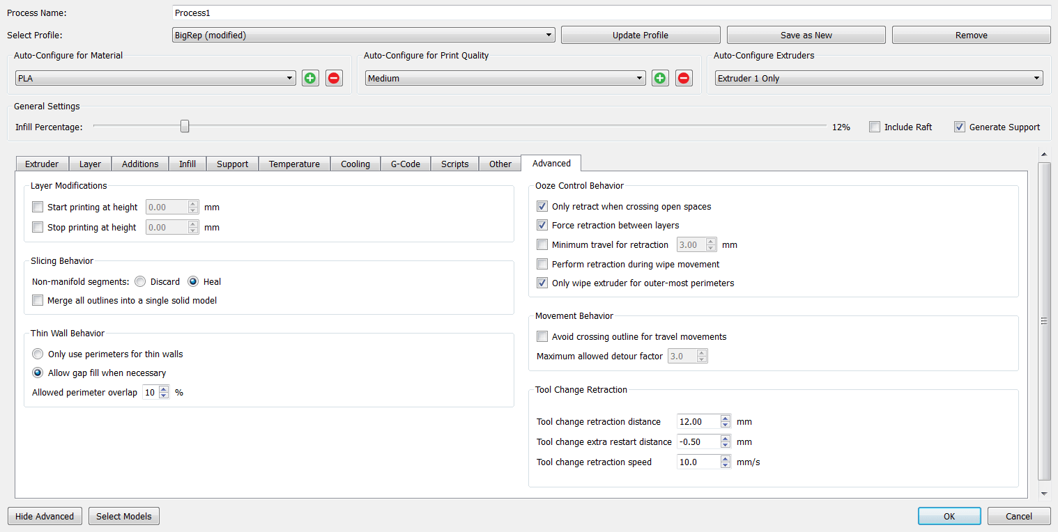
Advanced:
These are the changes that I made, the rest of the settings I just left by default.
And then press on Prepare to Print . The software will generate the paths, and here we can check if everything is good, before sending the .gcode to the maschine.
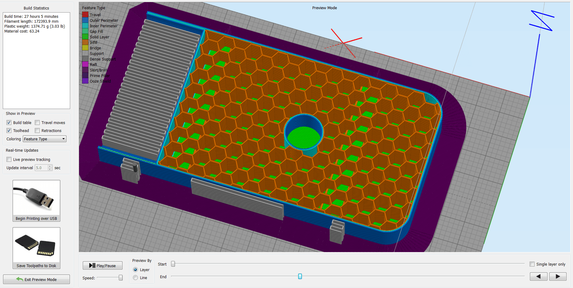
Briefly about some of the printer's settings. I used Nozzle Temperature =205 deg.C , and the Bed Temperature =70 deg.C . After I positioned the X, Y, and Z axis , and double checked all the settings, I launched the job!
This is how the raw model looks like:
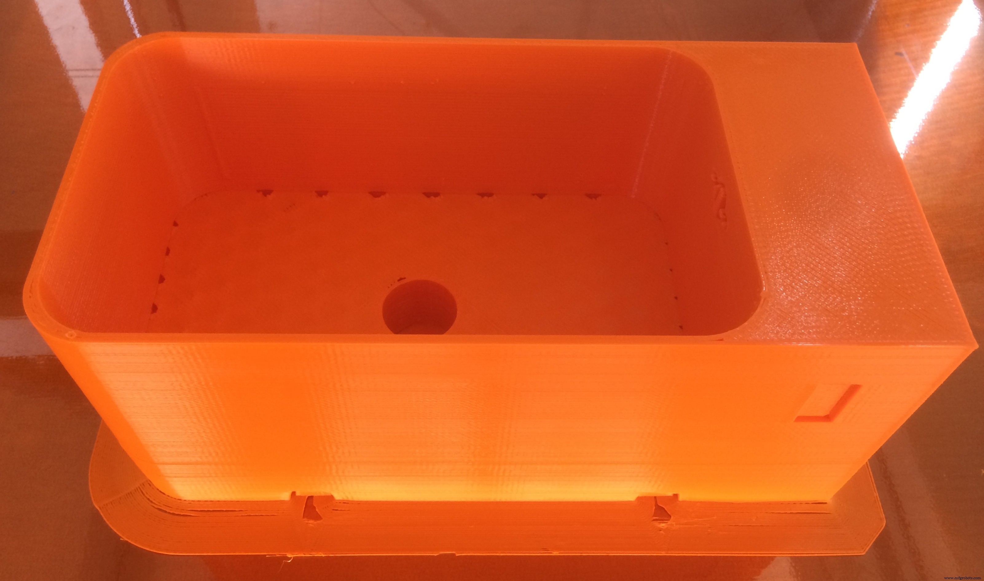
When I started removing the support and cleaning the model, I realized that this is a BIG pain in the ASS :D
As you can notice, the settings which I used are not really perfect, because the container has some big holes next to the edges. I had in my mind to waterproof it anyway, you can see how I did it in the Moulding &Casting section!
The next 3D printed part was the Net Pot . This is a cup which is designed to hold the seeds in the growing medium. More detailes about the first version of them you can see during my Computer-Aided Design week
This time I will improve the design a bit based on the observations that I made during the experimental stage. The main difference is the size of the empty space, which is increased a lot, to give an easier access for the fog to pass in, and for the roots to go through
So I just modified the old design, and added one more thing!
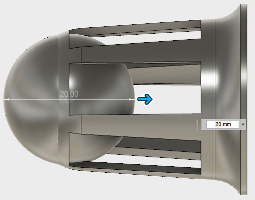
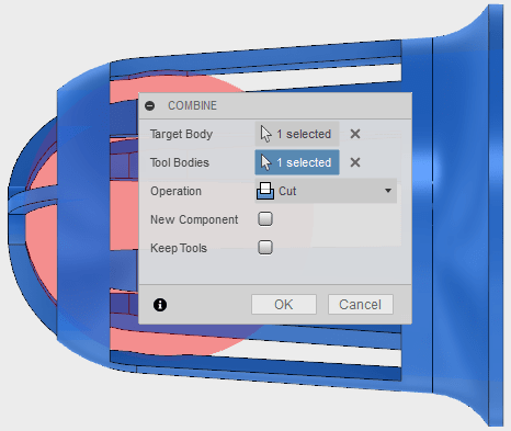
I made a slight fillet on the top part, to make the transition smoother. I also added a ball on the bottom, and used the Move command to move it a bit inside, and leave on the bottom around 2-3mm structure width
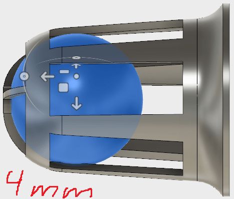
After I used the boolean substraction or Combine function, and I get this nice curviture at the bottom!
Now let's print it!
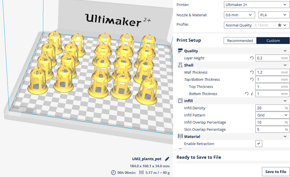
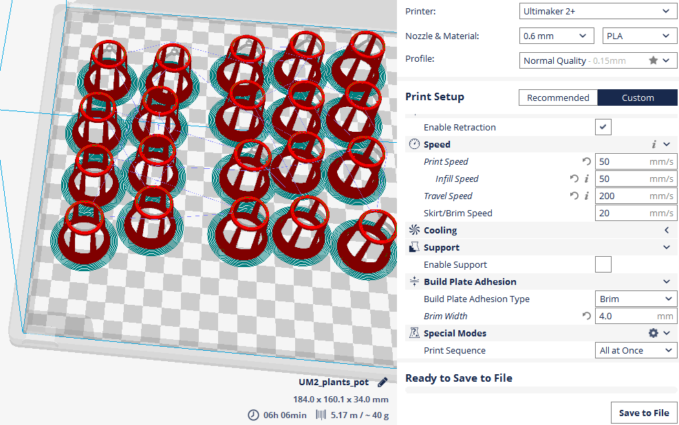
The 3D printer which I used is Ultimaker 2+ . To slice my 3D model, I will use, a very nice software, with an easy interface, and also functional. The material that I am using is PLA filament

After I import my .stl file, these are the settings that I am using:
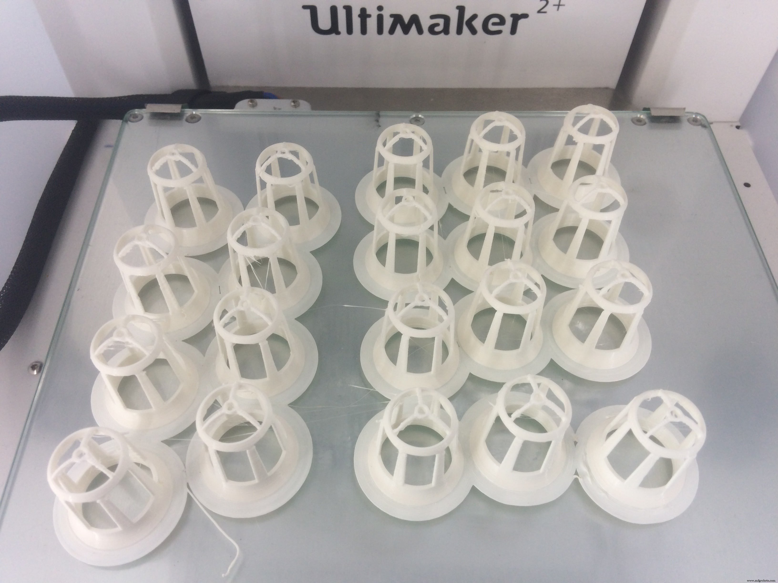
Here it is my little army :D
From the final design of the system, I decided to also 3D print the bottom part. Its a big piece, and I will use the BigRap as well for this.
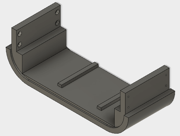
I wouldn't say that there is anything new about this, because I used the same settings as I used for the water container , and more or less the rest is the same
Here is the preview of the print:
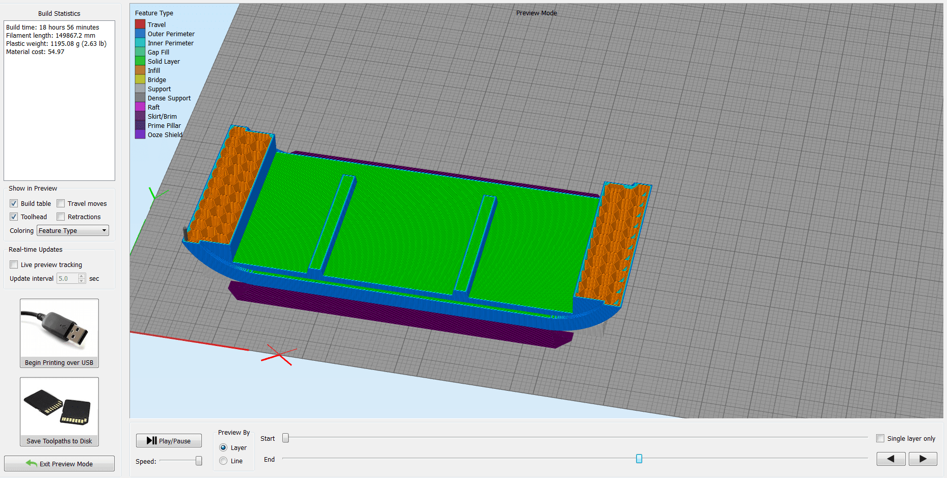
Another thing which I 3D printed are the rounded corners on the top side of the system. I used the Ultimaker for this, and used the following settings:
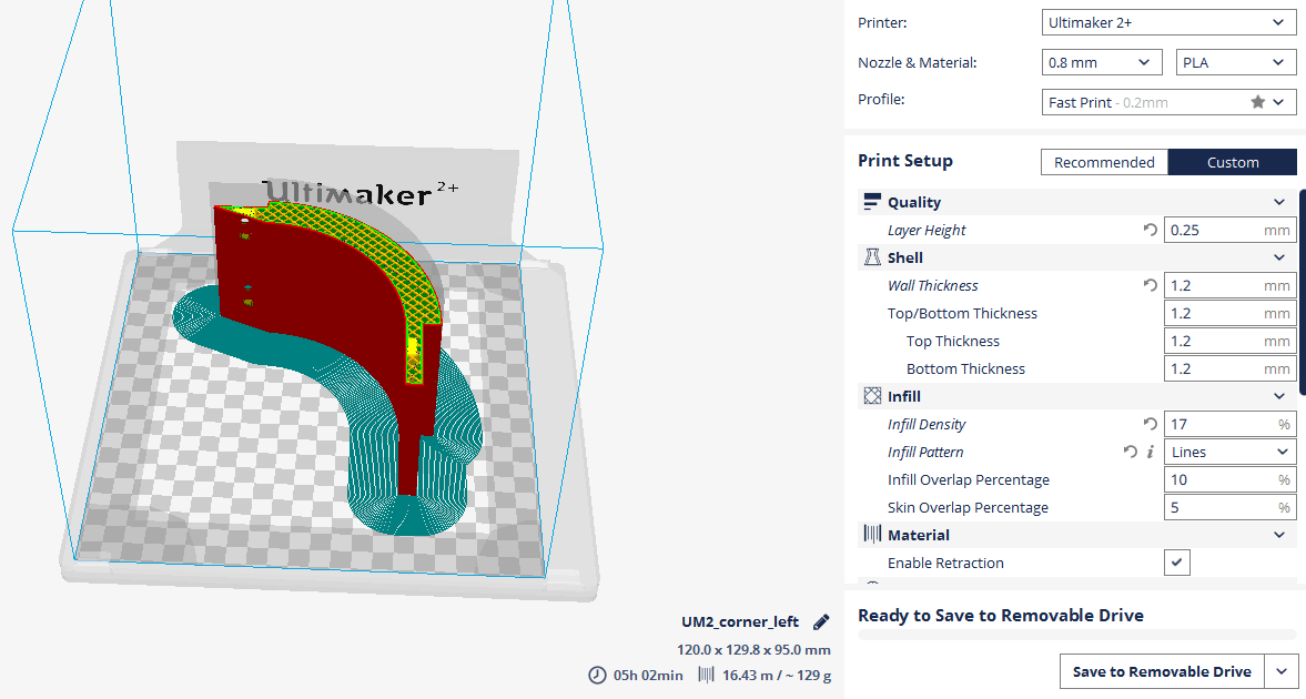
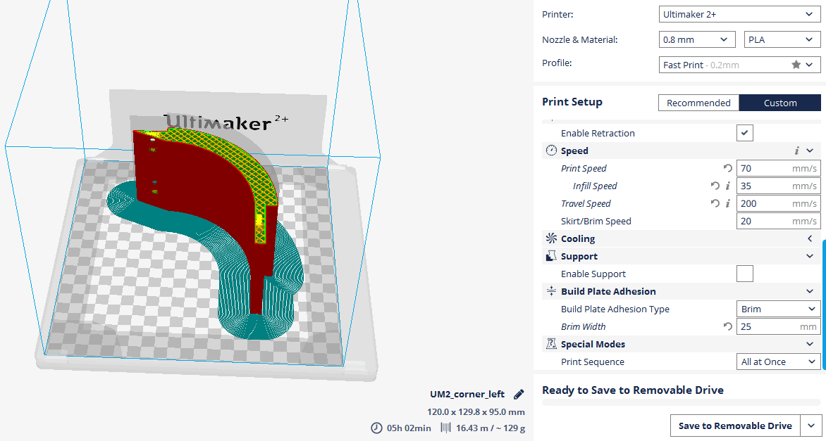
The trick here was to achieve maximum smoothness on the surface, and I think I got a pretty good result:

Download Files:
GIY System Design (.f3d)
Net Pot Design (.f3d)
2D Design &Laser Cutting
I used the Laser cutting technique to cut acrylic parts which will cover all the inside part of the system, and give it a finished look!
I actually did not design the parts again, I just exported the already created sketches from Fusion 360 as .dxf files . After I exported the file, I used to edit the design before importing it into the lasercut machine

This is how the sketch looks in Fusion360:
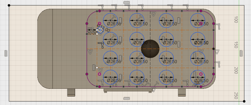
Looks like a big mess, but the good part is that everything is parametric! It looks messy because I had to align everything into the right position, and keep the stuff parametric in case I have to make a change later
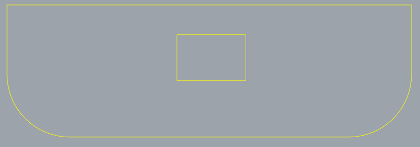
This is how the final sketch looks in Rhino before lasercutting:
I decided to use a green acrylic piece because it gives an organic look, and combines well with the green plants
For the front and the back cover, I decided to use white color. Its all about the taste, this is the way I see it, and this is how I like it.
The front and the back cover are very similar, have the same dimensions, except the inside cuts! The front cover has the hole for the LCD Display, here it is:
For the back cover, I want to make a hole to have access to power and program the board! This is how it looks:
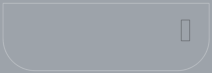
Another lasercutted piece is on the top! I decided to use a transparent acrylic part, in order for the light to go through! I also designed some additional cuts, to decrease the weight, and give more space for the light to pass! I also measured the width of the RGB LED stripes, and will attach them in a way that there is enough room for the sunlight as well as artificial light!

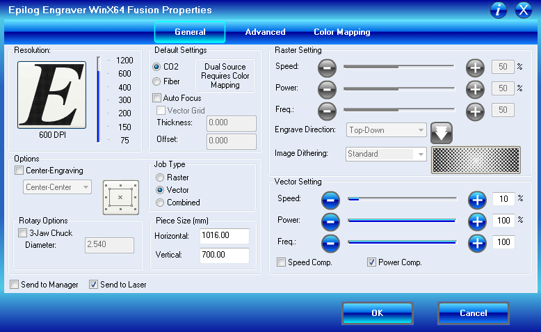
I finished with the design, and now Let's Laser Cut!
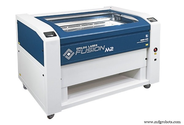
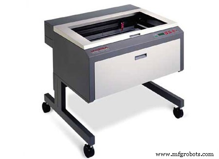
The Laser Cutter that we are using here in FabLab is Epilog Fusion 60Watt, a CO2 lasercutter with a working area of 1016 x 711 mm. It can cut and ingrave materials like wood, cardboard, acrylic or other engineered plastics.
Because I used the same material for all the pieces, plexiglass 5mm , I used the same settings for all of them!
Download Files:
Front / Back Cover (.dxf)
Plant Holder (.dxf)
LED Light Holder (.dxf)
CNC Milling
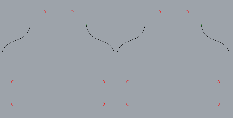
Because I wanted to integrate in my system all the skills and techniques that I learned, I also have a piece of structure to CNC mill. I did not design it again, but I exported the .dxf file from Fusion360 sketch!
To cut my design, I will be using the big CNC monster.
A CNC (computer numerically controlled) is a machine that uses a cutting bit that rotates at a very high speed to remove material from a part.
The machine reads a pre‐programed computer file telling it where and how to cut, usually .GCode Archivo. A cutting bit is rotated at a very high RPM by a spindle motor, which can move the bit up and down. This mechanism is moved left, right, front, and back by a cross arm. The machine is therefore known as a three‐axis router because it can move on the X, Y &Z axis. The machine can do two dimensional cutouts and etching, as well as three‐dimensional relief work.
In FabLab Kamp-Lintfort we have a CNC portal milling machine by e(sign:Easy Worker MasterPro 2513.
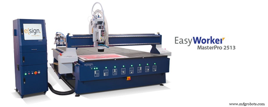
It’s working area is 2600 x 1400 x 300mm and it comes with a vacuum table. We primarily use it for wood milling but with its HSD Spindel (3.9KW; 24.000U/min) it is also capable to mill metals easily.
The material which I will be using is 18mm Plywood
At first, I place the wood sheet on the CNC bed, and after I aligned it, switch on the vacuum. After I exported the .dxf file, I used to edit the design before importing it into the machine CAM software.
First, I have to HOME the machine!
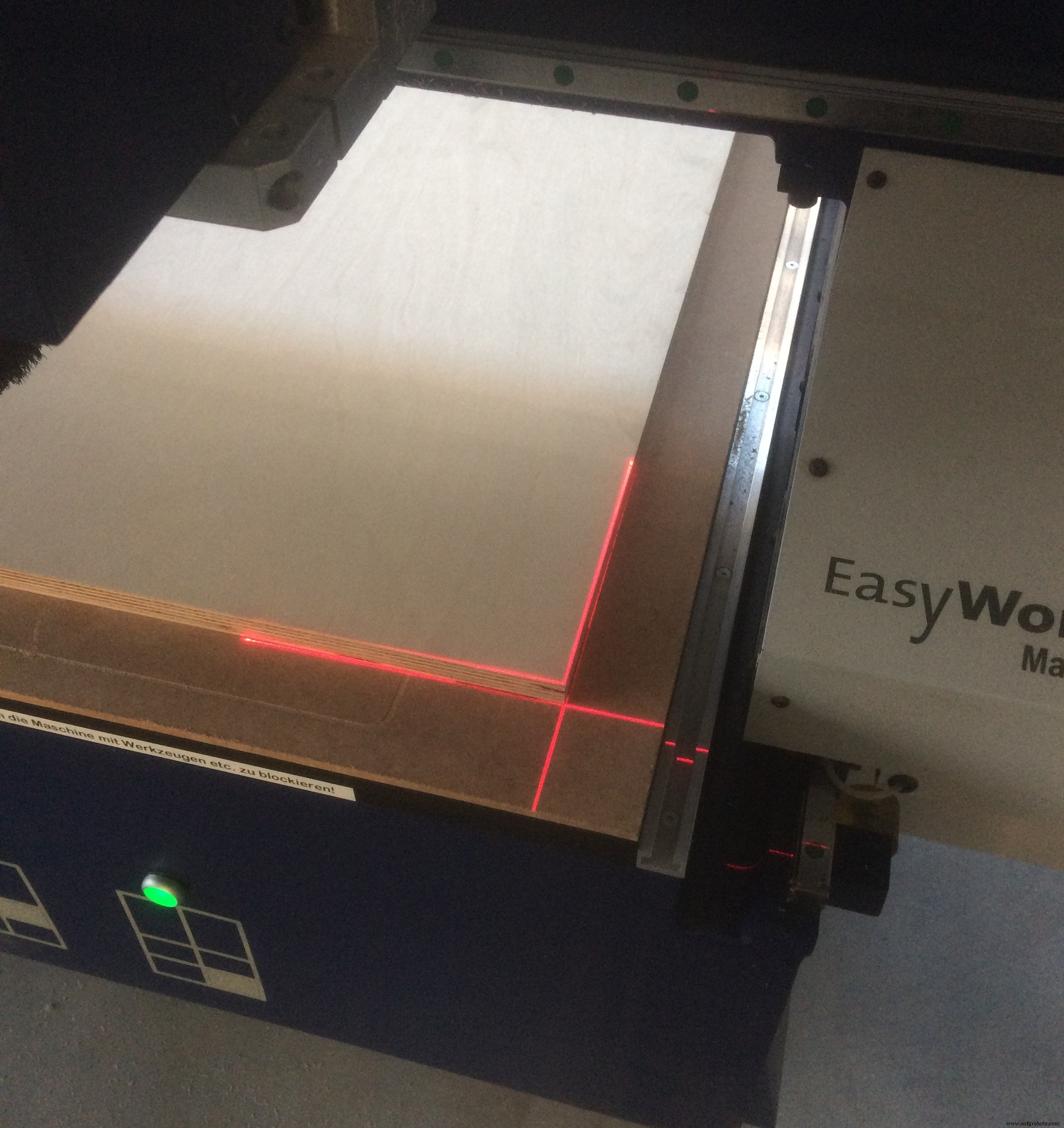
To set the X, Y and Z Zero Positions, I home the machine by pressing the home button in the software (or on the remote control).
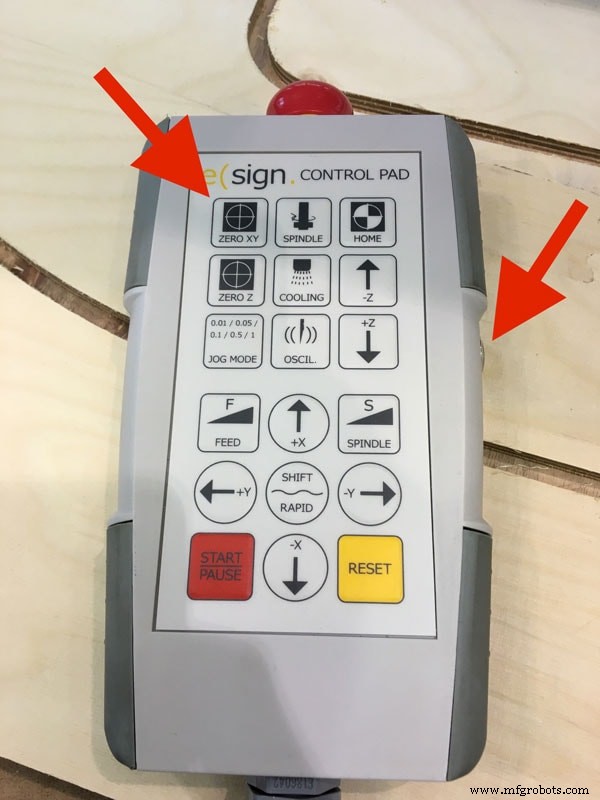
At first, I can set my zero X and Y roughly aligned to one of the corners of the bed. We also tried to use the laser for this, but all the time when simulating the process, it was showing collisions, because the zero was going out of the working area
Now I have to find the Z axis, which I do using the special tool which comes with the machine:
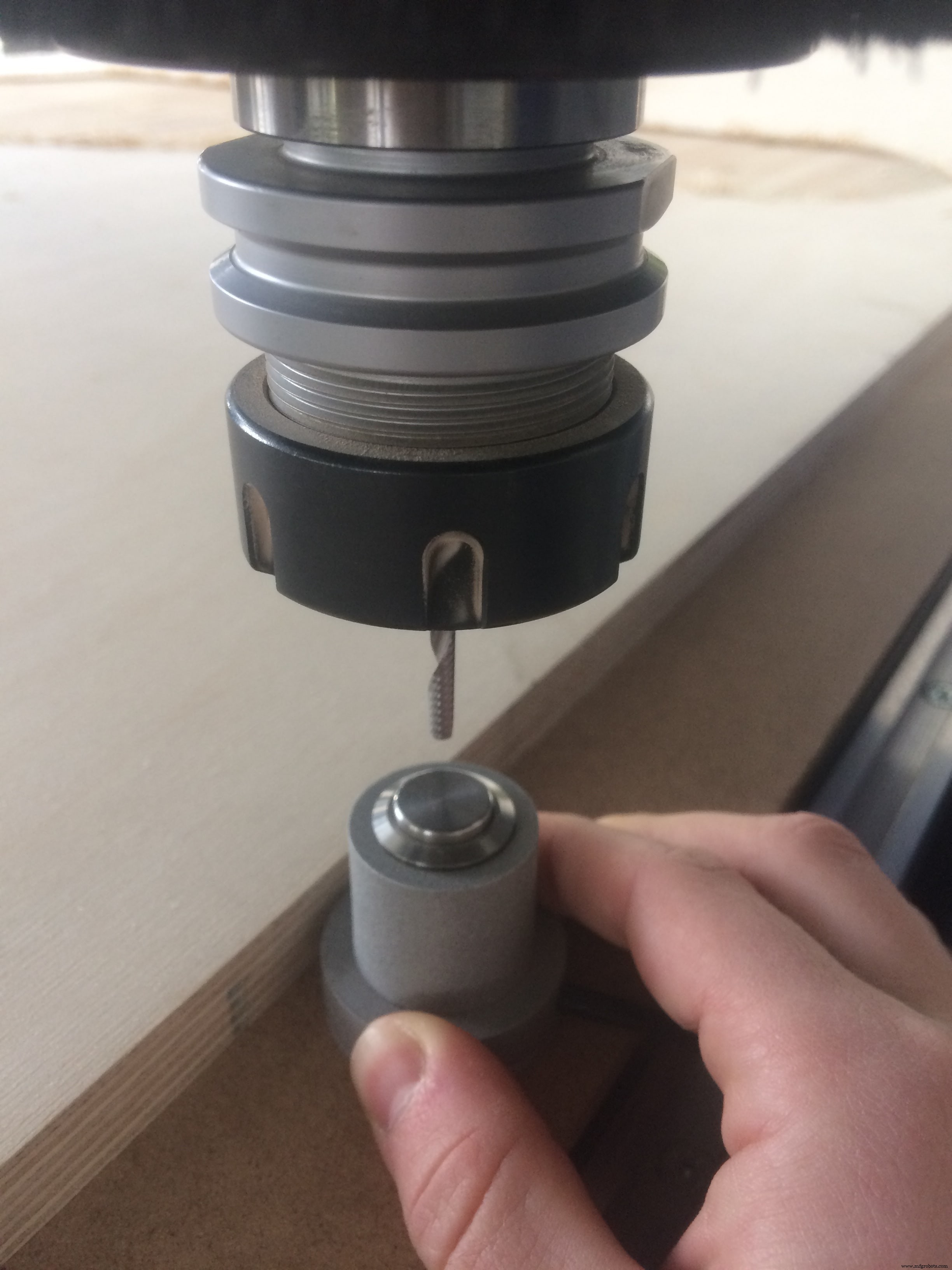
Important thing is to place it on the bed of the machine!
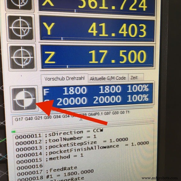
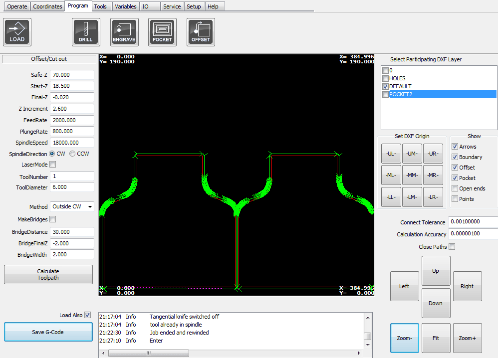
Now I can launch the first job, which is making the engraving. These are the settings which I used:
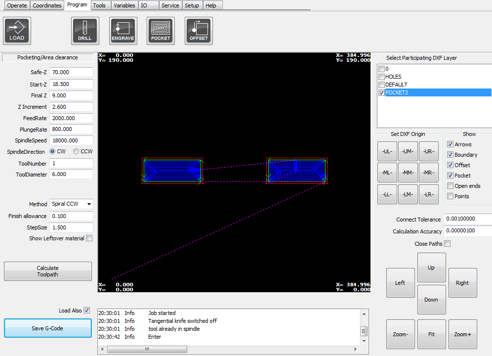
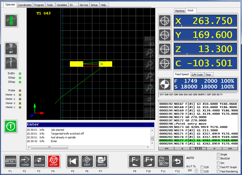
I press Calculate Toolpath to simulate the job and make sure that there are no collisions! After I save the .GCode , and launch the job, I get this window:
Now I can launch the outside cut:

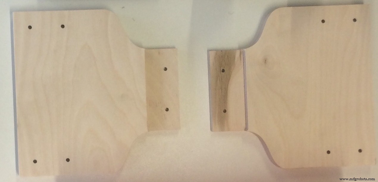
This is what I get after the job is done:
Another piece which I had to mill is used for the Moulding &Casting section!
I prepared the mould to waterproof my water container. Here is the design:

There is nothing new about this. I used exactly the same settings as above. The only thing is the material thickness was 10mm wood , and I had to cut 7 pieces, to glue them together later and prepare my mould!
Download Files:
Structure Walls (.dxf)
Mould (.dxf)
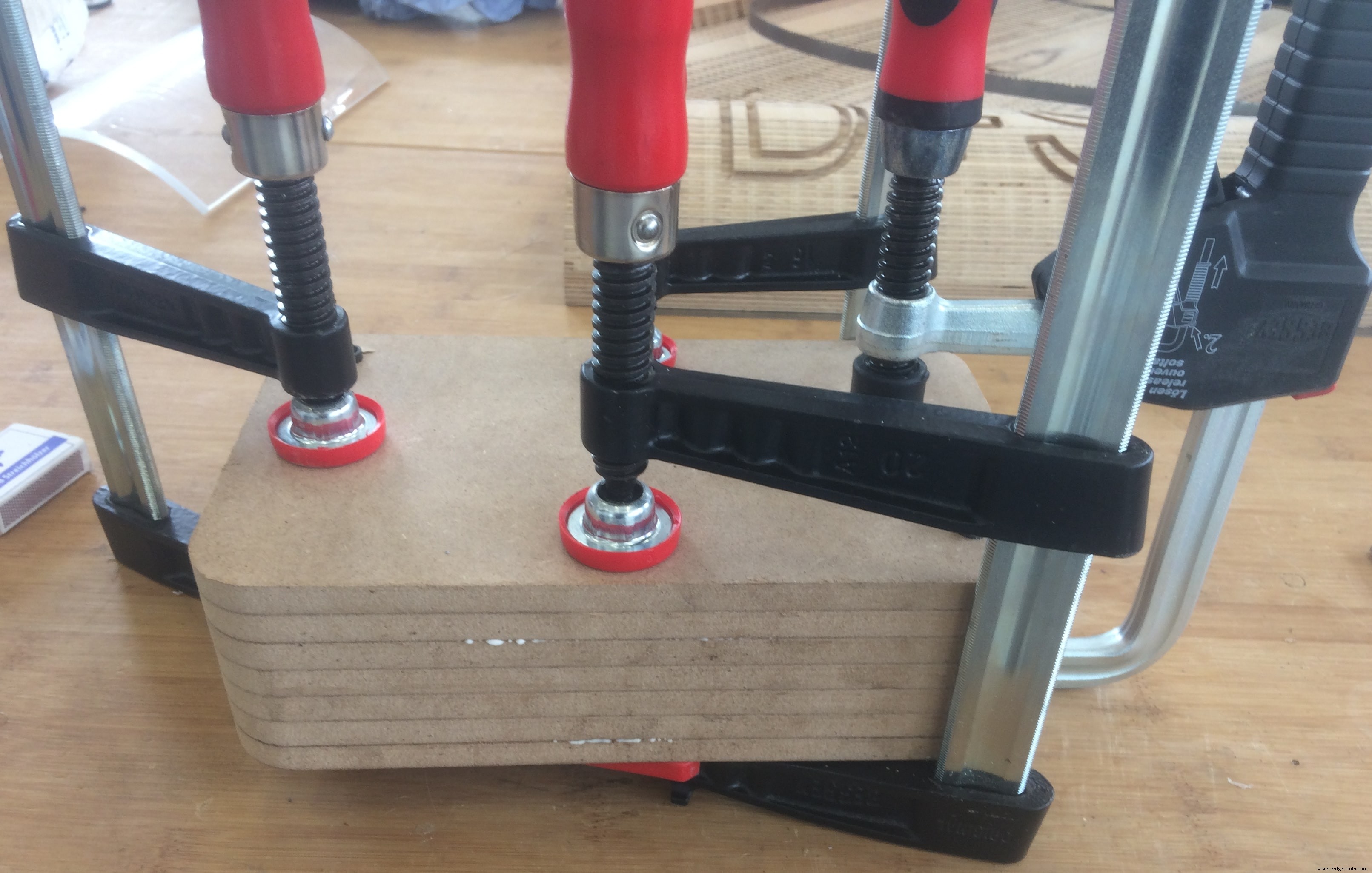
Moulding &Casting
I used this technique in order to prepare a water container, to waterproof my existing container! I see it as a thin layer of material (a smaller container) which can be easily removable!
This is the result from the previous section CNC Milling
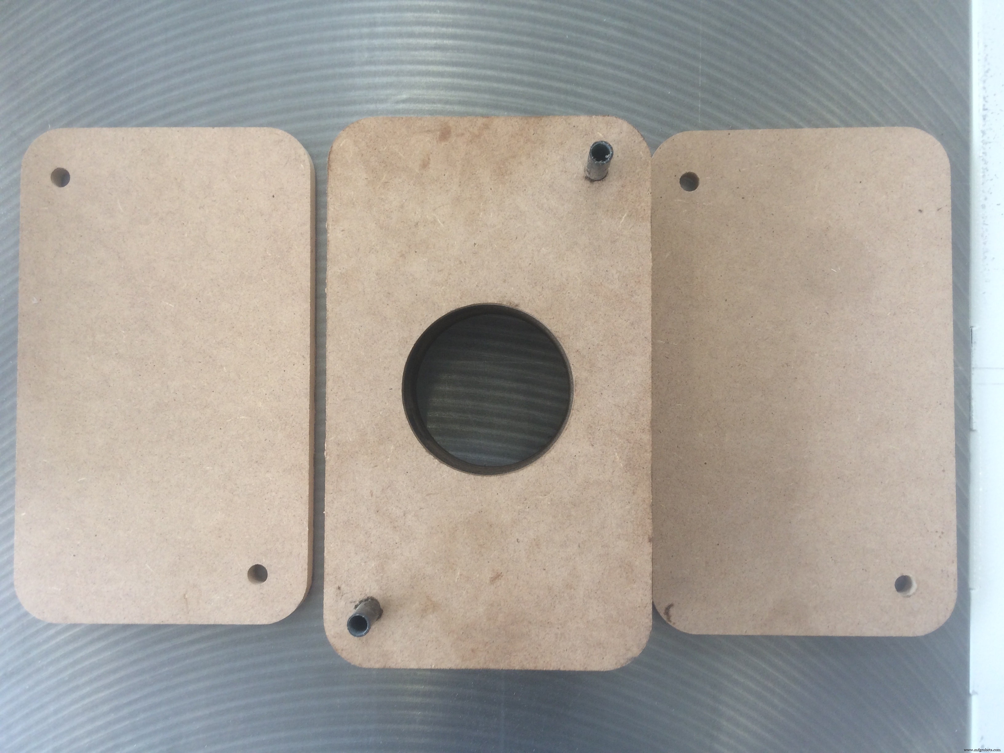
I cut 7 identical pieces, and aligned them using the reference holes! I also cut a big hole in the middle of 5 bottom pieces , in order to place the air pump inside, and easily remove the cast later.
After I glued all the pieces together, and fixed them, this is how it looks:
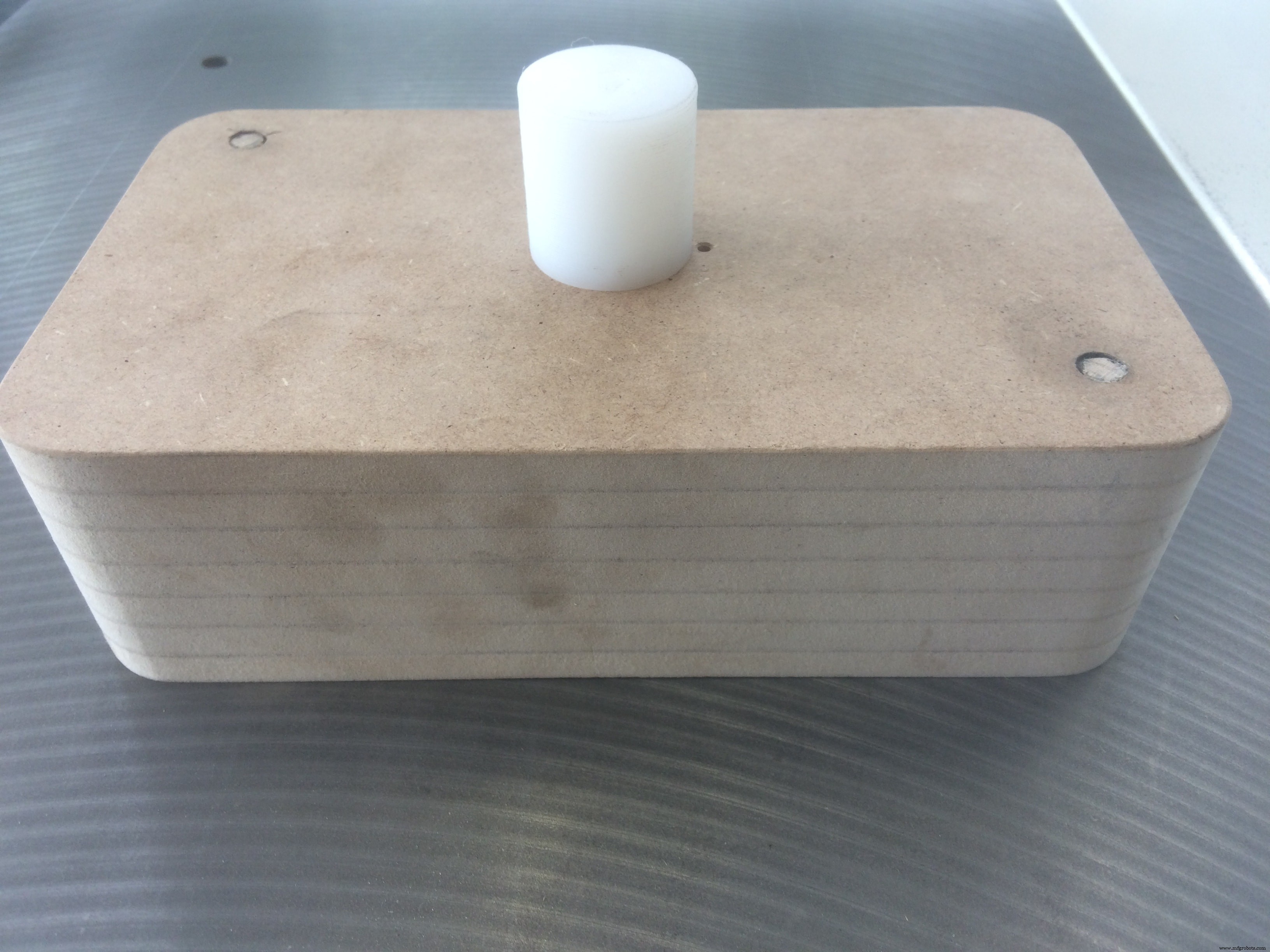
While waiting for the glue to dry out, I prepared a little plastic "thing" (do not know how to call it :D) for the pump. The idea is to be able to screw it on my mould, and remove it whenever I want!
When the mould is ready, this is how it looks:
And the back side:
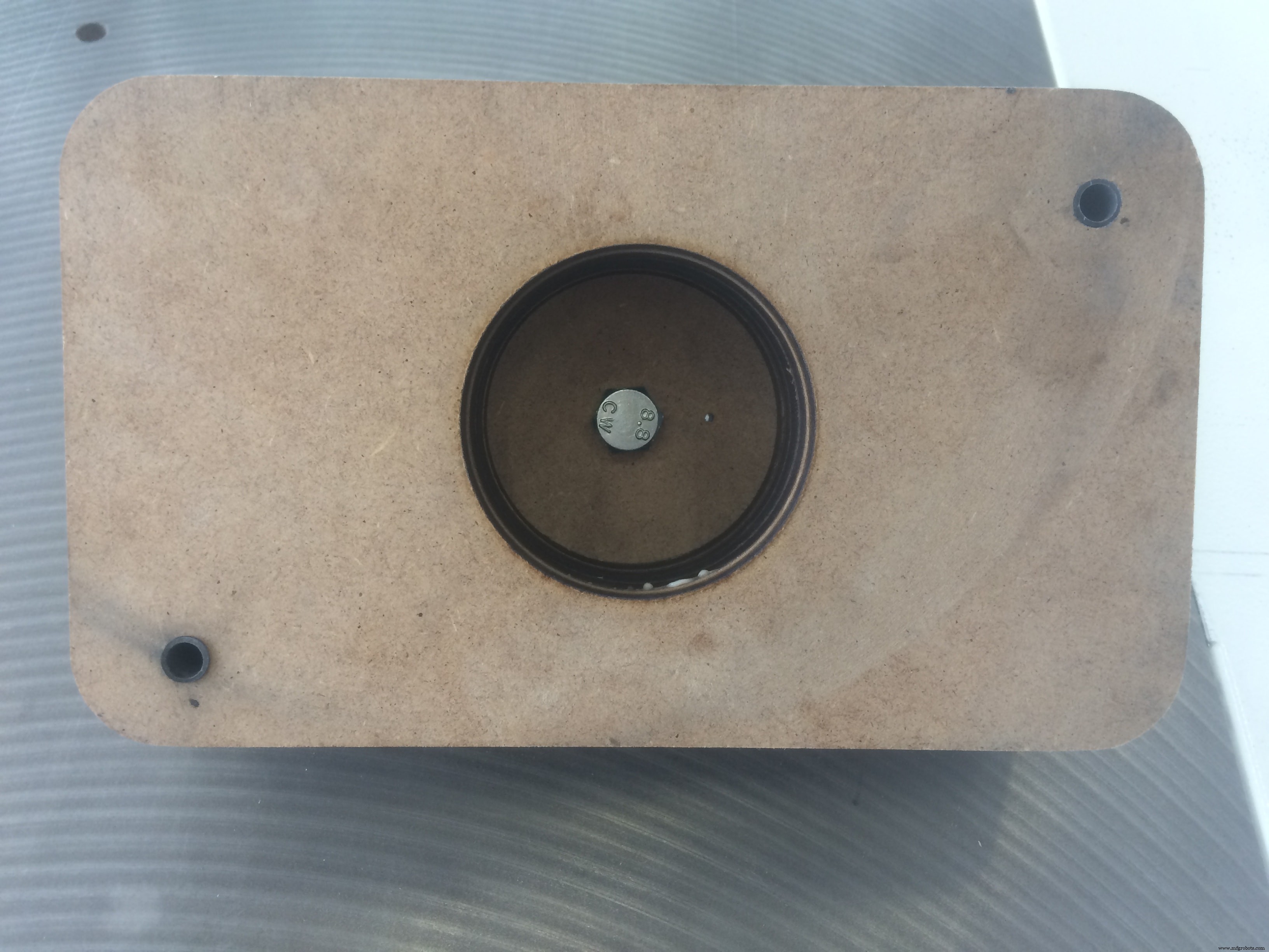
I am ready to vacuum cast!
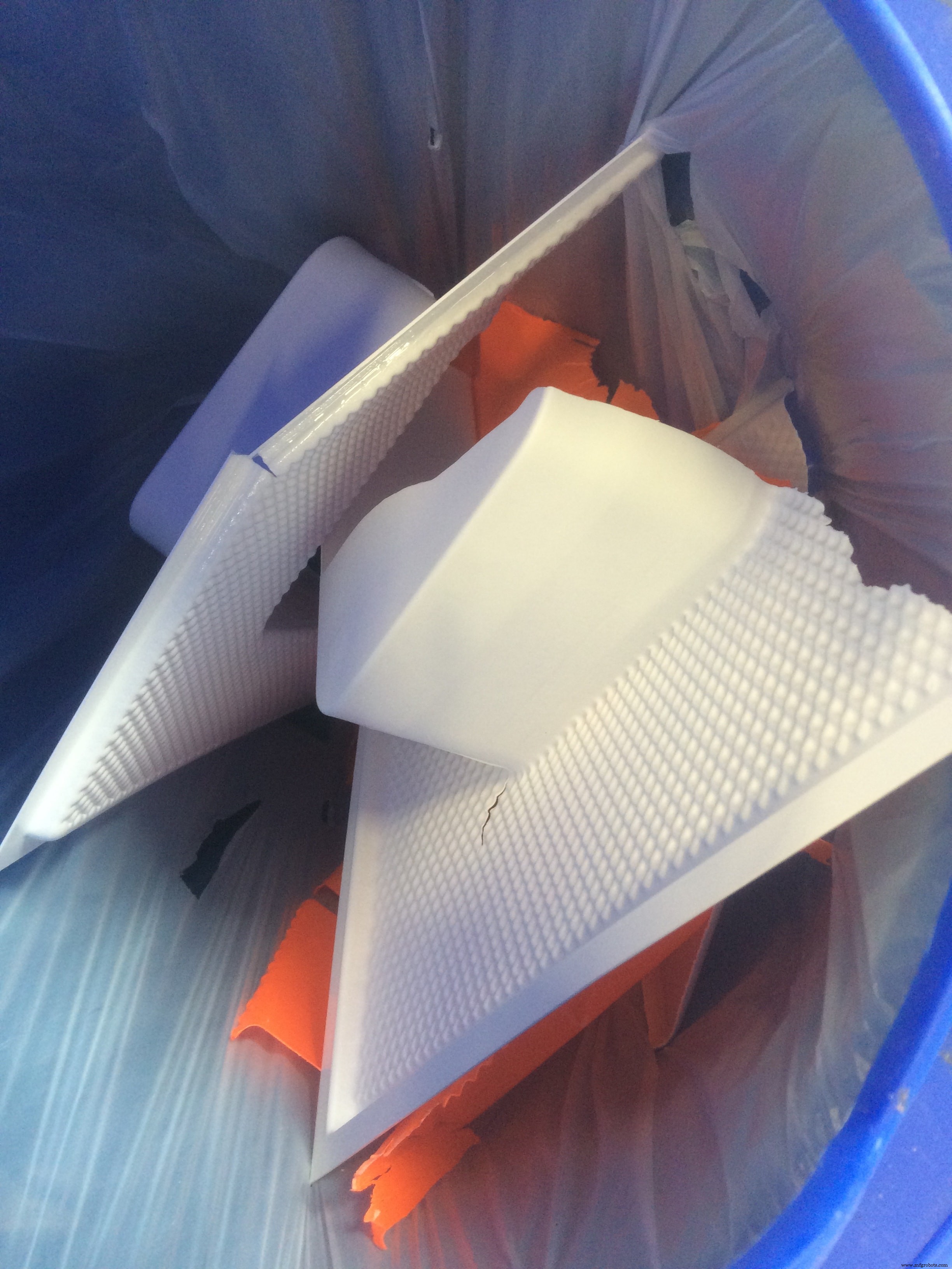
I used a vacuum machine available in our FabLab Kamp-Lintfort called Formech – Manual Vacuum Forming Machine
The thing is that I tried to do it many times, and all the time I could not remove the mould without breaking the cast! After several hours of trials, I came up with a solution! First, I vacuum casted one thin layer of material, and without removing it, I will cast the actual container on top of it. The first thin layer is slippery, and If I spray it with silicon, it will allow me to remove the mould way easier
After I let the silicon to dry a bit, I can cast the actual layer!
And here we are!!!
A hero shot for those who may thing that it was easy
Putting All Together
Now, let's put everything together! I will start by assembling the structure. Put next to me all the necessary tools:
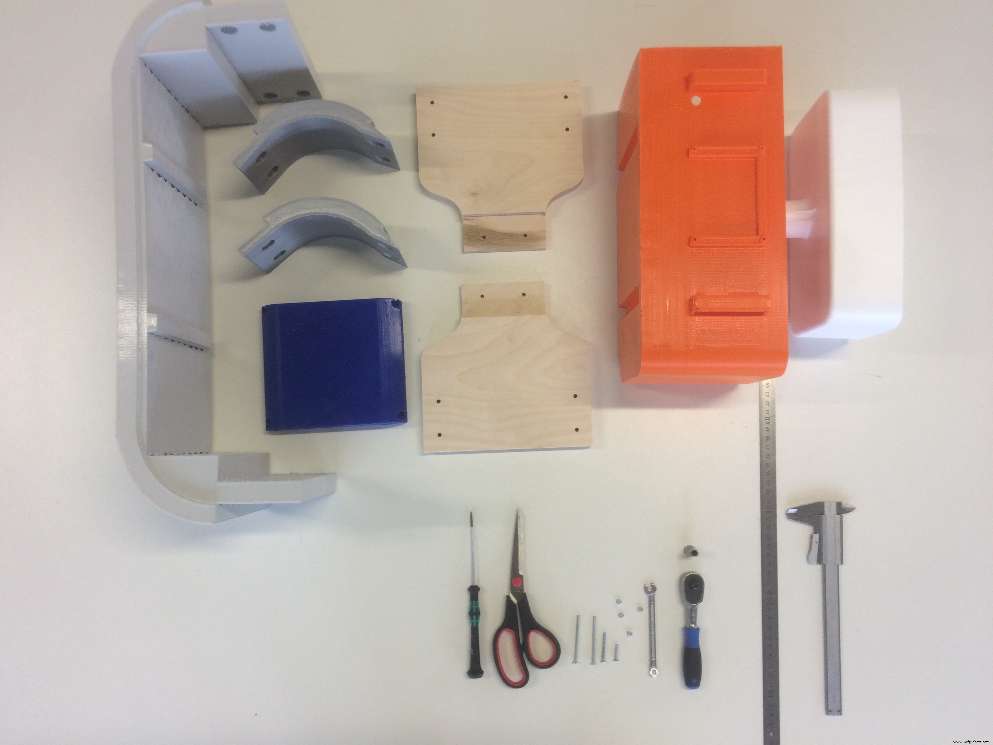
A short animation of the process:
To assemble the lights, I cut the RGB LED stripes into 4 pieces (I measured the length in advance), and soldered them accordingly!
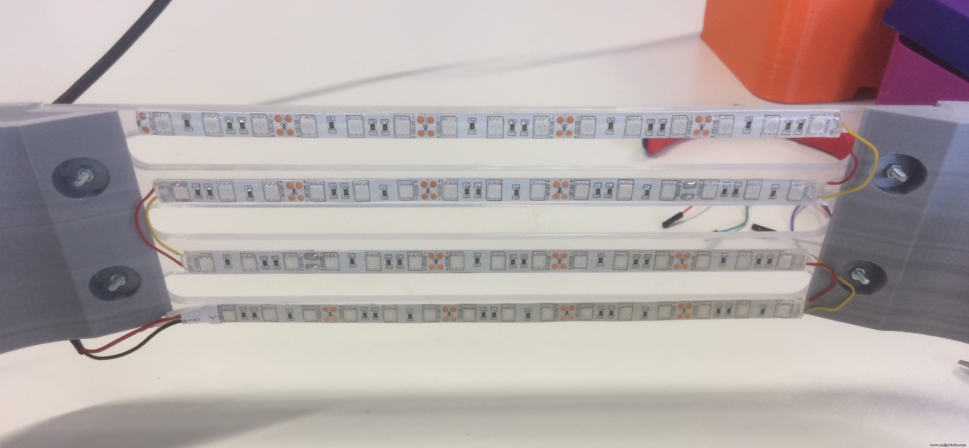
After I connected all the sensors, and managed the wiring, I fixed the board in the electronics section
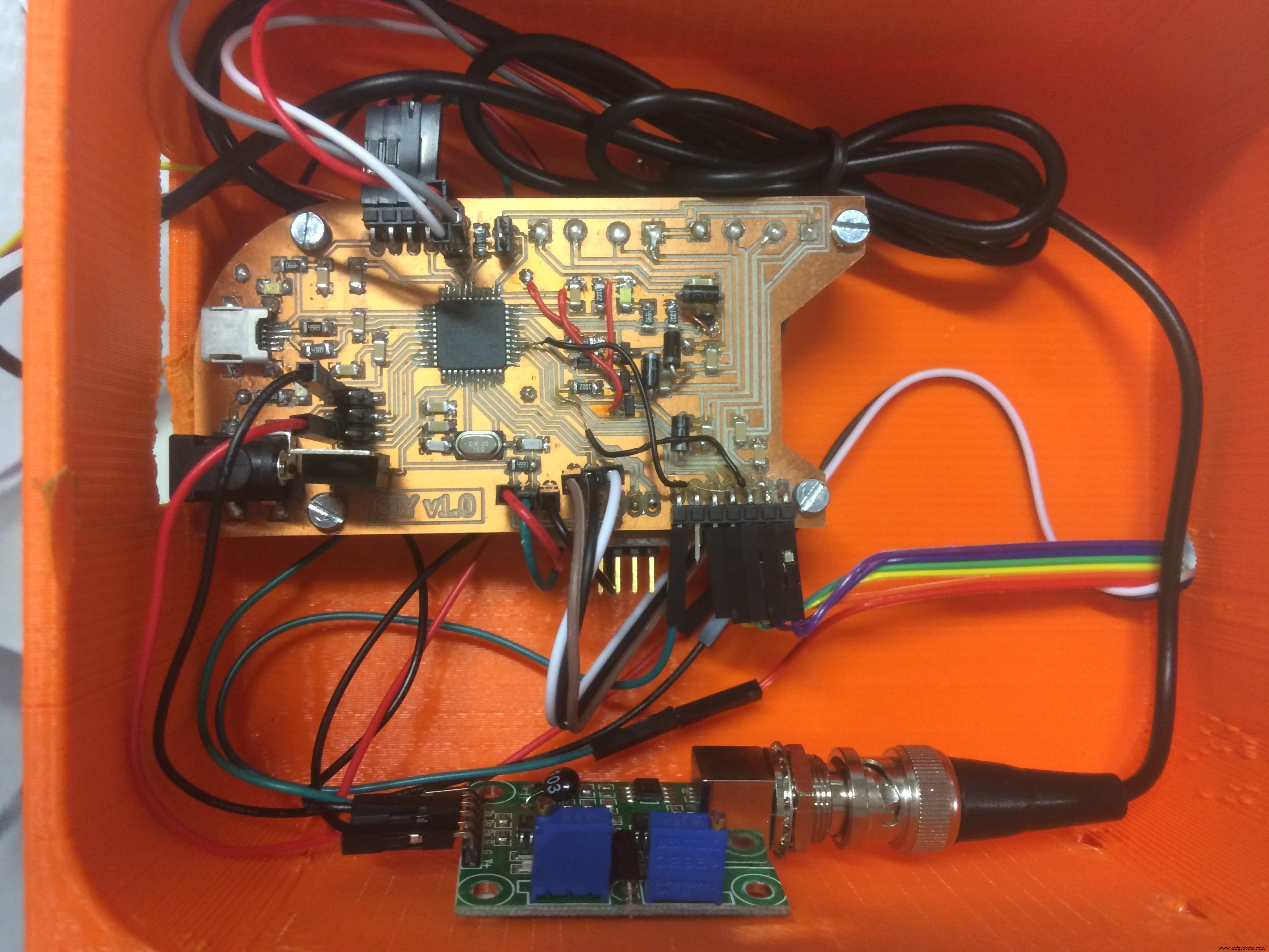
And here it is the system!!! Everything assembled, nice looking growing system GIY
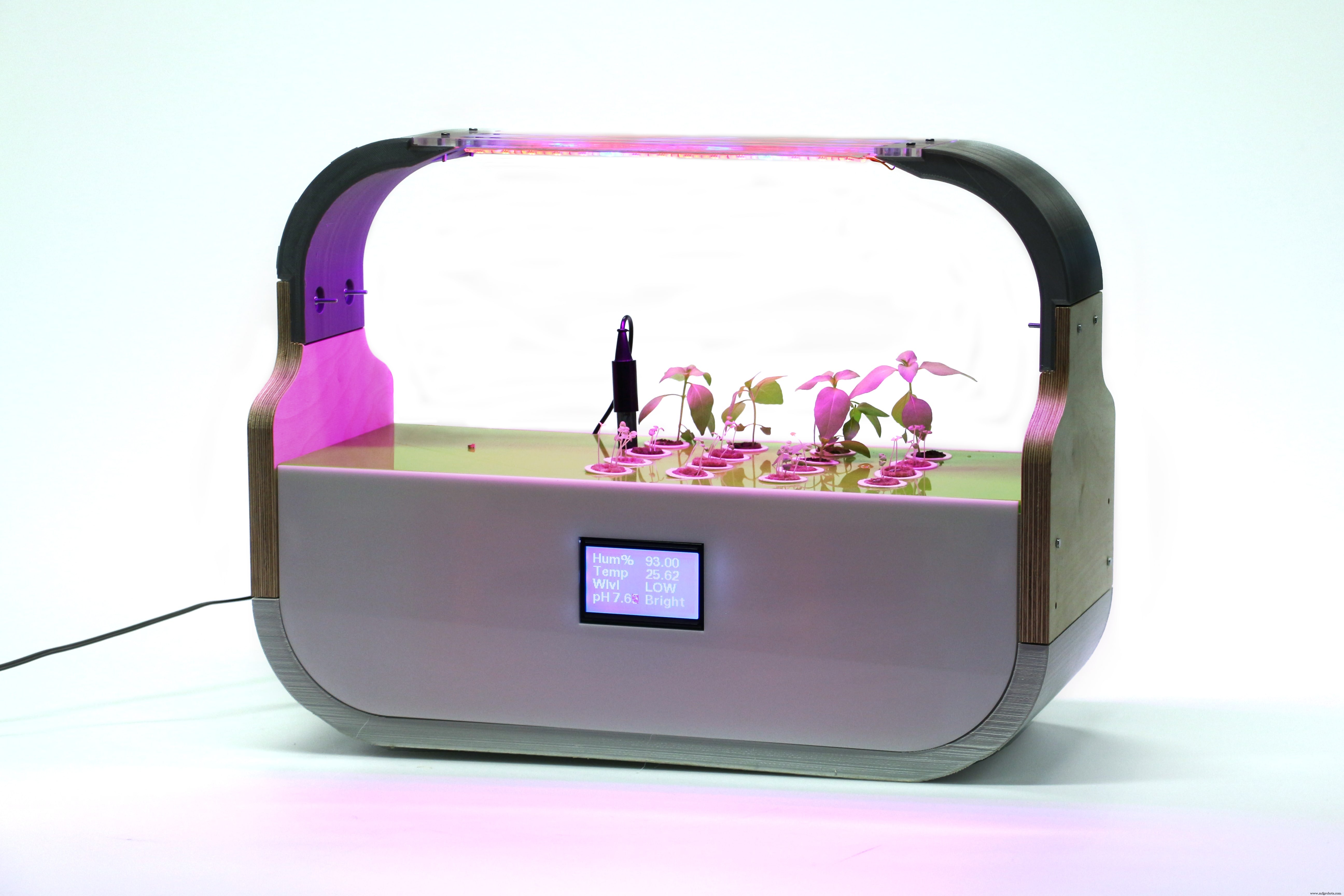
A HERO shot during the working process!
Final Presentation Video
© 2017 Albot Dima. Todos los derechos reservados | Albot.Dumitru@hsrw.org
This work is licensed under a Creative Commons Attribution-NonCommercial-ShareAlike 4.0 International License.

For more details about the project, please visit the official source:
http://archive.fabacademy.org/2017/fablabkamplintfort/students/396/final.html
Código
- GIY Board - CODE
- GIY BOARD - LCD + LIGHT CODE
GIY Board - CODEArduino
#include "dht.h"#include "U8glib.h"#include#include #define DHT11_PIN 2 // what digital pin we're connected to#define ONE_WIRE_BUS 3#define WATER_LEVEL A4#define LDR_PIN A3#define PH_PIN A5#define GROW_LIGHT 10#define FOG_PUMP 13int waterLevel;int LightLevel;int pH;dht DHT;OneWire oneWire(ONE_WIRE_BUS); DallasTemperature waterTemp(&oneWire);U8GLIB_ST7920_128X64 u8g(4, 12, 6, U8G_PIN_NONE);const unsigned char logo [] PROGMEM ={0xFF, 0xFF, 0xFF, 0xFE, 0x7F, 0xFF, 0xFF, 0xFF, 0x00, 0x00, 0x00, 0x00, 0x00, 0x00, 0x00, 0x00,0xFF, 0xFF, 0xFF, 0x00, 0x00, 0xFF, 0xFF, 0xFF, 0x00, 0x00, 0x00, 0x00, 0x00, 0x00, 0x00, 0x00,0xFF, 0xFF, 0xF8, 0x00, 0x00, 0x1F, 0xFF, 0xFF, 0x00, 0x00, 0x00, 0x00, 0x00, 0x00, 0x00, 0x00,0xFF, 0xFF, 0xC0, 0x00, 0x00, 0x03, 0xFF, 0xFF, 0x00, 0x00, 0x00, 0x00, 0x00, 0x00, 0x00, 0x00,0xFF, 0xFF, 0x00, 0x00, 0x00, 0x00, 0xFF, 0xFF, 0x00, 0x00, 0x00, 0x00, 0x00, 0x00, 0x00, 0x00,0xFF, 0xFE, 0x00, 0x03, 0xC0, 0x00, 0x7F, 0xFF, 0x00, 0x00, 0x00, 0x00, 0x00, 0x00, 0x00, 0x00,0xFF, 0xF8, 0x00, 0x07, 0xE0, 0x00, 0x3F, 0xFF, 0x00, 0x00, 0x00, 0x00, 0x00, 0x00, 0x00, 0x00,0xFF, 0xF0, 0x00, 0x1F, 0xF8, 0x00, 0x0F, 0xFF, 0x00, 0x00, 0x00, 0x00, 0x00, 0x00, 0x00, 0x00,0xFF, 0xE0, 0x00, 0x3F, 0xFE, 0x00, 0x07, 0xFF, 0x00, 0x00, 0x00, 0x00, 0x00, 0x00, 0x00, 0x00,0xFF, 0xC0, 0x00, 0x18, 0x1F, 0x00, 0x03, 0xFF, 0x00, 0x00, 0x00, 0x00, 0x00, 0x00, 0x00, 0x00,0xFF, 0x80, 0x00, 0x00, 0x03, 0xC0, 0x01, 0xFF, 0x00, 0x00, 0x00, 0x00, 0x00, 0x00, 0x00, 0x00,0xFF, 0x00, 0x00, 0x00, 0x00, 0xF0, 0x00, 0xFF, 0x00, 0x00, 0x00, 0x00, 0x00, 0x00, 0x00, 0x00,0xFE, 0x00, 0x00, 0x00, 0x00, 0x7C, 0x00, 0x7F, 0x00, 0x00, 0x00, 0x00, 0x00, 0x00, 0x00, 0x00,0xFC, 0x00, 0x00, 0x00, 0x00, 0x3E, 0x00, 0x7F, 0x00, 0x00, 0x00, 0x00, 0x00, 0x00, 0x00, 0x00,0xFC, 0x03, 0x80, 0x00, 0x00, 0x3F, 0x80, 0x3F, 0x00, 0x00, 0x00, 0x00, 0x00, 0x00, 0x00, 0x00,0xF8, 0x07, 0xE0, 0x00, 0x00, 0x1F, 0xE0, 0x1F, 0x00, 0x00, 0x00, 0x00, 0x00, 0x00, 0x00, 0x00,0xFC, 0x1F, 0xF0, 0x00, 0x00, 0x1F, 0xF0, 0x1F, 0x00, 0x00, 0x00, 0x00, 0x00, 0x00, 0x00, 0x00,0xF0, 0x3F, 0xF0, 0x00, 0x00, 0x1F, 0xFC, 0x0F, 0x00, 0x00, 0x00, 0x00, 0x00, 0x00, 0x00, 0x00,0xF0, 0xFF, 0xF0, 0x00, 0x00, 0x1F, 0xFF, 0x0F, 0x00, 0x00, 0x00, 0x00, 0x00, 0x00, 0x00, 0x00,0xE0, 0xFF, 0xF0, 0x00, 0x00, 0x3F, 0xFF, 0x07, 0x00, 0x00, 0x00, 0x00, 0x00, 0x00, 0x00, 0x00,0xE0, 0xFF, 0xF0, 0x00, 0x00, 0x3F, 0xFF, 0x07, 0x00, 0x00, 0x00, 0x00, 0x00, 0x00, 0x00, 0x00,0xC0, 0xFF, 0xF8, 0x00, 0x00, 0x7F, 0xFF, 0x03, 0x00, 0x00, 0x00, 0x00, 0x00, 0x00, 0x00, 0x00,0xC0, 0xFF, 0xFC, 0x00, 0x00, 0xFF, 0xFF, 0x03, 0x00, 0x00, 0x00, 0x00, 0x00, 0x00, 0x00, 0x00,0xC0, 0xFF, 0xFF, 0x00, 0x01, 0xFF, 0xFF, 0x03, 0x00, 0x00, 0x00, 0x00, 0x00, 0x00, 0x00, 0x00,0x80, 0xFF, 0xFF, 0xC0, 0x07, 0xFF, 0xFF, 0x01, 0x00, 0x00, 0x00, 0x00, 0x00, 0x00, 0x00, 0x00,0x80, 0xFF, 0xFF, 0xFF, 0xFF, 0xFF, 0xFF, 0x01, 0x00, 0x00, 0x00, 0x00, 0x00, 0x00, 0x00, 0x00,0x80, 0xFF, 0xFF, 0xFF, 0xFF, 0xFF, 0xFF, 0x01, 0x00, 0x00, 0x00, 0x00, 0x00, 0x00, 0x00, 0x00,0x80, 0xFF, 0xFF, 0xFF, 0xFF, 0xFF, 0xFF, 0x01, 0x00, 0x00, 0x00, 0x00, 0x00, 0x00, 0x00, 0x00,0x80, 0xFE, 0x1F, 0xFF, 0xFF, 0xF0, 0x3C, 0x01, 0x00, 0x00, 0x00, 0x00, 0x00, 0x00, 0x00, 0x00,0x80, 0xF8, 0x03, 0xFF, 0xFF, 0xC0, 0x10, 0x01, 0x00, 0x00, 0x00, 0x00, 0x00, 0x00, 0x00, 0x00,0x80, 0xF0, 0x01, 0xFF, 0xFF, 0x80, 0x00, 0x01, 0x00, 0x00, 0x00, 0x00, 0x00, 0x00, 0x00, 0x00,0x00, 0xF0, 0x00, 0xFF, 0xFF, 0x00, 0x00, 0x01, 0x00, 0x00, 0x00, 0x00, 0x00, 0x00, 0x00, 0x00,0x00, 0xE0, 0x00, 0x7F, 0xFE, 0x00, 0x00, 0x01, 0x00, 0x00, 0x00, 0x00, 0x00, 0x00, 0x00, 0x00,0x80, 0xE0, 0x00, 0x3F, 0xFC, 0x00, 0x00, 0x01, 0x00, 0x00, 0x00, 0x00, 0x00, 0x00, 0x00, 0x00,0x80, 0xE0, 0x00, 0x1F, 0xFC, 0x00, 0x00, 0x01, 0x00, 0x00, 0x00, 0x00, 0x00, 0x00, 0x00, 0x00,0x80, 0xE0, 0x00, 0x1F, 0xF8, 0x00, 0x00, 0x01, 0x00, 0x00, 0x00, 0x00, 0x00, 0x00, 0x00, 0x00,0x80, 0xE0, 0x00, 0x0F, 0xF8, 0x00, 0x00, 0x01, 0x00, 0x00, 0x00, 0x00, 0x00, 0x00, 0x00, 0x00,0x80, 0xE0, 0x00, 0x0F, 0xF0, 0x00, 0x00, 0x01, 0x00, 0x00, 0x00, 0x00, 0x00, 0x00, 0x00, 0x00,0x80, 0xE0, 0x00, 0x0F, 0xF0, 0x00, 0x01, 0x01, 0x00, 0x00, 0x00, 0x00, 0x00, 0x00, 0x00, 0x00,0x80, 0xE0, 0x00, 0x07, 0xF0, 0x00, 0x07, 0x01, 0x00, 0x00, 0x00, 0x00, 0x00, 0x00, 0x00, 0x00,0xC0, 0xF0, 0x00, 0x07, 0xF0, 0x00, 0x07, 0x03, 0x00, 0x00, 0x00, 0x00, 0x00, 0x00, 0x00, 0x00,0xC0, 0xF0, 0x00, 0x07, 0xF0, 0x00, 0x0F, 0x03, 0x00, 0x00, 0x00, 0x00, 0x00, 0x00, 0x00, 0x00,0xC0, 0xF8, 0x00, 0x07, 0xF0, 0x00, 0x0F, 0x03, 0x00, 0x00, 0x00, 0x00, 0x00, 0x00, 0x00, 0x00,0xC0, 0xF8, 0x00, 0x07, 0xF0, 0x00, 0x1F, 0x07, 0x00, 0x00, 0x00, 0x00, 0x00, 0x00, 0x00, 0x00,0xE0, 0xFC, 0x00, 0x07, 0xF0, 0x00, 0x1F, 0x07, 0x00, 0x00, 0x00, 0x00, 0x00, 0x00, 0x00, 0x00,0xE0, 0xFE, 0x00, 0x0F, 0xF0, 0x00, 0x3F, 0x07, 0x00, 0x00, 0x00, 0x00, 0x00, 0x00, 0x00, 0x00,0xF0, 0x3E, 0x00, 0x0F, 0xF0, 0x00, 0x7C, 0x0F, 0x00, 0x00, 0x00, 0x00, 0x00, 0x00, 0x00, 0x00,0xF0, 0x1E, 0x00, 0x1F, 0xF8, 0x00, 0xF8, 0x0F, 0x00, 0x00, 0x00, 0x00, 0x00, 0x00, 0x00, 0x00,0xF8, 0x06, 0x00, 0x1F, 0xFC, 0x01, 0xE0, 0x1F, 0x00, 0x00, 0x00, 0x00, 0x00, 0x00, 0x00, 0x00,0xFC, 0x00, 0x00, 0x7F, 0xFF, 0x0F, 0x80, 0x3F, 0x00, 0x00, 0x00, 0x00, 0x00, 0x00, 0x00, 0x00,0xFC, 0x00, 0x00, 0x7F, 0xFF, 0xFF, 0x00, 0x3F, 0x00, 0x00, 0x00, 0x00, 0x00, 0x00, 0x00, 0x00,0xFE, 0x00, 0x00, 0x7F, 0xFF, 0xFC, 0x00, 0x7F, 0x00, 0x00, 0x00, 0x00, 0x00, 0x00, 0x00, 0x00,0xFF, 0x00, 0x00, 0x7F, 0xFF, 0xF0, 0x00, 0xFF, 0x00, 0x00, 0x00, 0x00, 0x00, 0x00, 0x00, 0x00,0xFF, 0x80, 0x00, 0x7F, 0xFF, 0xC0, 0x01, 0xFF, 0x00, 0x00, 0x00, 0x00, 0x00, 0x00, 0x00, 0x00,0xFF, 0xC0, 0x00, 0x7F, 0xFF, 0x80, 0x03, 0xFF, 0x00, 0x00, 0x00, 0x00, 0x00, 0x00, 0x00, 0x00,0xFF, 0xE0, 0x00, 0x7F, 0xFE, 0x00, 0x07, 0xFF, 0x00, 0x00, 0x00, 0x00, 0x00, 0x00, 0x00, 0x00,0xFF, 0xF0, 0x00, 0x1F, 0xF8, 0x00, 0x0F, 0xFF, 0x00, 0x00, 0x00, 0x00, 0x00, 0x00, 0x00, 0x00,0xFF, 0xF8, 0x00, 0x0F, 0xF0, 0x00, 0x1F, 0xFF, 0x00, 0x00, 0x00, 0x00, 0x00, 0x00, 0x00, 0x00,0xFF, 0xFC, 0x00, 0x03, 0xC0, 0x00, 0x3F, 0xFF, 0x00, 0x00, 0x00, 0x00, 0x00, 0x00, 0x00, 0x00,0xFF, 0xFF, 0x00, 0x00, 0x00, 0x00, 0xFF, 0xFF, 0x00, 0x00, 0x00, 0x00, 0x00, 0x00, 0x00, 0x00,0xFF, 0xFF, 0xC0, 0x00, 0x00, 0x03, 0xFF, 0xFF, 0x00, 0x00, 0x00, 0x00, 0x00, 0x00, 0x00, 0x00,0xFF, 0xFF, 0xF0, 0x00, 0x00, 0x1F, 0xFF, 0xFF, 0x00, 0x00, 0x00, 0x00, 0x00, 0x00, 0x00, 0x00,0xFF, 0xFF, 0xFE, 0x00, 0x00, 0x7F, 0xFF, 0xFF, 0x00, 0x00, 0x00, 0x00, 0x00, 0x00, 0x00, 0x00,0xFF, 0xFF, 0xFF, 0xFD, 0x3F, 0xFF, 0xFF, 0xFF, 0x00, 0x00, 0x00, 0x00, 0x00, 0x00, 0x00, 0x00};bool first;float hum =0.0;double T=0.0;void dht_test(float * humPerc);void setup(void) { waterTemp.begin(); pinMode (GROW_LIGHT, OUTPUT); pinMode (FOG_PUMP, OUTPUT); digitalWrite (GROW_LIGHT, HIGH); first =true; // assign default color value if ( u8g.getMode() ==U8G_MODE_R3G3B2 ) { u8g.setColorIndex(255); // white } else if ( u8g.getMode() ==U8G_MODE_GRAY2BIT ) { u8g.setColorIndex(3); // max intensity } else if ( u8g.getMode() ==U8G_MODE_BW ) { u8g.setColorIndex(1); // pixel on } else if ( u8g.getMode() ==U8G_MODE_HICOLOR ) { u8g.setHiColorByRGB(255,255,255); } // picture loop u8g.firstPage(); do { u8g.drawBitmapP( 32, 0, 16, 64, logo); } while( u8g.nextPage() ); dht_test(&hum);}void RefreshDisplay(float * humPerc, double *T, int *WL, int *LL, int *pH_value) { u8g.setFont(u8g_font_fub11); u8g.setFontRefHeightExtendedText(); u8g.setDefaultForegroundColor(); u8g.setFontPosTop(); u8g.drawStr( 4, 0, "Hum%"); u8g.setPrintPos( 68, 0); u8g.print( *humPerc); u8g.drawStr( 4, 15, "Temp"); u8g.setPrintPos( 68, 15); u8g.print( *T); u8g.drawStr( 4, 30, "Wlvl"); if (*WL ==0){ u8g.drawStr (68, 30,"EMPTY!"); digitalWrite (FOG_PUMP, LOW); } else{ if (*WL <800) u8g.drawStr (68, 30,"LOW"); else { digitalWrite(FOG_PUMP, HIGH); u8g.drawStr (68, 30,"HIGH"); } } if (*LL <100) { u8g.drawStr (68, 45,"Dark"); } else if (*LL <200) { u8g.drawStr (68, 45,"Dim"); } else if (*LL <500) { u8g.drawStr (68, 45,"Light"); } else if (*LL <800) { u8g.drawStr (68, 45,"Bright"); } else { u8g.drawStr (68, 45,"2Bright"); } double voltage =5.0 / 1024.0 * (*pH_value); float Po =7 + ((2.5 - voltage) / 0.18); u8g.drawStr (4, 45,"pH"); u8g.setPrintPos( 28, 45); u8g.print( Po); }void loop(void) {waterTemp.requestTemperatures();T =waterTemp.getTempCByIndex(0);waterLevel =analogRead(WATER_LEVEL);LightLevel =analogRead(LDR_PIN);pH =analogRead (PH_PIN);char status;int chk =DHT.read11(DHT11_PIN);hum =DHT.humidity; dht_test(&hum); if(first) { first =false; } else { u8g.firstPage(); do { RefreshDisplay(&hum, &T,&waterLevel, &LightLevel, &pH); } while( u8g.nextPage() ); }}void dht_test(float * humPerc) { // Wait a few seconds between measurements. delay(1000);}
GIY BOARD - LCD + LIGHT CODEArduino
#include "U8glib.h"int led =10;U8GLIB_ST7920_128X64 u8g(4, 12, 6, U8G_PIN_NONE);void draw(void) { // graphic commands to redraw the complete screen should be placed here u8g.setFont(u8g_font_unifont); u8g.setPrintPos(0, 20); // call procedure from base class, http://arduino.cc/en/Serial/Print u8g.print("GIY Project v1.0!");}void setup(void) { pinMode (led, OUTPUT); digitalWrite (led, HIGH);}void loop(void) { // picture loop u8g.firstPage(); do { draw(); } while( u8g.nextPage() ); // rebuild the picture after some delay delay(500);} Esquemas
Proceso de manufactura
- Tarjeta de visita del juego Tic Tac Toe
- Sensor de temperatura múltiple
- Control de cautín de bricolaje para 862D +
- MotionSense
- Seguridad contra incendios de la impresora 3D
- Medidor de IoT con Arduino, Yaler e IFTTT
- Levitación electromagnética repulsiva Arduino
- Bot de agarre de control remoto
- Registrador de datos de globos meteorológicos con tecnología Arduino
- ArduFarmBot - Parte 2:Estación remota e implementación de IoT
- CoroFence - Detector térmico🖖